
Abstract
Indoor magnetic field has attracted considerable attention in indoor location–based services, because of its pervasive and stable attributes. Generally, in order to harness the location features of the magnetic field, particle filters are introduced to simulate the possibilities of user locations. Real-time magnetic field fingerprints are matched with model fingerprints to adjust the location possibilities. However, the computation overheads of the magnetic matching are rather high, thus limiting their applications to mobile computing platforms and indoor location–based service providers that serve massive users. In order to reduce the computation overhead, the article presents a low-cost magnetic field fingerprint matching scheme. Based on the low-frequency features of the magnetic field, the scheme updates particle weights according to the mass center of the magnetic field deltas of pedestrian steps. The proposed low-cost scheme decreases the complexity of real-time fingerprints without harming the positioning performance. In order to further improve the positioning accuracy, not asking users to hold the smartphone in fixed attitudes, we also present a smartphone attitude detection method that enables the proposed scheme to automatically select proper fingerprints. Experiments convincingly reveal that the proposed scheme achieves about 1 m accuracy at 80% with low computation overheads.
Keywords
Introduction
Indoor location-base services (ILBS) on smartphones are changing our lives. For example, international travelers using smartphone applications are able to visit new countries without worrying getting lost, to obtain recommendation about shops and events, and to query real-time information about buses, taxis, and trains. Considering outdoor scenarios, all these conveniences come from the support of global navigation satellite systems (GNSS). However, the signals from satellites are attenuated by the walls and roofs of buildings; therefore, they are unable to provide ILBS.
In order to implement indoor localization services, researchers have studied various indoor positioning techniques using different technologies, including Wi-Fi, 1 Bluetooth Low Energy (BLE), 2 acoustic signals,3–5 Channel State Information (CSI),6,7 Ultra-Wideband (UWB), 8 Cell, 9 Camera,10,11 Inertial Navigation Systems (INS), 12 and visible light.13,14 Systems based on Wi-Fi and BLE signals do not achieve high accuracies due to the fluctuation of these signals.15–21 The performances of acoustic-based4,5 and CSI methods are quite well; however, the two methods need dense sampling, thus making it difficult to be deployed in large environments. The UWB needs to deploy extra infrastructures. The positioning accuracy of cell-based systems is rather low. The camera method is power hungry because it needs to take lots of photos of nearby environments. The drift problem of the inertial sensors causes a positioning result that becomes divergent quickly. The emerging light-emitting diode (LED) provides an identification-based positioning method, but it only works under special LED bulbs. 22
Generally, the low-cost limitation of public ILBS requires infrastructure-free and high-resolution positioning signals. Considering indoor scenarios, signals obtained from the geomagnetic field are distorted by large iron structures and present a pervasive and a stable characterization. Comparing with Wi-Fi signals, the dimension of the magnetic field–based signals is rather low (only three dimensions). Consequently, researchers leverage magnetic field fingerprints (a sequence of magnetic field vectors) to represent the feature of a location, rather than a single vector. Specifically, magnetic field systems compare real-time fingerprints (e.g. gathered by mobile devices) with a labeled fingerprint database, and then evaluate the most similar location as the positioning result. Although extending the fingerprint length improves its ability to characterize the environment, the exponentially increasing of the comparison possibilities of potential fingerprints require an accurate trade-off decision in order to use this information for real-time positioning purposes. Therefore, researchers leverage a Monte Carlo method (i.e. particle filtering) to limit the number of potential fingerprints to the number of particles.23–27 These technologies leverage the pedestrian dead reckoning (PDR) to move particles, then update particle weights by comparing magnetic field fingerprints. The fingerprints are warped due to different user step lengths; therefore, researchers utilize dynamic time warping (DTW) algorithm to measure the similarity of the warped fingerprints.24,25,28
However, DTW-based methods are computationally intractable, especially when particle populations are large. Considering limited smartphone battery capacities, it is difficult to apply the DTW-based solution on mobile platforms. The high computation overhead also troubles the ILBS providers who are interested to serve massive users 29 (e.g. saving hardware cost). In Shao et al., 30 we had partially described the low-frequency features of the indoor magnetic field and, based on the feature, presented a low-cost matching scheme for magnetic field strength fingerprints. In order to further improve our positioning performance, this work updates the matching scheme by extending magnetic field fingerprints in spherical coordinates. Specifically, the magnetic field strength is the modulus of the magnetic field vector under the Cartesian coordinate. In spherical coordinates, the strength of the signal is only one of the dimensions of the three-dimensional (3D) magnetic field vector, as Figure 1 reveals. The other two dimensions (polar and azimuth angle) can be used to provide more location information. In this work, we extend our previous study about the mass-centered matching scheme in order to enable it to fit with multidimensional fingerprints.

Magnetic field vector in spherical coordinates.
The challenge of utilizing the extended fingerprints is that the azimuth and polar angle dimensions of the magnetic field vector are susceptible to smartphone attitudes. The indoor magnetic field is stable with respect to earth frames, but their measurements are in the smartphone frame. Thus, the measurement of a place varies when the smartphone attitude changes, leading the fingerprint matching of the magnetic field to fail. In order to avoid a wrong matching, traditional methods discard the azimuth and polar angle dimensions and only keep the attitude-free magnitude dimension. However, in most of the application scenarios, users hold smartphones in different but common attitudes. Therefore, we can utilize the azimuth and polar angle dimensions of these attitudes to improve the positioning accuracy. This work starts from the assumption that users who are interested in ILBS use their own devices in upward forward and horizontal (UFH) attitude, that is, the smartphone is held with the screen horizontal and pointing upward and the long edge pointing forward, as Figure 2 shows. Based on the inertial features of the UFH attitude, we propose a Bayesian model to predict the real-time attitude of the smartphone. The proposed attitude detection method enables the mass-centered fingerprint matching scheme to update particle weights with proper magnetic field dimensions under various smartphone attitudes.

The most common attitude for a user to read location fixes from a smartphone.
As a conclusion, with respect to our previous work on this topic, 30 the contributions of the article are in threefold:
We redesign a positioning system based on the mass-centered features of the magnetic field to decrease the computational cost of the fingerprint matching. Our work investigates the spatial frequency attributes of indoor magnetic fields and finds that the Nyquist frequency of indoor magnetic fields is lower than step frequencies in the spatial domain. Based on the Nyquist criterion, we present the mass-centered fingerprint matching scheme to decrease the computational overhead. In order to improve positioning accuracies, we also extend our scheme to enable it fitting multidimensional fingerprints. Besides, we improve the particle step-length and moving direction estimation methods to fine-tune the positioning performance. Experiments reveal that the proposed scheme significantly decreases computational overheads and still achieves good accuracy.
We extensively describe an attitude detection method that is able to identify the UFH attitude from other attitudes. Our work analyzes the smartphone attitudes of different users and investigates the inertial attributes of the smartphones when users reading location fixes. Based on the frequency pattern of these attributes under different attitudes, we present a Bayesian model to predict real-time smartphone attitudes from accelerometer signals. The attitude detection method enables the mass-centered fingerprint matching scheme to automatically select proper magnetic field dimensions in different walking patterns.
According to Potorti et al., 31 we test our system in real test sites, extending our preliminary previous results. 30 Experiments convincingly reveal that the proposed positioning method reaches a remarkable performance considering various smartphones, different target users, and different scenarios. Finally, we show a comparison between our results and state-of-the-art systems.
The rest of the article is organized as follows. The “Related work” section introduces related works. The “System overview” section provides an overview of the proposed positioning system. The “UFH attitude detection algorithm” section analyzes the features of upward and forward attitude and proposes a Bayesian-based attitude detection model. The “Mass-centered magnetic weight update scheme” section explains the proposed low-cost high-precision weight update scheme for magnetic matching. The “Augmented particle motion model” section describes the augmented step-length and moving direction estimation methods. The “Experimental campaign” section extensively evaluates the proposed attitude detector and the magnetic weight update scheme under various factors. Finally, the “Conclusion” section concludes the article.
Related work
Fingerprinting techniques are widely used in ILBS. Wi-Fi-based positioning is one of the most important fingerprinting techniques used in this context because of the pervasive deployment of Wi-Fi Access Points for Internet accessing purpose.
The Wi-Fi-based algorithms can be divided into deterministic and probabilistic methods. The deterministic methods are easier to be implemented because they only leverage various similarity metrics to differentiate online and off-line fingerprints, then calculate positioning results as the closest fingerprint locations in signal space. The usually used similarity metrics include Euclidean distance, 32 Tanimoto similarity, 33 and cosine similarity. 34
The magnetic field is another promising technique for pedestrian localization in indoor environments because of its outstanding features: existing pervasively all around the world, low battery power required when positioning fingerprints are collected, stable in time, and remarkable spatial discernibility. Magnetic field schemes can achieve a much higher accuracy (around 1–5 m) than Wi-Fi-based schemes (about 5–10 m). 35 Researchers have studied several approaches to harness the indoor magnetic field for positioning purpose. Wang et al. 36 leverage unsupervised learning to find location-related magnetic anomalies. Then these anomalies are used as landmarks to pinpoint specific indoor locations. The landmark method is easy and simple, but it only exploits the magnetic fields of few landmark points; therefore, the magnetic field is not fully utilized. Magicol 25 models temporal magnetic measurements as sequences of strings, then solves target positions with traditional string matching and dynamic programming methods. However, these dynamic programming–based matching schemes are computationally expensive. Shu et al. 37 propose a leader–follower mode-based scheme. Such a mode is particularly useful when floor plans are missing, but this mode is tailored to some specific applications. Magnetic field–based schemes are found to achieve reasonably high localization accuracy, but it is difficult for them to provide large-scale site deployments due to the decreasing discernibility of magnetic fingerprints. 38 Therefore, additional sensing information is needed to make the fingerprints more discernible. 39 For example, we can use well-known Wi-Fi-based techniques to provide initial positioning areas, then leverage the magnetic positioning to further improve the positioning accuracy.
Smartphone-based attitude detection is widely used in the falling-down detection of global public health in an aging society. Shen et al. 40 use fuzzy Petri net to analysis and develop the identification of human actions, including normal action, exercising, and falling down. La Concepcion et al. 41 leverage data retrieved from accelerometer sensors to generate discrete variables, then the core of the algorithm Ameva is used to develop the selection, discretization, and classification technique for activity recognition. Hakim et al. 42 propose a threshold-based fall detection algorithm using a supervised machine learning algorithm to classify activities of daily living (ADL). However, all these attitude detection methods focus on the health and safety implication of individuals rather than improving the accuracy of a positioning system. The attitude detection scheme proposed in this article aims at finding the proper attitude for fully utilizing the features of magnetic fields.
As a summary, compared with the traditional magnetic field positioning methods, the proposed scheme leverages a mass-centered scheme to decrease the computational overhead maintaining high positioning accuracies. Furthermore, we make full use of magnetic field features by automatically extending magnetic field fingerprints under the UFH attitude with the help of the proposed attitude detection method.
System overview
This section provides an outline of the proposed positioning system. The system combines PDR and magnetic field fingerprint matching with a strengthened particle filtering. Particle filtering is also known as Monte Carlo methodology. 43 The basic idea is to use discrete random measurements to approximate the probability of distributions, which is suitable for high-dimensional indoor location estimations. Particle filtering consists of four steps: particle initialization, movements, weight updates, and resampling.
As Figure 3 shows, the proposed system consists of five modules: magnetic model, magnetic fingerprint, step detector, attitude detector, and the mass-centered magnetic positioning module. The magnetic model stores off-line training magnetic field features. The magnetic fingerprint module collects real-time fingerprints. The step detector 44 drives particles move forward. The attitude detector detects the smartphone’s real-time attitudes. The mass-centered magnetic positioning module runs the core positioning algorithm to evaluate user’s location.

The architecture of the proposed positioning system.
The overall process of the proposed positioning method is shown in Algorithm 1. In the particle initialization step, particles are spread around an initial position

UFH attitude detection algorithm
The article discusses various smartphone attitudes. These attitudes can be defined by the screen facing and smartphone long edge pointing directions, as well as screen inclination status. The abbreviations of smartphone attitudes used in this article are listed in Table 1 for clearance.
Attitude abbreviations.

UF: upward forward; UL: upward leftward; UR: upward rightward; UB: upward backward; UFH: upward forward horizontal; UFNH: upward forward non horizontal; UNF: upward non forward; ULRB: upward and leftward or rightward or backward; NUF: non upward forward.
UFH attitude is the most common smartphone holding manner when users focus their eyes on smartphone screens to read location fixes. In order to detect this attitude and improve its positioning accuracy, the proposed scheme divides UFH attitude detection into three steps: upward attitude detection, upward forward (UF) attitude detection, and UFH attitude detection.
Upward attitude detection
For ILBS users, UFH attitude is the most common way to read location fixes. This attitude brings in two benefits for particle filter–based magnetic positioning. First, the moving direction is the same as the measured direction, which is helpful in moving particles. Second, the smartphone attitude in the training phase and positioning phase are the same; therefore, the 3D vector information can be used to improve positioning accuracy.
Except for UFH attitude, there are many manners for pedestrian indoor positioning, including hand-swing, calling, pocket, upward and leftward (UL) attitude, upward and rightward (UR) attitude, and upward and backward (UB) attitude. In order to distinguish the UFH attitude from other many possible attitudes, the article divides the detection process into three steps: upward attitude detection, UF attitude detection, and UFH attitude detection.
Judging upward attitude first can effectively reduce the searching space of UF attitude detection, because it removes all screen downward and sideward modes, including hand-swing, calling, and pocket. As Figure 4 reveals, when a screen facing upward, the gravity mainly acts on the z-axis of the accelerometer. Therefore, the article judges that a smartphone is in an upward attitude when the acceleration on z-axis is comparable to gravity.

Gravity pressure on a smartphone.
UF attitude detection
When a smartphone is in an upward attitude, the possible holding manners can be classified into four classes, as Figure 5 shows. UF is the most common way that users hold smartphones because smartphones are designed to have a rectangle shape. The short edge is easy for users to hold; the long edge enlarges the visible area. Besides, the position of front cameras, control buttons, and default layouts of applications all suppose users to hold smartphones in UF attitude. Nevertheless, there are chances that users may hold phones in UB attitude by mistake, or phones are in gaming modes like UL and UR attitudes. Except the UF, UB, UL and UR attitudes, there are also many other smartphone holding manners. However, these manners are seldom used because the contents on screens do not align with the eyes. Therefore, the article only studies the method that separate the UF attitude from UB, UR, and UL attitudes.
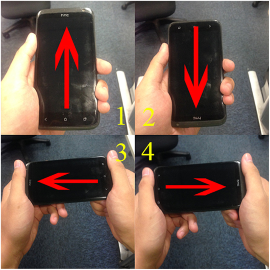
Four common holding manners when a smartphone is held upward. 1, UF attitude; 2, UB attitude; 3, UL attitude; and 4, UR attitude.
As Figure 6 shows, acceleration signals vary when a user walks; therefore, the article analyzes the acceleration patterns of the UF attitude. Based on our study, we define three feature events of UF attitude when users walk. The first feature event is
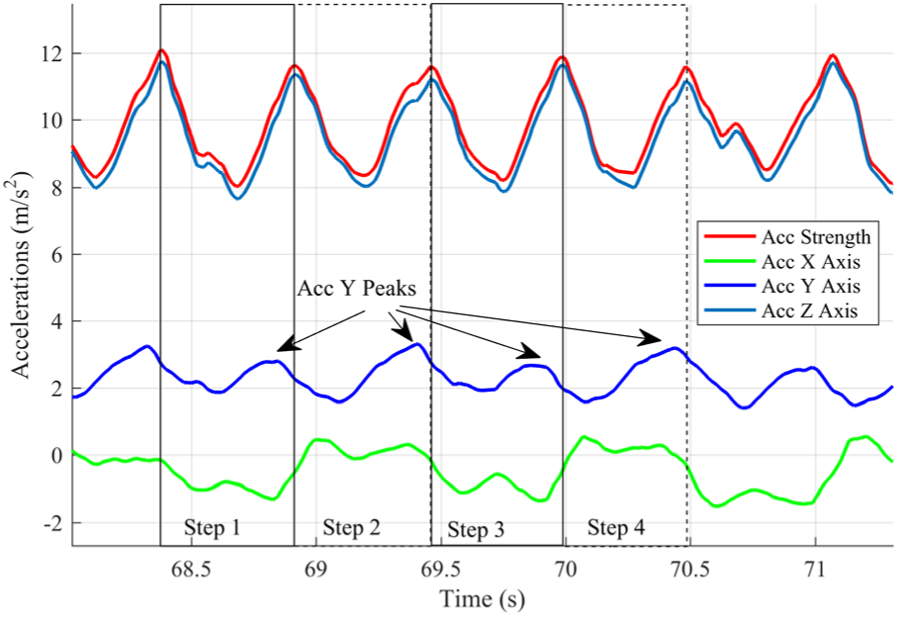
Step acceleration features of the UF attitude. Acc means acceleration. The figure shows a 3-s walking. The four rectangles indicate the time scope of four steps. The negative values indicate opposite directions.
The second feature event is
The third feature event is
Although the three feature events occur in the UF attitude, they may appear in UR, UL, and UB attitudes as well. In order to study the probability of different feature events, we employed 100 users and asked them to walk 100 steps with a smartphone in the four attitudes, respectively. Table 2 illustrates the probabilities of feature event combinations under different attitudes, indicating that any feature events may appear in multiple attitudes. It is worth to notice that the three feature events are not mutually exclusive, so the probability sum of every column is not equal to one.
The conditional probabilities of feature event under different attitude conditions.

UF: upward forward; UL: upward leftward; UR: upward rightward; UB: upward backward.
Therefore, the article proposes a Bayesian-based method to estimate the probability of UF attitudes when different combinations of acceleration feature events occur. There are eight feature event combinations:

The conditional probabilities of different feature event combinations under different attitude conditions.

UF: upward forward; UL: upward leftward; UR: upward rightward; UB: upward backward.
The result is shown in Table 4. Based on this table, we can infer that a smartphone is in UF attitude when feature event combination
The conditional probabilities of UF attitude under different feature event combinations.

UF: upward forward.
UFH attitude detection
The UFH attitude detection estimates when the UF attitude approximates the horizontal plane, that is, whether the angle

where the

Horizontal incline angle calculation under the UF attitude.
As a summary, the UFH attitude detection scheme is shown as pseudo-code in Algorithm 2.

Mass-centered magnetic weight update scheme
When applying magnetic field fingerprint matching to particles, we find that the mass-centered feature of magnetic fields can be utilized to decrease the computation overhead of the positioning system. Then, we propose the mass-centered weight update scheme. Finally, the time complexity of the algorithm is analyzed.
The mass-centered feature of magnetic fields
The proposed positioning algorithm is based on a particle filter. Therefore, when a user takes a step, particles will move to new positions, as shown in Algorithm 1. As Figure 8 reveals, the article defines the error metric between a ground-truth position and a particle position as a particle positioning error (PE). Similarly, magnetic strength error (MSE) is defined as the error metric between a measured magnetic strength delta
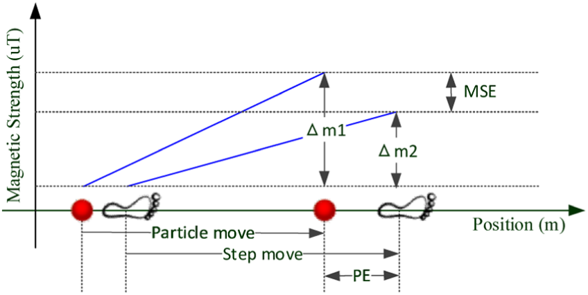
Illustration of a particle positioning error (PE) and a magnetic strength error (MSE). The footprints stand for the start and end positions of a step. The red dots stand for the start and end positions of a particle movement.
Indoor magnetic fields are low-frequency signals in the space domain. Considering the average step frequency of pedestrians is 1.53 samples/m, 46 based on Nyquist frequency theory, 47 the lossless frequency of steps is 0.765 samples/m. Based on our experiments, the lossless frequency of steps covers more than 98% of indoor magnetic field energy, as Figure 9 reveals. Therefore, we propose to represent the magnetic strength measurements during a step phase with the MSE.

Energy spectral analysis of the indoor magnetic field in the space domain. The result is based on magnetic fingerprints of several floors.
Considering several steps, the article defines the mean of PEs as MPE and the mean of absolute MSEs as MMSE. Given N particles and a sliding step window with W steps, for each particle i, its MPE and MMSE at step t are described as


In equation (3),
The relationship between MPE and MMSE can be represented as a comet, shown in Figure 10 with the help of kernel density analysis. The relationship comet consists of three parts: nucleus, coma, and tail. The nucleus is the highest density area containing most of the particles. Because the particle movement model follows a normal distribution, the nucleus gathers most particles around the mean step length. Therefore, the high-density nucleus decides localization results. The diverging tail consisted of large MPE particles, because randomly generated step lengths of them are far away from the true step length, either too big or too small. Particles in the coma are “valuable” particles, because their MPEs are small, in other words closing to the ground truth. It is worth noticing that these small MPE particles have small MMSE as well.
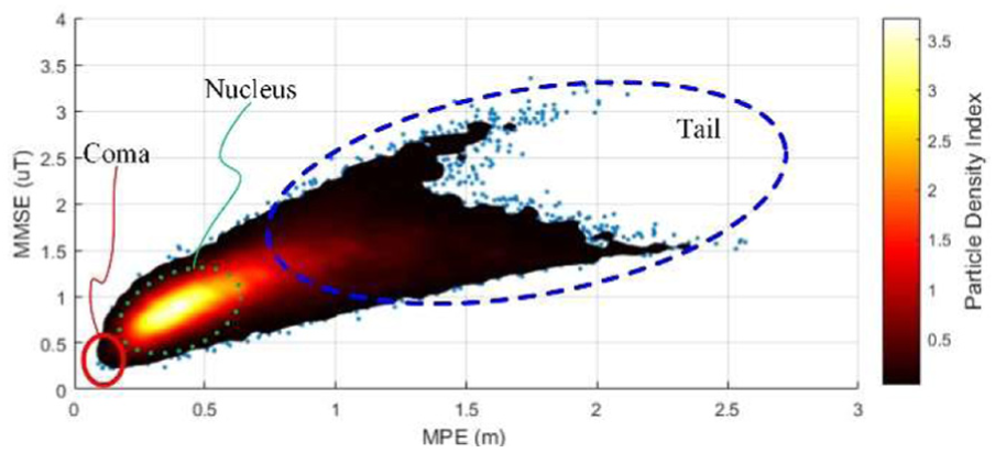
Kernel density estimation of particles. The brighter area stands for higher particle density. The relation comet is drawn with nine steps sliding window.
Intuitively, as shown in Figure 10, positioning accuracies can be improved by increasing the weights of coma particles to tune the nucleus toward the coma.
The mass-centered weight update scheme
Based on this mass-centered feature, the article presents the weight update scheme of particles. In order to improve positioning accuracy, the article needs to increase the weight of particles with small MPEs. However, in positioning phases, only MMSE is available. Based on the relationship between MMSE and MPE, the scheme selects small MPE particles via small MMSE indexes and then increases their weights
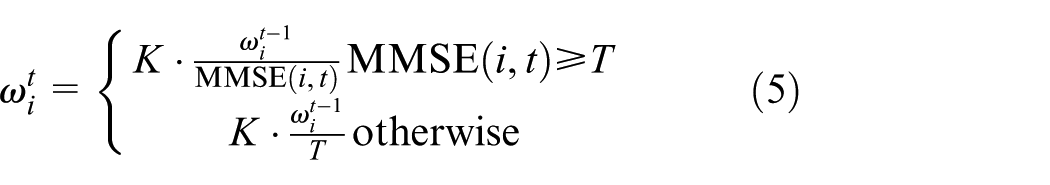
As shown in equation (5), given N particles, the weight
With the help of the proposed UFH attitude detecting algorithm, the mass-centered weight update scheme can be applied to the three dimensions of magnetic vectors
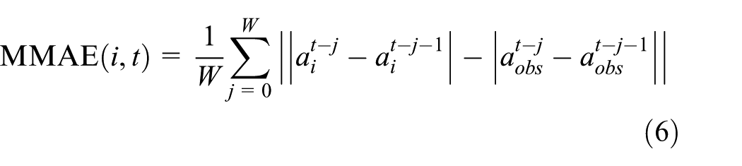
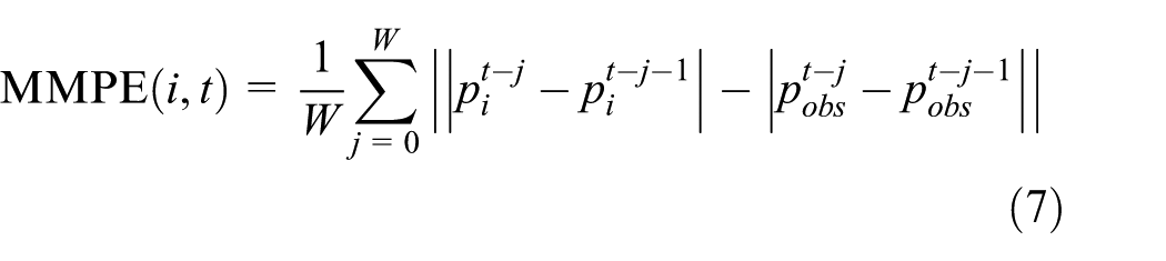

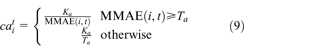


Equations (6) and (7) calculate the mean magnetic azimuth error (MMAE) and the mean magnetic polar angle error (MMPE) of particle i at step t, with a and p stand for azimuth and polar angle. Equations (8) and (10) compute the weights update coefficients
Time complexity analysis
Assuming the number of particles is N, then the time complexity of attitude detection is
Augmented particle motion model
In order to further improve the positioning performance of the particle filtering, we also improve the step-length and moving direction estimation methods to include the complexity of the indoor environments.
Personal dynamic step-length estimation
Although smartphones are equipped with accelerometers, they are error-prone to calculate user moving distances by directly double-integrating acceleration data because of the sensor drift problems. 48 Therefore, researchers utilize step event–based models to estimate user step lengths, and then the estimation of the user moving distance is the sum of continuous step lengths. Researchers have found that the relationship between step frequencies and lengths is linear when users naturally walk.49,50 However, step lengths are affected by many dynamic factors: changing walking speed, walking on slippery roads, and using different shoes. These factors require step-length estimation methods to be able to update themselves automatically.
In order to adapt these changing factors, the article proposes a self-adaptive step-length model based on genetic algorithm (GA) 51 and particle filtering. Inspired by the process of natural selection, the proposed method leverages a population of candidate model parameters to evolve toward personalized models. Particle filtering has a large group of populations; therefore, the proposed method combines the step-length population with particle filtering. Candidate step-length parameters are stored into particles, then the estimation evolves with particle filtering. The proposed dynamic step-length estimation model is
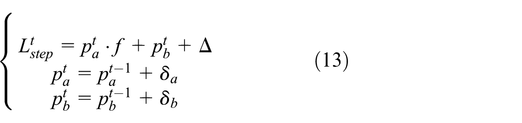
where
The evolution starts from a population of randomly generated individuals distributed around generic
Another challenge is that when a user turning a corner, the body moving distance is shorter than the actual step length. As Figure 11 shows, when a user is turning left, his right foot moves first. The left and right step lengths are equal, so the possible positions of one foot lie on a circle with the other foot as the pivot. If the user is walking straight, the body direction difference

where

A turning step length. When one foot is as a pivot, the other foot lies on a circle.
The direction compensation of particle movements
In indoor environments, azimuth angles measured by smartphone compasses usually deviate from the ground truth, because ferromagnetic structures distort indoor magnetic fields, consequently affecting the azimuth measurements. As Figure 12 shows, measured azimuths deviate from the true orientations in areas A and C. Therefore, if particles move along the distorted azimuth measurements, they will deviate from corridors, thus causing poor positioning accuracy.
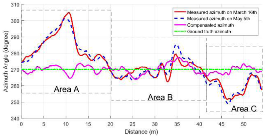
The azimuth deviations evaluated along a corridor. In area B, azimuth measurements are around the ground-truth azimuth. In areas A and C, the measurements deviate from the ground truth.
Indoor magnetic fields are steadily warped by the steel structures of buildings.16,26 Therefore, indoor magnetic fields are static, as Figure 12 shows, and the azimuth deviations at the same positions are similar in different months. If we compensate azimuth measurements with the offsets at relative positions, the compensated azimuths become much closer to ground truth, as the magenta line in Figure 12 shows. Based on this phenomenon, the article improves particle moving directions by compensating azimuth offsets with the measured azimuth deviations at the particle’s current position. Hence, the particle movement equation

where
The proposed compensation method also helps to purge particles at wrong positions. In fact, the sum of measured azimuth and offsets at wrong positions are unlikely equals to the true moving directions, thus making these particle candidates to leave the paths and to be purged in floor plan estimation. Figure 13 shows an example of a user who walks eastward and pass through position A. The user starts the positioning system, and the system randomly fills particles all over the corridor. Because of the interferences from building structures, the measured azimuth at position A is distorted to the northeast, as the blue arrows show. In order to reduce this distortion, the system compensates particle azimuths by adding the measured azimuth with offsets at corresponding positions. The figure reveals that the compensated azimuth at the ground-truth position becomes much closer to the ground-truth azimuth (the red arrow), whereas other particles’ azimuth is still pointing to wrong directions (the magenta arrows). Therefore, particles in the wrong positions move toward walls and become purged.

Compensated particle azimuths at different positions. The figure shows the moment when a user passing position A.
Experimental campaign
This section shows the performance of the proposed positioning system, including the description of the experimental environments, the evaluations of attitude detections, motion models, and the key parameter estimations. Finally, comprehensive performance tests are discussed.
Experimental environments
Experiment data are collected with several commercially available smartphones, including a Huawei P9, a P7, a Samsung Note 3, and a Xiaomi M2. Then the data are sent to a PC server in order to calculate positioning results. The server is equipped with an Intel i5 dual-core CPU and a 16 GB RAM.
We conducted experiments on the seventh floor of an office building. The test bed covers an area of
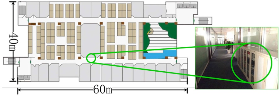
A floor plan of our experimental office building. There are some file cabinets along corridors. For example, one of them is represented by a green circle.
Performance of attitude detection
This experiment examines the performance of the proposed attitude detection scheme under different experimental scenarios. We divide the testing scenarios into five holding manners: UFH attitude, upward forward non horizontal (UFNH) attitude, upward and leftward or rightward or backward (ULRB) attitude, screen facing downward attitude, and swing hand attitude. The UFH and UFNH attitudes are all holding smartphones in accordance with the user’s forward moving directions and with screens facing upward. The only difference between them is whether the smartphone is held horizontally. The ULRB attitude appears when a user holds a smartphone with the screen facing upward, but its pointing direction is leftward, rightward, or backward comparing to the user moving direction. When a smartphone is in UFH or UFNH attitudes, magnetic information can be utilized in positioning, whereas when a smartphone is in the ULRB, downward, or swing hand attitudes, the measured azimuths are not in accordance with the user moving directions; therefore, particles will move toward wrong directions, causing serious PE. Therefore, the positioning system needs to stop magnetic positioning and switch to attitude-free positioning schemes.
For each testing scenario, we collect 350-step data, then we label them with relative ground truth. Finally, the collected data are used as input into the attitude detection algorithm to calculate the predictions. Figure 15 depicts the prediction results. Most of the ground truth UFH and UFNH attitudes are correctly predicted, but about 5% data are wrongly detected as upward non forward (UNF) attitude. This is because when users turning a corner, the features of UFH and UFNH attitude are likely to be affected, thus causing wrong detections.

Attitude detection statistics. The x-axis reveals the four types of predictions. There are five attitude testing scenarios, represented as the color bars. The NU stands for non-upward attitudes.
We also calculate the receiver operating characteristic curve (ROC) of the four classifiers used in the attitude detection scheme, as shown in Figure 16. In our experiment, the area under roc curves (AUC) of the non-upward attitude classifier is 0.99, the AUC of UNF is 0.95, the AUC of UFNH is 0.98, and the AUC of UFH is 0.97, proving the high-performance of the proposed classifiers.

ROC of the attitude detection scheme.
Motion model evaluation
Step-length estimation comparison with existing methods
The experiment evaluates the system performance by using PDR and particle filtering. For this purpose, we only keep particles movement and floor plan restriction. Because better estimation model generates more accurate step lengths, an improved positioning accuracy is expected. In order to reduce the influences from other factors, the experiment lets a user walk around a
The experiment results are shown as a cumulative distribution function (CDF) in Figure 17. The static model performs worst because it estimates step lengths as a constant value (0.65 m). Then, the experiment adds a normal distribution random variable to the mean step length in terms of a normal distribution model. The model’s positioning performance improves because the small random variable scatters particles when the user walks, thus enhancing the possibility to reset particles at corners. The frequency model 50 considers the step-length variations relevant to step frequencies, hence further improves system accuracy. Finally, the proposed scheme enables the system to evolve itself; therefore, it performs the best.

The CDF of PDR positioning with different step-length estimation methods.
Direction estimation evaluation
This experiment tests the performance of the proposed direction estimation method. It uses the same data of the step-length estimation experiment. In the direction estimation experiment, we use the static step-length model for both the azimuth compensated estimation method and without the compensation method. Therefore, the azimuth compensation becomes the main factor to influence the positioning accuracy. As Figure 18 reveals, the azimuth compensated method performs much better than the other does. The proposed system is able to compensate particle direction, thus improving positioning accuracy significantly.

The CDF of PDR positioning with and without azimuth compensation.
The training of the magnetic field positioning model
There are two different corridors in our test bed, having

Interpolated magnetic strength map. Different colors represent magnetic strengths. The unit is

Interpolated azimuth map. Different colors represent magnetic azimuth angles. The unit is degree.

Interpolated polar angle map. Different colors represent magnetic polar angles. The unit is degree.
Key parameters evaluation of the mass-centered weight update scheme
This part shows the key parameters evaluation process of the proposed mass-centered weight update scheme. Considering that the evaluation process of the azimuth and polar angle data is similar to the strength data evaluation process, this part only shows the case of the strength data analysis.
Evaluations of sliding window length W
This experiment randomly initializes award parameter K and award threshold parameter T. Then, increasing the window length W, the changing of the positioning performance is evaluated. As Figure 22 reveals, the positioning performance from 1 step to 5 steps is approximated and is better than the performances obtained evaluating from 6 steps to 15 steps, because the longer window length needs more particles to cover the increasing diversity. Therefore, with a limited particle population, the performance drops as sliding length enlarges. According to the results, the article selects the best-performed three steps as the window length for the rest of the experiments.

CDFs of different sliding window lengths. Weight award parameter U and threshold parameter T are randomly set to 0.7 and 0.5, respectively. Performances from 1 step to 5 steps are better than that of 6 steps and 15 steps. The three-step window is the best configuration.
Evaluations of award parameter K
Having found a proper sliding window length, this experiment tries to search a good award parameter. The experiment increases award parameter K from a small value to large values, then it compares the performance of the parameters. This experiment evaluates a wide range of K value, and results from typical values are shown in Figure 23. The result shows that a small award parameter led the magnetic field positioning scheme to have a little effect on particle weights update. Consequently, it is necessary to keep award parameter big enough. Experiment results also reveal that too big award parameters have little improvement on the performance too. According to the results, the article set award parameter K to 70.
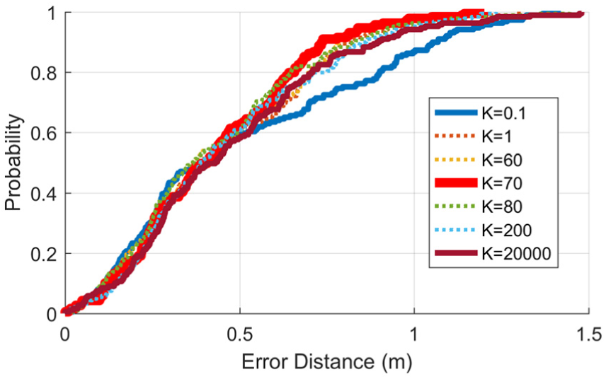
CDFs of different award parameters. The sliding window length is set to three steps according to the previous experiment. The weight threshold parameter T is randomly initialized to 0.5. Performances from K = 1 to 20,000 are similar, K = 0.1 shows the worst result, and K = 70 performs the best.
Evaluations of award threshold T
Keeping W and K static, all the threshold T possibilities are evaluated. The influence of these thresholds to the positioning performance is shown in Figure 24. If the threshold is too big, the selectiveness of the scheme will be weakened, because most of the particles will be awarded with the same weight. In contrast, a too small threshold increases the risk of assigning outlier particles with too big weights, causing particle degeneracy. According to the experiment results,

CDFs of different award thresholds. The sliding window length is three steps. The weight award parameter K is set to 70 according to the previous experiment. Performances from T = 0.01 to 0.5 are similar, T = 1.1 shows the worst result, and T = 0.05 performs the best.
Comprehensive positioning performance analysis
Performance of different users
This experiment tests the system’s adaptability to different genders, heights, and weights. First, the experiment chose a testing path in the testing environment, and then let six users walk along the testing path and finally calculated the PEs. The results are shown in Figure 25. The performances of the six users are all similar to the training data collecting user, showing that the proposed step-length estimation method and magnetic field weights update method are able to be fit to different users.

Adaptability tests on different users. The fourth user is the user who collects the magnetic fingerprints as training data. Character F stands for a female and M for a male.
Performance of different smartphones
The sensor gains and printed circuit board (PCB) layout are different from different smartphones. This aspect may affect the positioning performance. This experiment evaluates the proposed positioning system considering four different smartphones. Collecting testing data along the same testing path involving the same user, it is evaluated as a comparison between different smartphone performances. In this experiment, the user utilized Huawei P9 to collect indoor fingerprint and generate positioning model. The other smartphones calculate positioning results using the same positioning model generated by the Huawei P9. As Figure 26 reveals, the performance of the other three smartphones is similar to the training data collection smartphone P9, showing the good generalizability of the proposed system.

Device heterogeneity analysis.
Comparison with existing positioning schemes
In order to evaluate the positioning accuracy of the proposed solution, this part compares the proposed system with state-of-the-art systems (FreeLoc, 52 HiMLoc, 53 and Magicol 25 ). FreeLoc is a calibration-free Wi-Fi positioning algorithm across different devices. As Figure 27 shows, the accuracy of Wi-Fi positioning method is larger than 10 m at 80%. In our solution, we use the FreeLoc scheme to initialize the start point of particles. The HiMLoc combines PDR and Wi-Fi positioning via a particle filter, and the result shows that the floor plan information restricts particle movements inside paths, and therefore improves the positioning accuracies. Magicol is a particle filter–based indoor positioning system, using magnetic field as location fingerprints. This method leverages the DTW algorithm to update the weight of each particle. Figure 27 illustrates that the performance of the Magicol and the proposed solution can be divided into two segments. When the accuracy probability is less than 60%, the Magicol is more accurate than that of our proposed solution. On the contrary, when the accuracy probability is greater than 60%, our solution performs better. Because the DTW algorithm always tries to find the best match between real-time and model fingerprints, it improves the chance to find the best match and also increases the risk of mismatches. On the contrary, our solution imposes more step-length restrictions to the particle estimations; therefore, it reduces the searching scope of particles, thus making the result more stable.
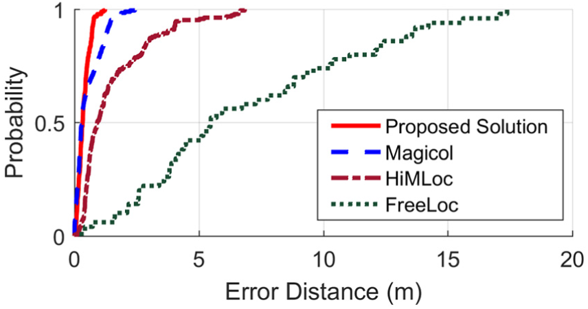
Positioning performance comparison with existing systems.
In order to test the computational efficiency of the proposed scheme, we compare it with the state-of-the-art Magicol method that utilizes DTW to update particle weights. Given the number of particles is N, the magnetometer sampling frequency is
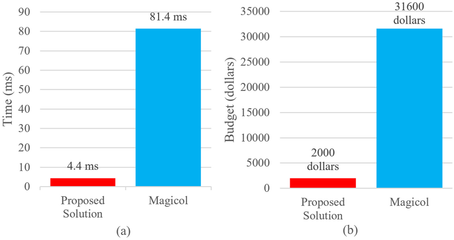
Computation cost comparison with the Magicol system: (a) mean computation time and (b) monthly hardware budget for 10,000 users.
Performance at different scenarios
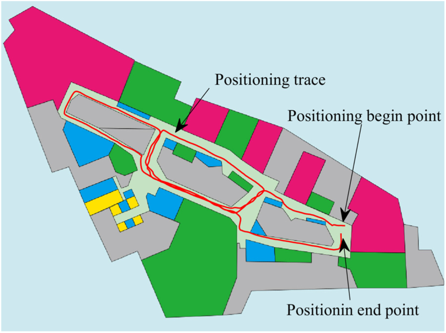
In order to test the performance of the proposed positioning system in different scenarios, we selected the third floor of a shopping mall and deployed our system in it. We sampled data of main corridors of this floor, one corridor only sampling once. Therefore, it took about 30 min to sample the floor. We ask a user to walk inside the testing floor in order to examine the positioning performance. The ground truth of the user is shown in Figure 29. The user walked 524 steps in total. We conducted the experiment at a weekend; therefore, there are many people shopping in the market, and the sampling and testing process was usually interrupted by nearby people.

Experiment scenario of a shopping mall. The blue line is the ground-truth test path that a user walks.
Figure 30 reveals the positioning trajectory of the user, and Figure 31 shows the CDF of the positioning results. The results are not as good as that of the office environment because the path of the shopping mall is wider than the office, thus providing less magnetic position features and floor plan restrictions. Another reason is that crowded environments affect the sampling and positioning process, thus introducing more errors.
Positioning trajectory of the evaluation path.

The CDF of the proposed positioning system in the shopping mall.
Conclusion
The proposed positioning system is based on indoor magnetic field and inertial measurement units. It has several advantages, including infrastructure-free, low deployment cost, and high spatial resolutions. However, traditional magnetic field–based positioning systems have some drawbacks, as a heavy magnetic fingerprint comparison workload and an insufficient analysis of magnetic field signals. In this article, we analyze the models of pedestrian user motions and propose a mass-centered weight update scheme to decrease the fingerprint comparison workload. Based on the fact that UFH attitude is the most common posture when users reading location fixes from smartphone screens, we also propose the attitude detector to enable the system to choose automatically between full magnetic field positioning and attitude-free positioning methods. Experiments reveal that the proposed attitude detection scheme is available to effectively distinguish smartphone’s UFH attitudes from other attitudes. Furthermore, the proposed magnetic scheme works well when different users and devices are considered. Finally, the system has a comparable accuracy with other positioning systems, but the proposed system is 18 times faster than the traditional DTW approach applied on magnetic field traces.
Footnotes
Handling Editor: Yu Wang
Declaration of conflicting interests
The author(s) declared no potential conflicts of interest with respect to the research, authorship, and/or publication of this article.
Funding
The author(s) disclosed receipt of the following financial support for the research, authorship, and/or publication of this article: This work was supported in part by the National Key Research and Development Program (2018YFB0505200), the National Natural Science Foundation of China (61872046), the BUPT Excellent PhD Students Foundation (CX2017404), and the Open Project of the Beijing Key Laboratory of Mobile Computing and Pervasive Device.