
Abstract
The design of a robot system for assembling numerous parts, including screws, washers, nuts, and other irregular parts, is important in manufacturing. Although a robot can flexibly manipulate various parts with the aid of vision and force sensors, some challenges remain, for example, precise orientation and precise insertion when uncertainty exists in the positioning and manipulation of irregular objects. In this work, we present a method to design the orienting strategy for positioning the irregular parts based on the constraints formed by the fixture, thus the irregular parts such as the motor can be precisely localized only with the robot squeezing actions. We then develop a peg-in-hole insertion strategy using the force constraints formed by the environment, where fewer robot actions are required to insert the peg, thus enabling efficient and precise peg-in-hole insertions. Finally, we developed a robot assembly system with three robots from Universal Robots to perform all the assembly tasks, including picking, holding, placing, and inserting. Experiments on the assembly of a belt drive unit reveal the efficiency of the proposed method.
Introduction
Robot assembly shows excellent performance in manufacturing because it reduces the proportion of defective products. 1 In the past 30 years, robot assembly strategies combining vision and force sensors have been widely studied.
In a robot assembly system, vision is usually employed to estimate the object’s pose for picking. For example, Liu et al. 1 calculated the target position by applying a fast directional chamfer matching algorithm; hence, the target was selected based on visual information. Dupuis et al. 2 discussed the three-dimensional vision-based picking of a randomized connecting rod. Sansonia et al. 3 developed a laser vision system for picking up piled objects. Su et al. 4 developed a vision-based bin-picking system for picking and reorienting piled objects and constructed a constraint region to design the reorienting strategy. Domae et al. 5 created a segment-based stereovision approach based on a versatile volumetric vision system for assembly. This approach was used to determine and monitor the location and orientation of items with curved surfaces. Although many vision-based positioning algorithms have been proposed to guide robot manipulation in complex environments, problems still exist in assembly tasks. For example, the current pose of the object is possibly not suitable for insertion. Thus, the robot must reorient the object into the expected goal pose. Although passive compliant motion strategies, such as regrasping, 6 reorienting, 4 or feeding, 7 have been proposed to deal with the reorientation problem, some of them need to generate sequential robot postures for iterative object reorientation, which is time-consuming.
Once the object’s pose has been obtained, researchers have employed a force-based controller to guide the robot’s motions. Xie et al. 8 described the assembly of a miniaturized gear using a hybrid vision–force control method. They employed visual feedback to coarsely locate the parts and guide grasping and then developed a fuzzy proportional–integral–derivative controller to control the contact force. Zheng et al. 9 achieved a peg-in-hole assembly using hybrid vision–force guidance, where the rough adjustment of the robot was guided by an eye-to-hand vision system, and the position and orientation were precisely adjusted as per the force and torque information, respectively. They experimented with a maximum clearance of 0.5 mm between the peg and hole. Ma et al. 10 studied the assembly of two small cylindrical components, where two microscopic cameras were employed to provide visual information in the aligning stage for assembly, and a micro force sensor was used to perceive the contact forces in the insertion stage. Gorjup et al. 11 calculated the target position using one camera and a three-dimensional computer-aided design model and then employed a force controller to compensate for errors in calibration or positioning. Kim et al. 12 presented a vision–force-guided assembly system using a force sensor and two cameras. The target pose was estimated from a two-dimensional image, and the object was assembled with the proper force. Wu et al. 13 used an implementation approach fusing signals of vision detection and fuzzy force to realize peg-in-hole insertion. YOLO v.3 was applied as the visual detection network for rough alignment, and a semi-supervised learning network was used to optimize the hole-searching routine.
Irregular objects, which have special shapes and are difficult to fix or orient to the desired pose, are widely used in manufacturing. For example, the “L shape” holder plate and the eccentric shaft motor shown in Figure 1 are typical irregular parts. In assembly, orienting an irregular object such as an eccentric shaft motor to the desired pose for robot insertion is a difficult task. Although various reorienting methods had been proposed to deal with the reorientation problem, most of them needed to generate sequential robot postures for iterative object reorientation. And, in the inserting stage, force-based robot control methods usually perform the insertion by precisely adjusting the object’s position and orientation as per the force and torque information, where the complex adjustments are time-consuming and suffer from the resolution of the force sensor and the noise on the sensor. To solve the problems, We present a method to design the orienting strategy for positioning the irregular part using the constraints formed by the potential energy of the fixture, thus the irregular part such as the motor can be precisely localized only with the robot squeezing actions and the fixture. That is, the fixture can reorient the motor to a determined pose that corresponds to the minimum of the constraints. We develop a peg-in-hole insertion strategy using the force constraints formed by the environment, where several simple robot actions are required to insert the peg. The force constraints describe the relationships between the contact forces and peg-hole states, and the minimum of the constraint region relates to the state in which the peg has been inserted into the hole. Thus, we can precisely and quickly insert the peg into the hole by pushing the peg-hole state approach to the bottom of the force constraints with fewer robot actions and coarse sensing. We design a robot assembly system with three robots to perform precision tasks, including peg-in-hole insertion, screw fixing, and irregular plate fixing.
The remainder of this paper is organized as follows. The second section describes the development of the assembly system. The third section introduces the object reorientation strategy. The fourth section presents the assembly strategy that combines compliant and sensor-based motions. The fifth section provides the experimental results of the assembly of a belt drive unit. The sixth section presents directions for future studies.
System overviews
Problem statement
The design of a flexible robot system for performing complex assembly tasks in which various parts including irregular parts were automatically assembled by robots remains challenging. The belt drive unit shown in Figure 1 was the challenging task in WRS 2020 competition, 14 which consisted of small parts and irregular parts such as threaded screws, soft parts, gear units, washers, and nuts. The parts tray on the left supplied the parts used in the task, while the screws were placed on the right tray. The pose of all parts should be estimated by the camera mounted on the robot. The holder plate should be firstly fixed on the workbench. Then one robot arm should hold the plate, while another robot arm used the screwdriver to fix it on the workbench screws. The motor was required to be fixed on the plate using six screws. Thus, a small positioning error or an excessive force caused by misalignment in the assembly would damage both the parts and the robot system, even causing the failure of the task. To be concluded, the difficulties of the assembly of the belt drive unit were (a) a variety of parts with different shapes and different characteristics needed to be oriented and assembled precisely, and complex manipulations such as screwing screws and assembling belts should be performed. (b) The assembly required more than one robot arm to cooperate with the manipulations. (c) The assembly task was with high-precision requirements, for example, the clearance between the peg and the hole is 0.03 mm.

(a) shows the parts for assembling, and (b) shows the assembled belt drive unit.
2.2 System design
We designed a flexible assembly system using three universal robots to perform the assembly of the belt drive unit, as illustrated in Figure 2. The assistant robot (UR-1) was used to pick the workpiece. The assembly robot (UR-2) was equipped with a force/torque sensor and used to insert the peg into the hole. The screwing robot (UR-3) was used to fasten the screw with the help of electric screwdrivers. Note that we choose to use UR robots as they are lightweight robotic arms and use less electricity than traditional industrial robots. And, UR robots are re-deployable and fast to reprogram, giving us the flexibility to change setup. Thus, we select the UR robots to perform the assembly in this work. Of course, other kinds of robots also be used to assemble the task with the proposed method. Charge-coupled device (CCD) cameras were used to capture images of the worktable and then send them to the host computer. Thus, the pose of the target workpiece on the worktable can be estimated by using the template-matching method.

Assembly system with three UR robots: (a) model of the system and (b) real system.
A robot-layered software structure was designed for assembly. It contained five layers, as shown in Figure 3. The hardware layer provided the hardware components, including the three UR robots, electric screwdrivers, three types of grippers, an air pump, cameras, and a force sensor. The driver layer provided the drivers of the hardware, which included RTDE and URX libraries for the driving commands of the robots from Universal Robots. In addition, drivers for cameras, force sensors, and Robotiq grippers were presented. The planning layer contained control and path-planning algorithms, used to achieve robot position and compliance control. A multiarm cooperative planner lies in this layer. It was used to plan the trajectory of the three robots and prevent collisions. The algorithm layer included the template-matching algorithm for target recognition, task information for specific assembly task recognition, and the force control algorithm for performing force-guided compliant motion in the constraint region. The user layer was realized based on Qt, which was used for convenient human–computer interaction to complete different assembly tasks.

Software architecture.
Object pose reorientation
Initial pose estimation using vision
The first important step of the flexible assembly was to locate the objects with the image and then detect the geometry properties of the parts. The vision system not only needed to identify each part on the worktable but also needed to precisely estimate the position of the hole on the part. That is, the vision system had the requirement of the field of view and the detection precision. Thus, we employed two types of cameras, where CCD cameras mounted on the end-effector of the robot arm the system was employed to detect the pose and size of the parts. Once the part’s pose had been detected, the position of the holes on the part for screwing also can be obtained. In this work, we used the shape information to identify the parts from the image and used the pyramid-based image matching method 15–17 to speed up the search process. The estimating process is given in Figure 4.

Pose estimation using pyramid-based image matching method.
The pose estimation algorithm first built the tree structure of the pyramid model to layer the template. A template that achieved a certain similarity was classified as a class, which was denoted by “aspect.” We stored the “aspect” on the next floor of the pyramid and then calculated the image similarity again until the final pose of the target was obtained on the top of the pyramid. Based on the pyramid-based image matching method, we matched the input image with the generated hierarchical shape template. The hierarchical matching method would improve the matching efficiency. Figure 5 gives some examples of shape-matching results, where the target objects were, respectively, matched to their shape template in the library. Note that the time cost for the pose estimation of the “L shape” holder plate and other shapes is about 100 ms.

The results of shape matching.
Pose reorientation using fixture constraints
In some cases, the current pose of the object was not the desired pose for the robot’s next task; hence, we needed to reorient the pose of the object. Given the current and desired poses of an object, the goal of reorientation is to determine a sequence of robot manipulations that change the object from its current pose to the desired pose. Reorientation is an important skill when a robot cannot directly pick an object with the desired pose owing to kinematic constraints and collisions. In our previous work, 18 we developed grasping algorithms to eliminate the uncertainties of the object inside the gripper by applying the constraints formed by the gripper. However, orienting an object to the desired pose in only one grasp was difficult. As shown in Figure 6, the gripper has difficulty grasping an eccentric shaft motor so that it attained a pose in which all six holes of the motor should be aligned with the corresponding holes on the holder.

Eccentric shaft motor fixed on the plate, where six threaded screws were used to fasten the motor on the holder.
In this work, we designed a fixture and a robot action sequence to reorient the motor to the desired pose using the constraints formed by the potential energy of the fixture. Note that we also designed another fixture to reorient the “L shape” holder. We used a vision system to capture the image of the motor and the holder, estimated the initial pose of the motor using a shape detection method, and identified the hole of the holder using an ellipse detection method. The gripper was then guided to pick up the target part from the worktable. The key problem in this stage was to grasp the motor in the desired position for alignment with the hole on the holder. Therefore, the motor should be reoriented to the desired position for insertion. In this section, we discussed a method for reorienting an eccentric shaft motor using the constraints formed by the fixture. We used the information about the distance between the two parallel jaws upon closure to distinguish the orientation. We briefly described the design of the fixture used to reorient the eccentric shaft motor.
As shown in Figure 7(a), the eccentric shaft of the motor was supported by the supporting point, where the gravitational force decreases the pitch angle,
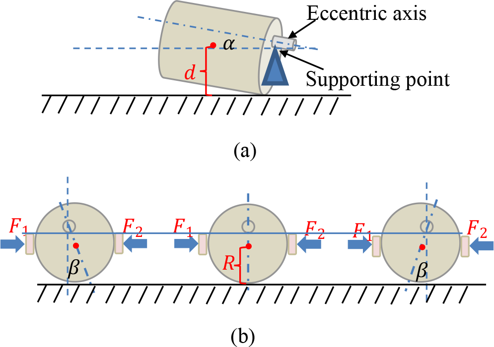
(a) Eccentric shaft motor, where d denoted the height of the center of the motor, and
A potential energy function was defined as

where R was the radius of the motor, G was the gravitational force on the motor,
By applying (1), we can build a graph of Ep , as shown in Figure 8. When squeeze and gravitational forces were applied to the eccentric shaft motor, the state of the motor approached the bottom of the graph. As the orientation of the eccentric shaft motor was fixed at the bottom of the graph, the eccentric shaft can be precisely inserted into the hole on the holder, as shown in Figure 9(d). In this case, the six threaded holes of the eccentric shaft motor aligned with the related hole on the holder and then were fastened by using threaded screws. Figure 9(a) to (c) shows the process of picking the motor, placing it on the fixture, and squeezing the fixture by using the jaws of the two-fingered gripper.

Graph of the potential energy function of the motor inside the reorienting device.
As shown in Figure 9, the support base was composed of a shaft supporter and two semicircular squeezing plates. The supporter was used to locate the position of the eccentric shaft, and blocks were applied to eliminate the pose uncertainties of the motor, as shown in Figure 9(a). When the gripper squeezes the blocks, the rotation and movement of the eccentric shaft motor were restrained, as shown in Figure 9(b).

(a) Robot picking and placing the part in the reorienting device, (b) motor support point device for reorienting the motor, (c) gripper squeezing the blocks for fixing the motor, and (d) motor aligned with the hole.
Figure 9(b) to (d) shows the process of placing the motor on the fixture, reorienting the motor, and picking the block to restrain the motor. We were able to use vision to determine whether the six holes on the motor aligned with the six corresponding holes on the holder.
Precise alignment using force control
We previously developed a robot assembly strategy using active and passive compliant motions when the initial pose of the shaft was unknown. 19 However, the assembly process with the two compliant motions was time-consuming because the controlled motion was designed in two sub-configuration spaces, and the insertion direction was downward. In this work, we discuss a more general case in which the direction of insertion was not perpendicular to the earth.
Once the rough pose of the peg was estimated visually, we applied an active compliant control method to perform robot insertion precisely and efficiently. We designed a force-guided compliant motion in the constraint region, in which only several contact states are estimated from the force information to guide the robot’s motion. Thus, we can quickly and precisely insert the nut into the hole with fewer robot actions and coarse sensing (Figure 10).

A nut was inserted into the hole with fewer robot actions and coarse sensing.
We analyzed the contact forces and frictional forces at the two-point contact states, as shown in Figure 11. We assumed that the two symmetric points on the end surface of the peg are C
1 and C
2,
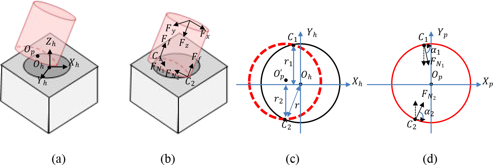
(a) Coordinate frame built on the hole, where Oh
was the center of the upper surface of the hole and Op
was the center of the end surface of the peg, (b) contact forces between the peg and the hole, (c) projection of the end surface of the peg, where the red circle was the end surface of the peg, black circle was the upper surface of the hole, dotted red elliptic was the projection of the end surface of the peg on the
If the active force was applied by the robot along the −Zh -axis, we can obtain


where
We assumed that the pitch angle of the peg related to the Zh
-axis was

Here,

Hence,

Substituting (7) into (3) yields

For simplicity, we assumed that

Because

The graph of

Graph of
Similarly, we can establish the following relationship

The graph of

Graph of
Figures 12 and 13 show that forces Fx
and Fy
decrease if Op
approaches Oh
. In Figure 12, Fx
reached its minimum when

Force-based assembly process.
We considered each Cartesian variable independently so that the control input to the robot can be written as follows
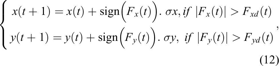
where
Based on (12), the force-guide assembly process is provided in Figure 14.
Experiments
Figures 15 to 18 showed the entire process of the assembly of the belt drive unit using the developed assembly system. The vision system first identified the target part from the worktable and then estimated its pose in the robot coordinate frame. In this study, the shape information was used to identify the parts from the image, and the pyramid-based image-matching method was employed to accelerate the search process. 15,16 Estimating the pose of the rectangular parts was easy because they have some typical features, such as edges and circles. In this work, a camera mounted on UR3-1 was used to determine whether the threaded holes on the L-shaped part and the peg were aligned. Then, UR3-2 mounted on the screwdriver was used to turn the screws one by one.
As shown in Figure 15(a), the vision system mounted on the robot end effector identified and estimated the position of the screw holes; then, UR3-1 holds the plate, and another UR3-2 uses the screwdrivers to fasten the screws. In Figure 15(b), the eccentric shaft motor was assembled using the method described in the third section. UR3-1 inserts the shaft motor into the holder, and UR3-2 uses an electric screwdriver to fasten the screw.

(a) Fixing the plate on the workbench with two robots; (b) fixing the motor on the plate with two robots.
As displayed in Figure 16(a) and (b), UR3-1 inserts the nut into the hole and then UR3-2 uses screwdrivers to fasten the screws under the guidance of the vision system. In this step, the force controller proposed in Figure 14 was used to achieve precise alignment. Note that the clearance between the nut and hole is approximately 0.03 mm and is hard to be inserted only with a position-control approach.

(a) Inserting the nut into the hole; (b) fixing the nut on the plate with screws.
The contact force measured in the assembly of the peg is shown in Figure 17, where the green, orange, and blue lines represent the measured forces along x
-, y-, and z-directions, respectively. For example, the contact force in the Xh
-the direction was initially large, indicating that the large position error on the Xh
-axis should be decreased. Thus, the peg moves along the
The positions of the peg on the coordinates of the hole are shown in Figure 17(b) and (c). The peg moved along the Xh
- or Yh
-direction according to the measured forces, that is, the peg moved along −Xh
if

(a) Measured forces in the assembly, (b) peg movement along Xh
-axis, and (c) peg movement along
Figure 18(a) and (b) show the insertion of a peg using the proposed force controller, which is similar to the assembly of the nut described in Figure 16.

(a) Inserting one long peg into the hole; (b) inserting another long peg into the hole.
Conclusion
To make industrial robots programmable universal machines that can be easily and quickly configured and reconfigured into systems without incurring a high cost for system integration, we developed an assembly strategy using reorientation and sensor-based motion control methods. Then, we designed a flexible robot assembly system to perform the challenging assembly task.
The system included three UR robots, two CCD cameras, one force/torque sensor, two Robotiq grippers, and three specially designed electric screwdrivers. The three robots were employed to perform different tasks: UR-1 was used to pick the workpiece, UR-2 was used with a force/torque sensor to insert the peg into the hole, and UR-3 was used to turn the screw with the help of electric screwdrivers. CCD cameras were used to capture an image of the worktable, and a force controller combined with the constraint formed by the environment was designed to achieve precision assembly tasks. Minor visual errors were compensated for by force control. The proposed force-based assembly method enabled the system to achieve a high accuracy and success rate during task execution. The designed quick-change grippers and reorientation strategies maximized their versatility in performing different manufacturing tasks. The effectiveness of the designed system was verified in the WRS2020 competition.
In our future work, we will discuss the assembly of more complex parts, such as gears and cables. We plan to design a more flexible force-guided alignment algorithm to control the compliant motion of the robot.
Footnotes
Acknowledgment
The authors thank Yan Meng and Lili Wang for their help on the simulations and experiments of the work.
Declaration of conflicting interests
The authors declared no potential conflicts of interest with respect to the research, authorship, and/or publication of this article.
Funding
The authors disclosed receipt of the following financial support for the research, authorship, and/or publication of this article: This work was supported in part by NSFC under Grant Number 62273343, supported by the Beijing Natural Science Foundation under Grant Number L201019, and supported by the Key Laboratory of Spaceflight Dynamics Technology Foundation under Grant Number KGJ6142210210311.
Appendix
We have performed a comparative experiment using the classic impedance control method. The impedance model used in force tracking is normally selected as a linear mass-spring-damper system; hence, the dynamic relationship between the robot movement error and the external force perturbation can be written as 20,21
with
where M,
Figure 19 shows the force tracking results of the impedance controller, where the solid lines represent the desired forces and the dotted lines represent the measured forces, where we set