
Abstract
Lower-limb exoskeletons have attracted considerable interest because they can provide impaired individuals with the ability to walk upright. Trajectory generation of walking gait is a crucial issue for lower-limb exoskeletons that has not yet been satisfactorily solved. The purpose of this article is to study a stable gait generation method considering the subjective walking intention. Inspired by the motion synergy between crutches and lower limbs, a stable gait generation method for flat-ground walking was proposed for a lower-limb exoskeleton. The motion synergy in the sagittal plane between the crutch-pitch-angle and step length was validated using theoretical and experimental methods. The synergistic relationship between the maximum crutch-pitch-angle and step-length coefficient was established and optimized. Based on the synergistic relationship, the gait trajectory of the exoskeleton with variable step length can be instinctively generated with a crutch swing. The gait stability of the human-exoskeleton system was modeled and analyzed. Consecutive walking experiments were conducted on flat ground in which a compact lower-limb exoskeleton and pair of instrumented crutches were employed. The results demonstrate that gait based on the synergistic relationship is effective and stable, thereby verifying the feasibility of this human-in-the-loop gait generation method.
Introduction
The lower-limb exoskeleton has received considerable research attention because it can provide impaired individuals with the ability to walk upright, which has been verified by clinical trials. 1 –4 Over the past decade, lower-limb exoskeletons for walking assistance have constantly evolved, and many have been developed and described in the literature. 5 –8 The currently available devices, such as Rewalk™ (ReWalk Robotics Ltd, Yokneam, Israel), 9,10 Ekso™ (Ekso Bionics Holdings, Inc., Richmond, California, USA), 11,12 HAL® (Cyberdyne Inc., Tsukuba, Japan), 13 –15 Indego® (Parker Hannifin Corp., Cleveland, Ohio, USA), 16,17 Mina v2 (Florida Institute for Human and Machine Cognition, Pensacola, Florida, USA), 18,19 and WalkON Suit (Sogang University, Seoul, South Korea), 20,21 have different design specifications in terms of overall configuration, weight, and functionality. Many commonalities of these devices are listed as follows. The system weights of these powered devices are between 10 kg and 35 kg. Their bilateral hips and knees are driven by a DC motor via specially designed transmission mechanisms. A compact computer is more likely to be employed as the main controller of the system. Basic tasks in daily life, such as flat walking, standing up, and sitting down, can be achieved. Crutches or canes should be applied for the impaired pilot when walking with the lower-limb exoskeleton.
Lower limbs are the primary means to satisfy locomotion needs for the humans. Studies have shown that the skeletal system constitutes a mechanism that can potentially be reproduced mechanically, and walking patterns are measurable, predictable, and repeatable. A mechanical reproduction of these mechanisms and their movement are useful in kinematic chains for exoskeletons. 22 –25 The dominant goal of a lower-limb exoskeleton in impaired individuals is an additional locomotion function. Therefore, the generation and control of gait motion are crucial issues in exoskeleton development. A set of predefined joint angle trajectories is applied in position-based controls. 7 The predefined trajectories can be adjusted offline or online as required. 10,11,14,16,18,20 The different motion states and switches between them are triggered by external equipment. To maintain balance, crutches (or canes) occupy the hands and forearms of the pilot. Thus, buttons, switches, screens, or other equipment are installed on the crutches. 12,13,18,20 The pilot could control the motions of the exoskeleton by manipulating the crutches. In these situations, the crutch acts as a manipulator.
Thus, crutches can be more functional and informative. Several instrumented crutches have been developed for signal measurements and motion monitoring. Sardini et al. and Lancini et al. 26 –29 developed instrumented crutches that could monitor axial forces, shear forces, and tilt angles. The crutches can provide clinicians with quantitative information on the contributions of the upper limbs and internal loads during walking. Similarly, Seylan and Saranli, 30 Chamorro-Moriana et al., 31 and Chen et al. 32 designed instrumented crutches to accurately provide information about the loads exerted on crutches during aided gait. Li et al. 33 proposed a walking control method for paraplegic patients wearing a powered exoskeleton. Two pressure sensors were embedded into the gripper of the crutch, and the index finger was inserted between the two sensors to control the stride. An electrode array was attached to the middle finger to provide electric stimulation as feedback while holding a crutch. However, the operation of the exoskeleton becomes more complex and burdensome with Li’s method. Hassan et al. 13,34,35 found sufficient coupling between lower-limb motion and cane movement. Based on the inter-limb locomotor synergies, a motion generation pattern of the affected leg for hemiparesis was proposed using the motion information of the unaffected leg and an aid crutch. This method provides an effective reference for gait generation and control of the exoskeleton.
In this study, we propose a human-in-the-loop walking gait generation method for a lower-limb exoskeleton based on instrumented crutches. In this method, the step length can be adjusted based on the pitch angle of instrumented crutches. The gait generation process is intuitive and humanlike. Similar to natural walking, the step length of the pilot was coupled with the swing angle of the upper limb (or crutch). Therefore, the pilot can release the burden of manipulation using the synergy between the lower limb and crutch.
The remainder of this article is organized as follows. The second section presents the stable gait generation method for lower-limb exoskeleton based on instrumented crutches. The third and fourth sections explain the walking experiments and results. Finally, conclusions are provided in the final section.
Methods
Related work
We developed a compact lower-limb exoskeleton for walking assistance (CLEWA), as shown in Figure 1. Its pilot is expected to have sufficient upper-body strength to maintain balance with the crutches. The CLEWA is modular-designed, and its first prototype weighs 10 kg. The bilateral hips and knees of the CLEWA were actuated using steel cables driven by a DC motor in the sagittal plane. Each joint can provide up to 20.6 N·m of torque continuously and 96.0 N·m of torque instantaneously based on a 48 VDC bus voltage. The continuous speed of each joint is 33 r/min. The main controller combines TMS320F28335 (Texas Instruments, Dallas, TX, USA) and STM32F301 (STMicroelectronics, Geneva, Switzerland), in which the control strategy runs based on a finite-state machine. Based on the reference trajectories, the walking gait can be generated online via the velocity, step length, and step height parameters. 36
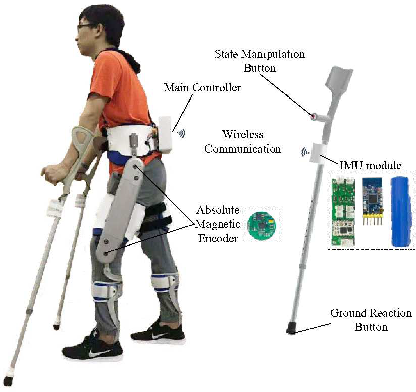
Compact lower-limb exoskeleton for walking assistance (CLEWA) and instrumented crutches.
The CLEWA motion sensor system comprises two main components: two inertial measurement unit (IMU) modules fixed on both crutches and four encoders fitted on both hips and knees, as shown in Figure 1. The IMU module detects the motion angle of the corresponding crutch, acquires contact information from the trigger on the tip of the crutch, and wirelessly sends the data to the main controller. The state information of the manipulation button fitted on the crutch was processed and sent to the main controller via the IMU module. The main controller computes the data according to the states and sends control commands to the joint actuators that are wired by the controller area network (CAN) bus. The absolute magnetic encoder was specially designed and employed to detect the angle positions of the bilateral hips and knees. The motion data were sent to the main controller wired by the CAN bus. The IMU module was designed based on STM32F301 and MPU9250 (InvenSense, Sunnyvale, California, USA), and its wireless communication was realized via the ZigBee module DL-30 (Deeplink, Shenzhen, China), in which the chip was a cc2530 (Texas Instruments, Dallas, Texas, USA). The absolute magnetic encoder was designed based on the MLX90316 (Melexis, Ypres, Belgium).
Motion synergy between crutch and lower limb
To control the lower-limb exoskeleton based on an instrumented crutch, the motion relationship between the crutch and lower limb should be analyzed and established. We focused on the relationship between the crutch-pitch-angles and joint positions in the sagittal plane because the CLEWA is actuated in the sagittal plane. This relationship is similar to that between the upper and lower limbs, considering that the crutch can be an extension of the arm. A flat-ground walking experiment was conducted, and the pitch angles of one crutch in the sagittal plane were gathered, as shown in Figure 2(a). The CLEWA reference joint positions, which were designed based on the torque compensation control, 36 are shown in Figure 2(b). In Figure 2(a), the average values of the crutch-pitch-angles periodically vary between 0° and 14°, and the variation trend approximates a sinusoid. An analogous variation trend was also observed in the values of hip position.

Crutch angles and reference joint positions during flat-ground walking. (a) Pitch angles of the crutch. (b) Reference joint positions of lower-limb exoskeleton.
The motion relationship between the crutches and lower limbs can be analyzed via principal component analysis (PCA). PCA is a statistical method and has been used to approximate the inter-joint synergies by linear combinations of degrees of freedom. 37,38 In PCA, four cases were investigated: (1) crutch-pitch-angles, hip positions, and knee positions (C-H-K); (2) crutch-pitch-angles and hip positions (C-H); (3) crutch-pitch-angles and knee positions (C-K); and (4) hip and knee positions (H-K). The results are shown in Figure 3. The first principal components for the above four cases represented 61.97%, 99.27%, 91.65%, and 64.94% of the variation, respectively. The motion couplings of C-H (99.27%) and C-K (91.65%) were greater than 90%, especially in the case of C-H. Therefore, the results indicate that the motions of the crutch and lower limb are synergistic in the sagittal plane during flat-ground walking.
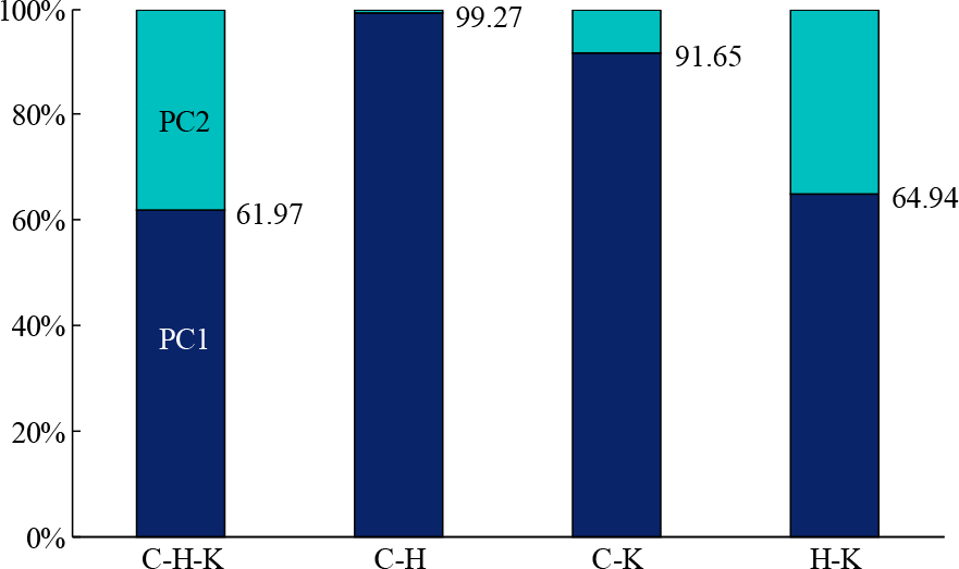
Principle component (PC) ratios for four cases: (1) crutch-pitch-angles, hip positions, and knee positions (C-H-K); (2) crutch-pitch-angles and hip positions (C-H); (3) crutch-pitch-angles and knee positions (C-K); (4) hip and knee positions (H-K).
Step length was positively correlated with hip swing amplitude. Thus, the relationship between the crutch-pitch-angle and step length can be established and applied to walking gait generation. An intention trigger experiment was conducted to define the range of crutch-pitch-angles during flat-ground walking. Five participants (male, average height 176.2 cm, average weight 68.4 kg) were involved in the intention trigger experiment. Each participant had three steps (small, medium, and large steps) four times, in which the step length was decided by the participants. The results for the maximum pitch angles of the crutch in one step are shown in Figure 4.

Maximum crutch-pitch-angles in one step.
The boxplot shows the minimum, maximum, median, upper quartile, and bottom quartile of the maximum crutch-pitch-angle values in three types of steps, and the average value (symbol +) of all values. The maximum crutch-pitch-angle
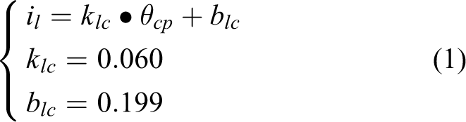
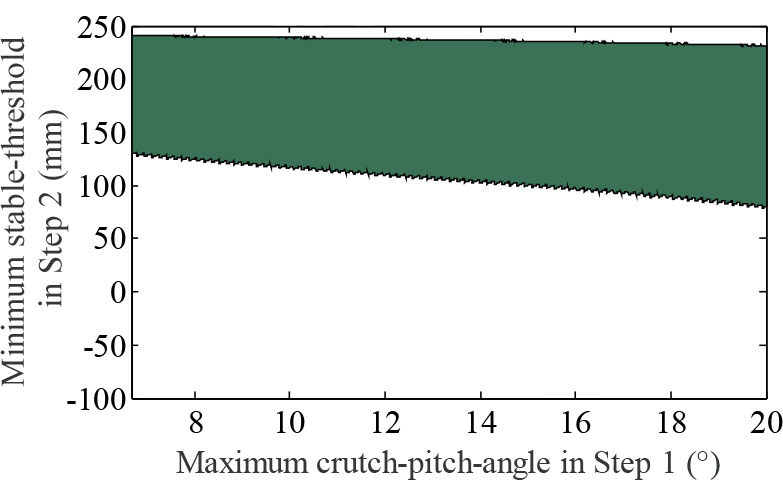
The bisection method was applied to calculate the boundary between these three steps. The maximum crutch-pitch-angles are divided into three sections corresponding to the three types of steps: 6.68°–8.72°, 8.72°–13.16°, and 13.16°–20°. The step-length coefficient il was employed to describe the ratio of the step length relative to the reference trajectory in Figure 2(b). The value range of the step-length coefficient is set from 0.6° to 1.4°, which corresponds to the maximum crutch-pitch-angle of 6.68°–20°. The linear relationship between the maximum crutch-pitch-angle and step-length coefficient was established using equation (1). Through the established synergistic relationship, the exoskeleton gait trajectory with variable step length can be instinctively generated with a crutch swing
Gait stability analysis
Stability is important for the guidance and evaluation of gait quality. Gait trajectory optimization is instrumental in enhancing the pilot’s stability and safety and releasing the manipulation burden. The center of gravity (CoG; the projection point of the CoG of the entire system on the ground) was employed to analyze gait stability. A stability analysis model was established as shown in Figure 5. In this model, the exoskeleton and crutches were tightly attached to the human body. A crutch is regarded as an extension of the arm. Stability analysis of the diagonal gait was conducted in the sagittal plane. A support polygon is formed by contact points between the feet, crutches, and ground. If the CoG is within the range of the support polygon, the system is verified to be stable; otherwise, pilots will be at risk of falling during flat-ground walking.

Model of the gait stability analysis. (a) Kinematics model of the human-exoskeleton system. (b) Centroids distribution of the human-exoskeleton system. (c) Diagonal gait and CoG during flat-ground walking. CoG: center of gravity.
According to Figure 5(b), the masses

Furthermore, to analyze the gait stability quantitatively, a stable threshold was employed to represent the ability of the gait to resist external interference. The stable threshold

where
For example, in the case of the reference trajectory, the step-length coefficient il
is 1.0, and the crutch-pitch-angle
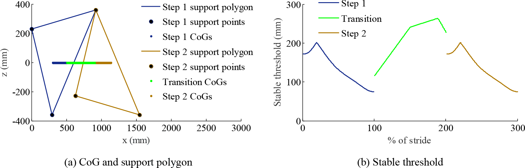
Stability analysis of the sample gait in two consecutive steps. (a) CoG and support polygon. (b) Stable threshold. CoG: center of gravity.
In addition, the crutch-pitch-angle

Minimum stable thresholds of all cross-combinations in two consecutive steps. (a) Gait adjustment based on the synergistic relationship. (b) No gait adjustment.
As shown in Figure 7(a), a synergistic relationship model was employed. The system can maintain stabilization in every cross-combination in two consecutive steps. The minimum stability threshold was within the range of 28–240 mm. Gait stability analysis indicates that the exoskeleton can generate a gait trajectory in consecutive walking by utilizing the synergistic relationship model without additional crutch adjustment. However, as shown in Figure 7(b), the stability of the subsequent step is degraded when the
Synergistic relationship optimization
According to Figure 7(a), the minimum stable threshold was 28 mm. Mathematical optimization of the synergistic relationship was conducted to further improve the stability threshold. Based on equation (1), the minimum stable thresholds of gait with different
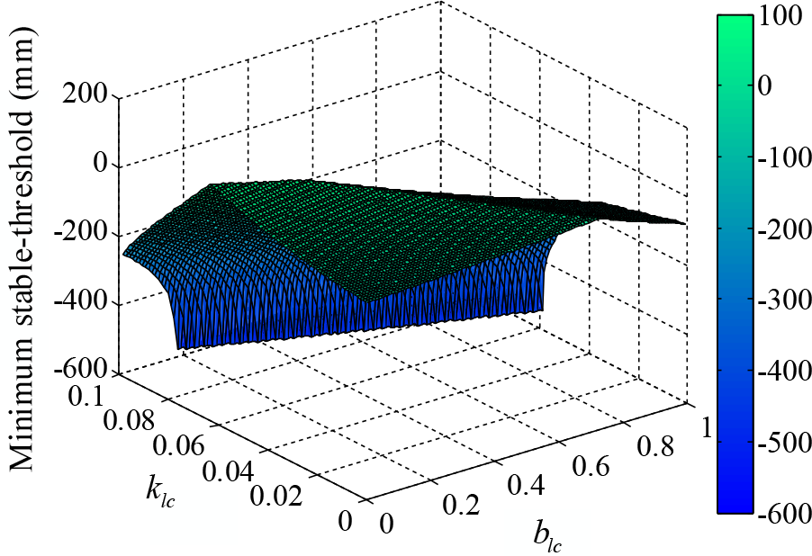
Minimum stable thresholds of the gait with different

Minimum stable thresholds of all cross-combinations in two consecutive steps based on the optimized synergistic relationship.
The results showed that the minimum stable threshold was 75 mm. Meanwhile, gait stability was improved significantly by the optimized synergistic relationship model. The feasibility of the gait generation method based on the synergistic relationship was theoretically validated.
Experiments
To verify the feasibility and performance of the proposed gait generation method, walking experiments on an exoskeleton with a pilot were conducted. In the experiments, CLEWA and instrumented crutches which are introduced in the “Related work” section were used. The pilot (healthy male, 176 cm, 70 kg) wore CLEWA and instrumented crutches, and walked 50 steps on flat ground using a diagonal sequence. Meanwhile, the lengths of the steps were random, as per the pilot’s wish.
In the experiments, a flowchart of control system for one step is shown in Figure 10. First, the crutch wirelessly sends the crutch-pitch-angle to the main controller when the crutch swing is completed. Subsequently, the actuators of the hips and knees receive the joint positions from the main controller after triggering the lower-limb swing. In the complete step above, the synergistic relationship model and inverse kinematics model were calculated for the control system. Two types of walking experiments were conducted, in which synergistic relationship models before and after optimization were employed.

Flowchart of control system for one step.
Results
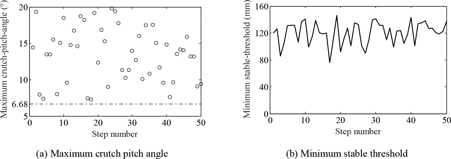
In the first walking experiment, the synergistic relationship shown in equation (1) was employed. In addition, the crutch-pitch-angles and corresponding minimum stable thresholds of 50 steps were obtained. As shown in Figure 11, the stable thresholds of the entire system were maintained above 29 mm. The results indicate that CLEWA can generate a stable gait in consecutive flat-ground walking by utilizing the synergistic relationship model without additional crutch adjustment. Furthermore, when the values of the crutch-pitch-angles in two consecutive steps have large differences, the stable threshold of the system significantly decreases. Therefore, steps 29–33 were selected as extreme cases, and the stability of these five consecutive steps was analyzed. The crutch-pitch-angles and corresponding step-length coefficients of these five steps are listed in Table 1.

Results of 50 steps in the first walking experiment employing the synergistic relationship before optimization. (a) Maximum crutch-pitch-angle. (b) Minimum stable threshold.
Maximum crutch-pitch-angles and step-length coefficients of steps 29–33 in the first walking experiment.

As shown in Table 1, the combinations of five consecutive steps are large, small, small, and large. The corresponding joint positions, CoG, and stable threshold of the exoskeleton system during these five steps were obtained, as shown in Figure 12. The general trends in the joint positions were consistent, and the position amplitudes were proportional to step length. The stable threshold results indicate that the system can maintain stabilization in these five steps. In addition, the results show that the large–small step combination of the exoskeleton is a relatively risky situation, and the minimum stable threshold in this situation is 29.2 mm.
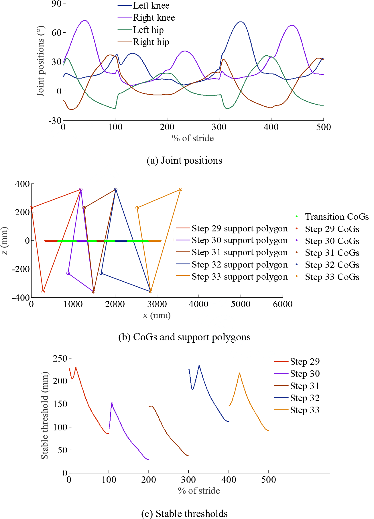
Stability analysis results of steps 29–33 in the first walking experiment as a special case. (a) Joint positions. (b) CoGs and support polygons. (c) Stable thresholds. CoG: center of gravity.
In the second walking experiment, the optimized synergistic relationship model in equation (4) was employed. Similarly, the crutch-pitch-angles and corresponding minimum stable thresholds of 50 steps were obtained, as shown in Figure 13. Compared to the results of the first walking experiment, the stable thresholds above 76 mm were significantly larger than those in Figure 11. Meanwhile, the amplitude values of the minimum stable thresholds are smaller than those shown in Figure 11. The results indicate that CLEWA generates a more stable gait in consecutive flat-ground walking based on the optimized synergistic relationship. Steps 15–19 are selected as the extreme case, and the stability of these five consecutive steps is analyzed similarly. The crutch-pitch-angles and corresponding step-length coefficients of these five steps are listed in Table 2.
Results of 50 steps in the second walking experiment employing the optimized synergistic relationship. (a) Maximum crutch-pitch-angle. (b) Minimum stable threshold.
Maximum crutch-pitch-angles and step-length coefficients of steps 15–19 in the second walking experiment.

As shown in Table 2, the five consecutive step combinations were large, large, small, and large. The corresponding joint positions, CoG, and stable threshold of the exoskeleton system during these five steps were obtained, as shown in Figure 14. The stable threshold results show that the large–small steps combination of exoskeleton still is a relatively risky situation, however, the minimum stable threshold in this situation is 76.3 mm, which is larger than 29.2 mm in Figure 12. The stable threshold is maintained within an appropriate range, even under the risky step combination. In experiments, the feasibility of the instinctive gait generation method based on the synergetic motion was validated. Gait in consecutive flat-ground walking utilizing this synergistic relationship was effective and stable.

Stability analysis results of steps 15–19 in the second walking experiment as a special case. (a) Joint positions. (b) CoGs and support polygons. (c) Stable thresholds. CoG: center of gravity.
Conclusions
In this study, a stable gait generation method for a lower-limb exoskeleton based on synergetic motion is proposed. The motion synergy between the crutch and lower limb was obtained using the PCA method. The synergistic relationship between the maximum crutch-pitch-angle and step-length coefficient was established based on the experimental method. Based on the synergistic relationship, the gait trajectory of the exoskeleton with variable step length can be instinctively generated with a crutch swing. Furthermore, the gait stability of the human-exoskeleton system is analyzed in the following three cases: no gait adjustment, gait adjustment according to the synergistic relationship, and gait adjustment according to the optimized synergistic relationship. Gait stability analysis indicates that the exoskeleton can generate a stable gait trajectory in consecutive walking by utilizing the synergistic relationship, and the gait stability improved significantly by the optimized synergistic relationship model.
Two types of walking experiments for a compact lower-limb exoskeleton were conducted, in which synergistic relationship models before and after optimization were employed. The results demonstrate that the exoskeleton can generate a stable gait during consecutive flat-ground walking based on a synergistic relationship. The human-exoskeleton system can maintain stabilization, and the minimum stable threshold is improved from 29.2 mm to 76.3 mm because of the synergistic relationship optimization.
The stable gait generation method based on synergistic relationship in this article can achieve stable walking assistance, as well as partial hybrid zero dynamics method, 39 zero moment point based body-exoskeleton interference compensation method, 40 and the reference trajectories online modification method. 41 By comparison, the main feature of the method proposed in this article is that it comprehensively considers the pilot’s motion state and subjective walking intention and can generate a more natural walking gait based on the wearer’s inter-limb synergies. Furthermore, the method can achieve better controllability of the exoskeleton by the wearer’s walking intention and improve the adaptability to the wearer’s walking habits without using complex models.
The synergistic relationship in this article is established with the step length, and it is relatively insensitive to step height. Therefore, the synergistic relationship method is limited to the situation of flat ground. In the future, we wish to explore the effectiveness of this proposed method for community locomotion with different types of slopes, stairs, and obstacles.
Footnotes
Declaration of conflicting interests
The author(s) declared no potential conflicts of interest with respect to the research, authorship, and/or publication of this article.
Funding
The author(s) disclosed receipt of the following financial support for the research, authorship, and/or publication of this article: This research was funded by the National Natural Science Foundation of China (grant numbers 52105016 and 61961015), the NSFC-Shenzhen Robotics Research Center Project (grant number U2013207), and the fellowship of China Postdoctoral Science Foundation (grant number 2022M710957).
Appendix 1
Calculation of stable thresholds in consecutive walking.

| 1: Solve by equation (1) or equation (4) |
| 2: , , , ← , , , , , by forward kinematics model |
| 3: |
| 4: ← , ; |
| 5: ← , , by numerical approximation method |
| 6: |
| 7: , , , ← , , , , , , by inverse kinematics model |
| 8: ← , , , , , , , , , ; |
| 9: ← , , , , , , , , , , by forward kinematics model |
| 10: Solve by equation (2) |
| 11: Solve dm by equation (3) |