
Abstract
Space-saving, high-density stereo parking lots have gained considerable attention because of emerging limitations in ground and underground space. In this article, a novel arm-type single stereo parking lot is proposed to realize convenience and environmental friendliness. Many technical difficulties should be resolved before the safety performance of the stereo parking lot can be enhanced. Therefore, the structural characteristics, the load state and the motion situation should be analysed by numerical simulation to develop a reasonable design scheme. Finite element analysis was conducted on the steel tray platform, and kinematic analysis was performed on the end of novel arm-type single stereo parking lot. As a result, the position, velocity and acceleration curves as well as the maximum workspace were demonstrated by simulation in Pro/E. The simulation results demonstrate the correctness and accuracy of the stereo parking lot under motion mode feasible in residential areas and agency units and that the proposed parking lot can become popular in practice because of characteristics such as simplicity, convenience, easy development and promotion.
Introduction
Recent urbanization and economic development have led to a boom in the automobile industry, resulting in a sharp rise in static traffic problems, that is, parking problems.1,2 For example, from 1978 to 2002, the number of privately owned cars increased by approximately 20 times. The number of vehicles in operation worldwide surpassed the 1 billion-unit mark in 2010 for the first time ever. Therefore, parking lots have become an important object class in many applications. In view of the limitations of ground and underground space, space-saving, high-density stereo parking lots have gained considerable interest as a research target.
As a kind of robot, the kinematics study of the parking lot is necessary. Robot kinematics describes the changes in the joint and the end executor during the process of robot movement, which is the basis of robotics. Kinematics is generally categorized into two aspects: forward kinematics and inverse kinematics.1–4 Forward kinematics is the process of finding the position and posture of the end executor of the robot after the parameters of the connecting rods and the variables of the joint are obtained. In contrast, inverse kinematics involves solving the joint variables of the robot on the basis of the known position and posture of the end actuator. In robot kinematics research, homogeneous transformation matrix is commonly adopted to describe the relationship between adjacent connecting rods and subsequently establish the kinematics equation.
According to previous studies, the inverse solution of the kinematics of the parking lot can be determined by many different ways, including geometric method, iterative method, analytical method and the combination of these methods. The geometric method is suitable for kinematics analysis with simple structure, less degrees of freedom and obvious geometrical relationship among the agencies. Iterative method is characterized by a relatively large amount of calculation, slow calculation speed and low accuracy, which are the factors that influence the control requirements of the robot. Analytical method was established based on the robot kinematics equation. Both sides of the equation are then multiplied with the inverse matrix of the homogeneous transformation matrix between the adjacent connecting rod. Finally, the required joint variable is isolated according to the equality of the corresponding matrix elements on both sides of the equation.
Trajectory planning is the fundamental step of bottom of the planning, and it is based on the kinematics and dynamics of the robot. Trajectory planning is the basis not only of robot trajectory tracking control but also of performing the tasks. In practice, according to the different requirements of parking lots, the trajectory of a parking lot can be divided into the point-to-point movement and continuous trajectory. Regardless of the type, no matter what kind of trajectory, it is necessary to guarantee the smooth, quick and accurate movement of the parking lot.
Motion simulation and finite element analysis are indispensable steps in studying the robot. To realize quick analysis of robot modelling, plan out the optimal trajectory and realize the optimization design of the parking lot structure and the controller. Visualized computer simulation is used to simulate the characteristics of the robot’s dynamic characteristics, which is helpful for analysing the working space of the parking lot and for verifying the rationality of the trajectory and control algorithm of the parking lot. Therefore, this approach improves the shortcomings and insufficiency of the design timely as well as avoids unnecessary losses in the actual operation.
In this study, a novel stereo parking lot was designed to realize convenience, energy conservation and environmental friendliness. The analytical method was used to analyse the motion process. The forward and inverse solutions of the kinematic equations of the stereo parking lot were determined to obtain the optimal results of tracking planning. Motion simulation was conducted using the Pro/E three-dimensional mapping software. This new stereo parking lot is very suitable for residential areas and units.
Characteristics of the novel designed arm-type stereo parking lot
Structure
The structure of the newly designed arm-type stereo parking lot is shown in Figure 1. The junction plate and movable arm are joined with the fixed support (component 10 in Figure 1). The truss arm is then connected to the movable arm. Finally, the steel tray plate is joined with the truss arm.5–14
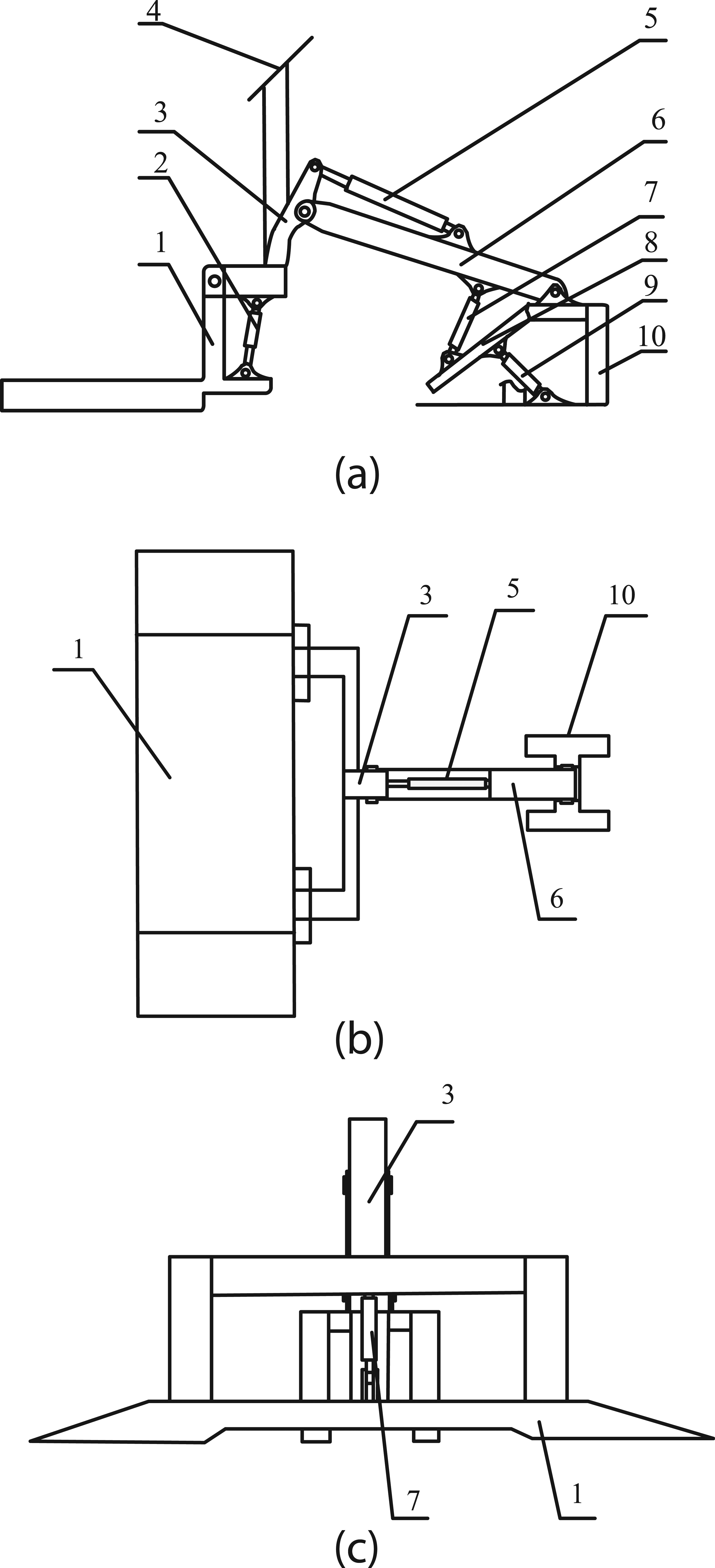
Structure of the newly designed arm-type stereo parking lot: (a) main view, (b) top view and (c) left view.
To balance the gravity centre of car, two hydraulic cylinders are designed (component 2 in Figure 1) for controlling the steel tray platform. In addition, three hydraulic cylinders are used to connect the different components (components 5, 7 and 9 in Figure 1). Moreover, an additional solar panel is introduced in the arm-type stereo parking lot to make it energy-efficient and environmentally friendly.
Parameters
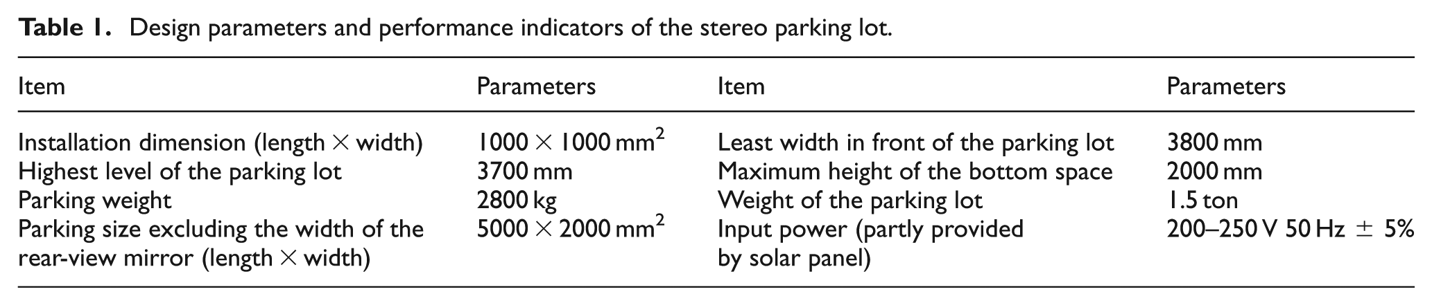
The design parameters and performance indicators are shown in Table 1. To reduce welding stress and prevent welding deformation, the pressure type and steel structure materials are required in the manufacture of the components. Moreover, the welding cast method is used in the special position of the movable arm with high stress to improve the fatigue strength and rigidity of the components. In particular, all the components near the hinge parts should be made of steel to ensure the strength of the welding.
Design parameters and performance indicators of the stereo parking lot.
To attain energy efficiency, the sound and light alarm system, the infrared sensing system, the lighting system and its control system are all supported by the solar panel to conserve electric power. Moreover, the in-position locks, power outage locks, running fault suspension system, electrical overload protection device, photoelectric switch, buffering and alerting systems are all considered in the design to guarantee the safety of the parking lot.
Motion analysis of the novel designed stereo parking lot
Pose matrix
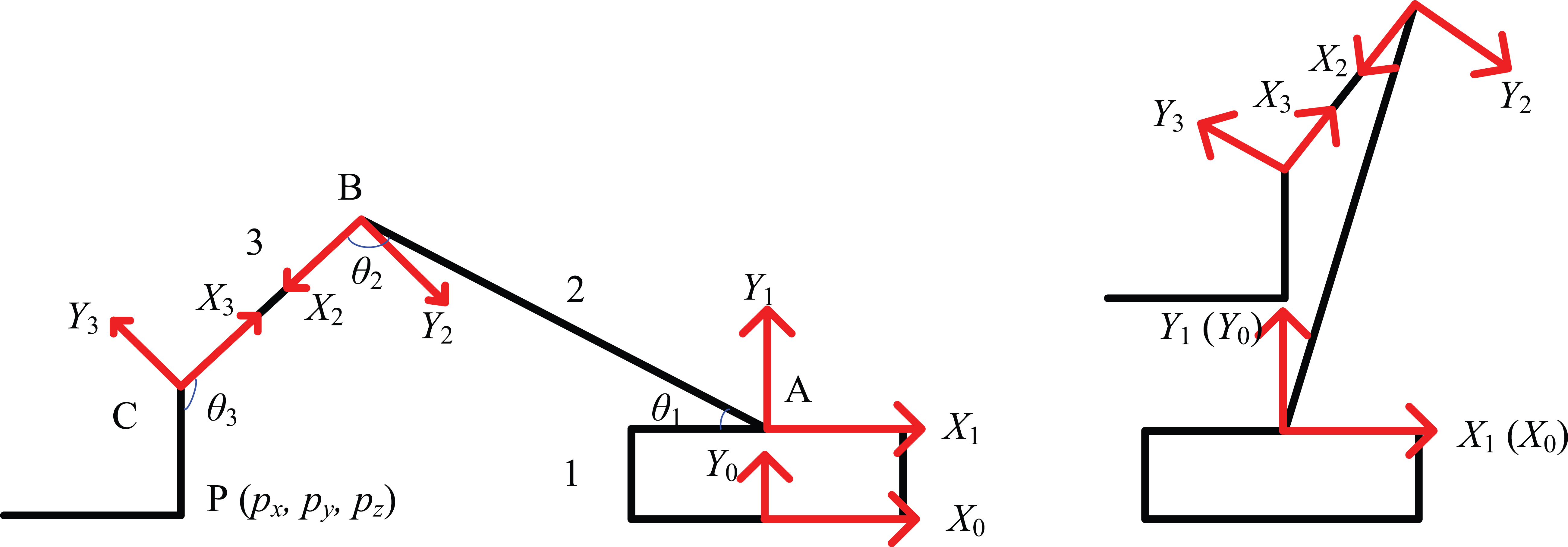
Three virtual coordinate systems are set in the model of the parking lot (Figure 2) to describe the degree of freedom, establish the pose matrix and finally realize the motion simulation. First, the OX 0 Y 0 Z 0 coordinate system is the joining point. Second, the OX 1 Y 1 Z 1 coordinate system is built on the joining point between the fixed support and the movable arm. Third, the OX 2 Y 2 Z 2 coordinate system is located on the joining point between the movable arm and the truss arm. Fourth, the OX 3 Y 3 Z 3 coordinate system is on the joining point between the truss arm and the steel tray platform.
Virtual coordinate systems set in the model of parking lot.
As shown in Figure 2, P(px , py , pz ) is the coordinate of the setting point P on the steel tray plate. θ 1 is the included angle between the movable arm AB and the horizontal plane, θ 2 is the rotation angle between the movable arm AB and the truss arm BC and θ 3 is the angle between the truss arm BC and the steel tray plate CP.
Forward solutions of kinematic equations of stereo parking lot
Denavit and Hartenberg proposed a matrix method (D-H method) of establishing possessed coordinates for each joint chain rods to describe the relationship between the translation and rotation of adjacent rods. 15 According to the special structure of the proposed novel design of the stereo parking lot, we used the D-H method to model the design and then validated the correctness of the established model. In this article, we verified the correctness of the forward kinematics and investigated its inverse kinematics to improve the success rate of the automatic grasping of objects. 15
The 3 degrees of freedom set in the present stereo parking lot are all characterized by having rotational structure, whose characteristic parameters are as shown below:
The distance from Y i−1 to Y i following the direction of X i−1 represents the length of the connecting rod a i ; the second and third lengths of the connecting rod are a 2 = h and a 3 = k, respectively.
The angle around Y i−1 following the direction from Y i−1 to Y i is defined as the torsion angle. Given that all the connecting rods are in the same plane, all coordinate system origins are in the same plane. Therefore, α 1 = α 2 = α 3 = 0.
The distance from X i−1 to X i following the direction of Z i is defined as the offset d i . Similarly, the values of the offset d i are all equal to 0, that is, d 1 = d 2 = d 3 = 0.
The angle around Z i−1 following the direction from Y i−1 to Y i is defined as the coupler-angle.
According to the above coordinate systems, the parameters of 3 degrees of freedom parking device are obtained and shown in Table 2.
Denavit–Hartenberg parameters of connecting rods.

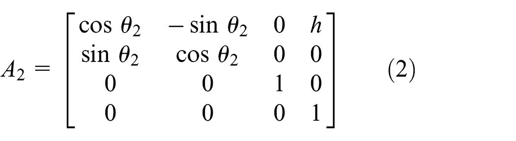
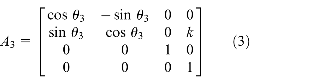
According to the parameters shown in Figure 2, the homogeneous transformation matrices of the three connecting rods were obtained as follows

On the basis of equations (1)–(3), the R transformational matrices were obtained and shown as follows
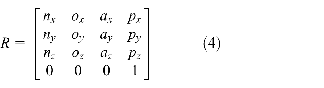

where

The R transformational matrix describes the positional relation of the steel tray platform relative to the reference coordination system, which is the theoretical foundation of the kinematics simulation analysis of the stereo parking lot.
Inverse solutions of kinematic equations of stereo parking lot
The inverse solutions of the kinematic equations are the process of looking for the value of the joint variables θ 1, θ 2 and θ 3 when the pose of the steel tray platform has been pre-set. 16 To conveniently solve for the equations, two intermediate variables, namely, r and ϕ, were introduced into the equations. The inverse solutions are obtained with the use of the following triangle substitute

where

(a) The value of θ 2
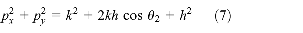
Substituting equation (6) in equation (7) gives

(b) The value of θ 1
The inverse transformation

Element (2, 4) at both ends of matrix equation (9) was set with a corresponding equality, and the following was obtained
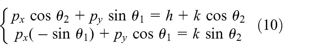
Equations (6) and (8) were plugged into equation (9) to gain θ 1

(c) The value of θ 3
Let

Element (1, 4) and Element (2, 4) at both ends of matrix equation (12) were set with a corresponding equality, and the following was obtained

where

that is

Therefore, the value of θ 3 was then obtained as follows

Various results can be obtained for the inverse solutions of the kinematic equations of stereo parking lot. However, some of the results cannot be realized because of the limitations in the designed structure of the present parking lot. For example, the connecting rod cannot move in the entire range of 360°. Thus, an optimal solution should be selected to satisfy the requirements of the working.
Trajectory planning
The purpose of trajectory planning is to design the parameters of the steel tray platform during the working process, including the displacement, the speed and the accelerated speed, among others, and to find the optimal track from the initial state to the target state. The expecting pose can be attained by reasonably controlling the movements of the connecting rods. 17 Trajectory planning is generally performed using three methods: three polynomial interpolation, high-order polynomial interpolation and parabola over linear interpolation.
The positional constraint conditions of the movement locus function are θ(0) = θ 0, θ(tf ) = θf , θ′(0) = 0 and θ′(tf ) = 0. The polynomial that satisfies the above constraint conditions are as follows

The speed of the connecting rod was obtained as the first-order derivative of equation (15)

The accelerated speeds of the connecting rods were obtained as the derivative of equation (16)

The constraint conditions were introduced into equations (15)–(17), and the values of a 0, a 1, a 2 and a 3 were then obtained as follows

As shown in Figure 3, the waves of tracks 1 and 2 are obvious during the movement, whereas track 3 is stable to the target position. Therefore, for the sake of safety, track 3 is considered the optimal choice and the final objective of the trajectory planning.

Movement track of connecting rods.
Finite element calculation and analysis of steel tray platform
Deformation of steel tray platform
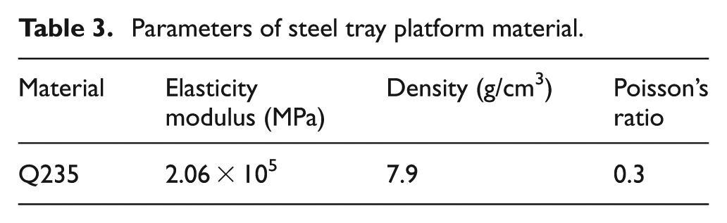
Currently, steel Q235 is typically chosen as the material for steel tray platforms. Its material properties are shown in Table 3. 18
Parameters of steel tray platform material.
The steel tray platform component is very important for the parking equipment. Thus, ANSYS software is adopted to simulate its motion and load stress states to optimize the structure of the parking equipment. To ensure that the simulation results are as realistic as possible, the finite element model is only simplified as necessary.
The red arrow area is where the auto tire is in contact with the steel tray platform and where the static load is added. The grid of the steel tray platform entity model and the deformation after loading are shown in Figure 4.

Static load analysis of the steel tray platform.
Figure 4 shows that the values of deformation of the steel tray platform increase from a fixed position to the outside. On this foundation, the stress distribution of the steel tray platform was further studied.
Load stress of the steel tray platform
The steel tray platform is made of plastic material. The stress analysis on the steel tray platform is subject to the fourth strength theorem of material mechanics. Figure 5 shows the first principal stress distribution of steel tray platform.
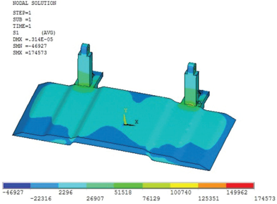
First principal stress distribution of the steel tray platform.
Equivalent stress distribution of the steel tray platform in the Y-direction is shown in Figure 6.
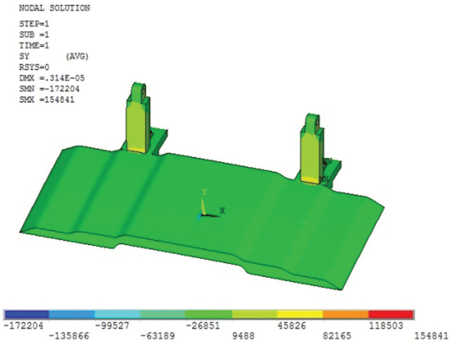
Equivalent stress distribution of the Y-direction of the steel tray platform.
From the perspective of the distribution of stress, when the vehicle was parked in the steel tray platform, the first principal stress of the steel tray platform was 0.174573 MPa. Meanwhile, it yielded a higher equivalent stress in the Y-direction, that is, 0.154841 MPa. Both measurements are smaller than the tensile strength 380 MPa of Q235. Therefore, the strength of the steel tray platform is sufficiently large to meet the design and operation requirements.
According to the principal stress pattern, the maximum stress occurs in the joint of the car plate and the load table column. However, the stress here can be improved by thickening the ribbed plate between the column and the steel tray plate.
Motion simulation of stereo parking lot
Motion simulation
The three-dimensional entity model and the motion simulation are conducted using the Pro/E three-dimensional mapping software. The three-dimensional entity model of the parking lot is shown in Figure 7 (left section). After the entity model was established, interference inspection was conducted to avoid any interference problems during operation. Finally, the motion track was confirmed to realize the safety and efficiency in Figure 7. Figure 8 shows the installation of the parking equipment in the residential area. Figure 9 shows the double stereo parking equipment. The use of the device is a times more than the ground parking lot, but it still cannot solve the space utilization of the concave and convex sections above the flower beds and lawns of residential areas and agency units. Thus, a novel arm-type single stereo parking lot can be placed in the concave and convex sections of flower beds and lawns. As a result, such an approach not only meets the requirements of parking but also avoids disturbing normal natural plant growth. When the car is parked in the air, the more that it would not affect the traffic, and it can avoid scratches and window breakage. The device is characterized by having a simple and compact structure, convenient and quick operation, and it is very suitable for residential areas and agency units.
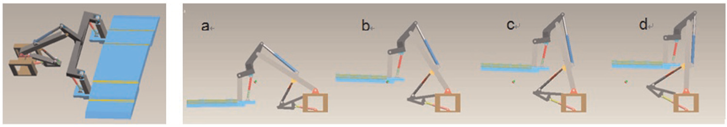
Three-dimensional entity model and motion track of the parking lot. The left section of this figure is the three-dimensional entity model of the parking lot. The right section is the motion track of the parking lot: (a) the initial situation when the car moved onto the steel tray platform, (b) and (c) the process of moving car to the target location and (d) the final position after parking.

Parking equipment installation in a residential area.

Double parking equipment for a residential area.
Motion process analysis
To clarify the motion process of the parking lot, the characteristics of the five hydraulic cylinders during the first 8 s at the start of the parking process are analysed and shown in Figure 10. 19 The displacement curve shown in Figure 10(a) supposes that the truss arm hydraulic cylinder and the swing arm hydraulic cylinder move directly. Therefore, their accelerated speeds are 0 in Figure 10(b), and their moving speeds are constant in Figure 10(c). Meanwhile, the displacement of the levelling hydraulic cylinder increases with a positive accelerated speed as shown in Figure 10(b) and increasing speed as shown in Figure 10(c). In contrast, the accelerated speed of the steel tray hydraulic cylinder was negative and constant, indicating that the displacement declined while the parking lot was rising.

Motion process analysis of the five hydraulic cylinders: (a) displacement, (b) acceleration, (c) speed and (d) force.
The force curves of the five hydraulic cylinders during the first 8 s of lifting are as shown in Figure 10(d). At the beginning of the parking process, the levelling hydraulic cylinder was stretched. Thus, the force value was positive. However, the other three kinds of hydraulic cylinders were compressed. The force they faced was actually stress, which was expressed as negative in Figure 10(d). During the parking process, the different components faced different stresses. The force of the levelling hydraulic cylinder increased along with lifting. This finding proves that the levelling hydraulic cylinder plays the dominant role during the parking process. The force suffered by the steel tray platform hydraulic cylinder remained stable and was equal to the weight of the car.
In contrast to the abovementioned hydraulic cylinders, the force of the swing arm hydraulic cylinder and the truss arm hydraulic cylinder decreased with time. Therefore, the compression force exerted on them was reduced with lifting.
Conclusion
A novel design of an arm-type stereo parking lot is introduced in this study. The objective of the proposed parking lot is to solve the problem of static traffic problem – parking problems in large cities. The single parking lot is suitable for the family or institutions. First, the safety is considered by in-position lock systems and so on. The energy supply can be saved by introducing solar panels into the design. The bottom space could still be used as lawns, thus promoting environmental friendliness and enjoyment for people. Second, finite element analysis was conducted to explore the state of the load distribution of the steel tray platform. Third, motion analysis was conducted to explore the mechanism during the working of the parking lot and to optimize the trajectory planning and the motion track. On one hand, the optimal results of tracking planning were obtained on the basis of the forward and inverse solutions of the kinematic equations of the stereo parking lot. On the other hand, the motion process is simulated by the Pro/E three-dimensional mapping software and is analysed based on the displacement, force, speed and acceleration. The results suggest that the force of levelling hydraulic cylinder increased along with lifting, manifesting that during the parking process, the levelling hydraulic cylinder plays the dominant role. The force suffered by the steel tray platform hydraulic cylinder remains stable, whereas the force of the swing arm hydraulic cylinder and the truss arm hydraulic cylinder decreases with time. The simulation results prove that the correctness and accuracy of the stereo parking lot under motion mode are feasible in residential area and units.
Footnotes
Academic Editor: Yong Chen
Declaration of conflicting interests
The author(s) declared no potential conflicts of interest with respect to the research, authorship and/or publication of this article.
Funding
This work was supported by the Fundamental Research Funds for the Central Universities No. 2014XS25.