
Abstract
Locomotive robot based on tensegrity has recently drawn much attention due to its lightweight and flexibility. This article presents an improved numerical model for locomotive tensegrities. The previously used bar element for struts is replaced by beam element, and rigid joint element is used to consider more details of the tendon–strut connections. The vector form intrinsic finite element (VFIFE) method is adopted to formulate the numerical model and carry out the simulation. The improvement of the proposed model on the prediction of feasible rolling gaits is quantitatively verified by experiments on a six-strut locomotive tensegrity. Mann–Whitney U test is adopted, and the p value between the experimental success rates of the gait primitives generated by the improved model and the rates of the gait primitives generated by the previous model is
Keywords
Introduction
Tensegrity is a special pin-jointed structural system composed of discontinuous compression elements interacting with a network of continuous tension elements. 1,2 A distinguishing feature of the tensegrity is that its shape and position can be actively controlled by the prestress in the members. This feature makes it have potential applications as shape controllable and motion systems, such as smart structures, 3 deployable structures, 4 and locomotive robots. 5
More attention has been paid to tensegrity-based robots due to their lightweight and flexibility. In particular, there are various types of locomotive tensegrity systems, such as the prismatic tensegrity systems, 5,6 spherical tensegrity systems, 7 spine-like tensegrity systems, 8,9 and so on, according to the structural configuration. Among them, spherical tensegrity robot has attracted the most attention due to its excellent locomotion ability. The six-strut tensegrity robot, as the most representative of the spherical tensegrity robots, has been intensively studied, especially on its motion gait design, 10 –14 and path planning. 15,16 Accurately simulating the motion of the tensegrity-based robot is the basis for gait design and path planning.
Numerical simulations are usually used to predict possible motion gaits and motion paths of tensegrity-based robots. Paul et al. 5 used the Newton–Euler method to analyze the dynamic characteristics of prismatic tensegrity robots and qualitative similarity between the simulation and the experiment was achieved. Deformation analysis based on the static equilibrium on the nodes was proposed to track the motion of the six-strut spherical tensegrity robot. 17 Kim et al. 18 and Zheng et al. 19 used dynamic relaxation method (DRM) to track the dynamic behavior of tensegrity-based robots and to check the feasibility of possible gaits. Medium agreement between the DRM simulation and the experiment based on a physical prototype on the feasibility of possible rolling gaits was reported by a further study. 20 Generally speaking, there is usually a non-ignorable difference between the behavior predicted by simulation and that observed in experiment due to the complexity of the real-world locomotive system. 21 For example, it usually needs additional components or special designs (e.g. joints) to make the tendons connect to the ends of the struts, but all the aforementioned methods did not consider this detail and idealized the connection as pin-joint without any eccentricity. To narrow the gap between the simulation and the experiment, an improved numerical model that considers the configuration of the joints connecting the tendons and struts is developed and verified in this article. The vector form intrinsic finite element (VFIFE) method that is able to analyze structural systems with rigid-body motion and large deformation 22 –26 is adopted to formulate the numerical model. To the authors’ knowledge, it is the first time to take the detail of tendon–strut connections into account in the numerical modeling of tensegrity-based robots.
The layout of the article is as follows. In the second section, an improved numerical model using three-dimensional beam element and rigid-body element for struts and joints is formulated for locomotive tensegrities within the framework of VFIFE method. The third section demonstrates the improvement of the new model by comparing it with the previous model and experiments. Finally, the fourth section concludes the article.
Generating of rolling gaits
Equations of motion of particles
The VFIFE 22 is a novel method derived from vector mechanics that is different from traditional analytical mechanics or computational methods. It has been proved to be effective in the full-process analysis of structures involving rigid-body motion and large deformation. 23 This method discretizes a structural system into finite particles, instead of finite elements based on mathematical expressions for continuous bodies. The properties (e.g. mass) and motion of the structural system are approximated by those of particles. Particles in the structure are connected by massless members. The translational and rotational motions of each particle subjected to internal and external forces and moments are independent and comply with Newton’s second law for straight-line motion and rotation, respectively, and the equations of motion are formulated as

where
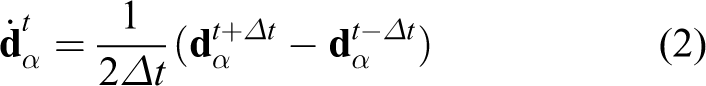
Based on the explicit central-difference time integration scheme, the velocity and acceleration of particle α can be approximated as

where

where
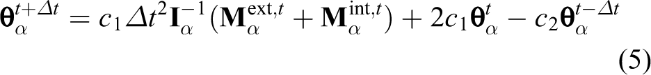
By iteratively solving equations (4) and (5), the translational and rotational displacements of particles at any time can be obtained. The particle displacement will further deduce the resultant forces of each particle at
In the “Three-dimensional beam element” and “Rigid-body element” sections, the three-dimensional beam element and rigid-body element based on the VFIFE method are introduced to model the struts and joints in locomotive tensegrity systems. Compared with previous model that treated the struts as axial force members and the joints as volumeless nodes, 19 the improved model using beam element and rigid-body element is able to mimic more details of the strut–tendon connections and the contact between the joints and ground.
Three-dimensional beam element
The solution of element internal force is only associated with the deformation of the element. The VFIFE method adopts virtual reverse motion, which deducts the influence of rigid-body displacement on the total deformation of the element, to obtain element pure deformation. Thus, it turns the problem of large deformation and rotation into a problem of small deformation and rotation. The pure translational deformation reflects the axial deformation of beam element while the pure rotational deformation reflects the deflection deformation of beam element. This article focuses on the motion behavior of locomotive tensegrity systems and therefore just briefly gives the derivation process and the resultant internal force of beam elements. More details can be found in the literature (Zheng et al. 27 ).
Three-dimensional beam elements will be used to model the struts in locomotive tensegrity systems. A three-dimensional beam element i that connects particles 1 and 2 is considered here to demonstrate the derivation of the beam internal force increment from time ta
to

(a) Positions and (b) displacements of beam element from time ta
to
By applying virtual reverse motion, the pure deformation of beam element can be derived from the element displacements.
27
There are six pure deformation components of element i during

Pure deformation of element 1–2.
Given the pure deformation, the beam internal force increments

where Ei
and Gi
are the Young’s modulus and shear modulus of material, respectively; Ai
is the cross-sectional area of beam element i;
The total forces and moments of the beam element are updated by adding the aforementioned increments. Note that coordinate transformation should be performed during this update.
It is worth noting that the above beam element can be easily simplified to cable element that only needs to consider axial elongations. Cable element will be used to mimic the tendons in locomotive tensegrity systems. For the sake of simplicity, the derivation of cable element is not presented here.
Rigid-body element
The tendon–strut connection usually has a fixed shape and size. In this study, rigid-body element is proposed to model the connection, as illustrated in Figure 3. The rigid-body element is represented by a particle A located at the mass center of the joint. The particle A owns 6 DOFs, where Rigid-body element.
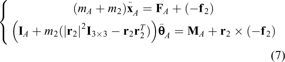
where mA
and
Computational model for locomotive tensegrities
Consider a locomotive tensegrity composed of n joints and nc members of which na members are active members. Figure 4 illustrates the computational model for a typical strut–tendon joint which connects a single strut and multiple tendons. The strut is modelled with a beam element, while the tendons are modelled with cable elements. The joint region is modelled with a rigid-body element to consider the joint size. At the rigid element, the particle of the beam element is taken as master particle A, while the particles of the cable elements are taken as slave particles 2. The motion of particle A follows equation (7). Therefore, the influence of the joint size is fully considered.

Schematic diagram of computational model for typical strut–tendon joint.
The motion of the locomotive tensegrity is controlled by actuating the active members. The control policy of the locomotive tensegrity can be described by an actuating function vector

where
The rest length

where
Besides, there are contact and collision between the tensegrity robot and the ground, which induces reaction and friction from the ground. A contact model based on the classic Coulomb law of friction
28
is adopted to consider the contact between the tensegrity joints and the ground. The contact force consists of a normal contact force vector

where
The self-weight of the locomotive tensegrity, including the weight of members, control module, communication module, and so on, are equivalent to external forces applied to the corresponding particles and expressed as

As a result, substituting the external forces and internal forces into equations (4) and (5), the motion of the tensegrity system can be determined by the explicit central-difference time integration scheme iteratively.
Validation by a six-strut locomotive tensegrity
Six-strut locomotive tensegrity
As shown in Figure 5(a), an ideal six-strut tensegrity system is composed of 24 tendons, 6 struts, and 12 joints. The outer surface of the six-strut tensegrity consists of 20 triangles, that is, 8 closed triangles (TCs) and 12 open triangles (TOs). The triangles can be identified by the nodes on their vertices and they are numbered in a way as given in Table 1 for the sake of simplicity. A physical prototype of a strut-actuated locomotive robot based on the six-strut tensegrity is manufactured, as shown in Figure 5(b). In the physical prototype, six servo linear actuators are used as active struts while 24 rubber ropes as tendons, and the actuators and rubber ropes are connected with 3D printed joints. Compared with the ideal system, the struts and the tendons of the physical prototype cannot strictly intersect at the centers of the strut ends. In the previous studies, 19,20 the detailed configuration of the joints is ignored and the struts and tendons are assumed to intersect at the ends of the struts. In this section, the prototype is re-modelled by using the proposed model to consider more details of the connections, as shown in Figure 5(c).

Six-strut spherical tensegrity: (a) configuration, (b) physical prototype, and (c) numerical model.
Number of triangles.

The properties of the actuated struts and the tendons of the physical prototype are given in Table 2. Since the strut is modelled as a 3D beam element, the second moment of area of the beam element is equivalently determined according to the cross-sectional size of the actuators and is also given in Table 2. As shown in Figure 6(a), 3D printed crown-shape joints are used to connect the tendons with the struts. The deformation of the joint during the motion of the system is very small and thus the joint is assumed as a rigid body. As shown in Figure 6(b), the rigid body used to model the 3D printed joint has the same shape as the real joint, and the locations where the tendons are connected are also the same as the locations at the real joint. The detailed information of the joint is given in Table 3.
Properties of members.


(a) 3D printed joint and (b) corresponding rigid-body model.
Model and simulation parameters.

The tendons of the system are modelled by cable elements as in the previous studies. 19,20 In the center of the prototype, a control box consisting of a Bluetooth communication module, a servo control module, and a lithium battery is attached to the joints with 24 rubber ropes the same as those used for tendons. The weight of the control box is 127.6 g, as listed in Table 3. The control box is also modelled as a rigid body and connected to the joints with 24 cable elements. Other actuating information and default values of parameters are listed in Table 3. It is worth mentioning that the Rayleigh damping coefficient is determined by an empirical formula 29 using the initial frequency of the tensegrity robot (4.53 Hz) and the mass damping ratio (0.05). It is also worth noting that the damping coefficient affects the dynamic responses of the tensegrity robot after actuating but has little influence on the success of rolling gaits, according to trial calculation.
Feasibility check of rolling gaits generated using previous model
The labels of the initial and final touching-ground triangles are used together to notate a rolling gait. Ten typical gaits obtained using the previous model 20 are given in Table 4. A recheck on the feasibility of these gaits are conducted with the proposed model and the results are also presented in Table 4. It shows that three gaits, that is, gaits No. 5, 6, and 10, which were deemed as feasible in the previous simulator are turned to be infeasible in the new simulator using the proposed model. To validate this founding, experiments on the physical prototype with the given gaits are conducted and the results are also listed in Table 4. It is found that the physical prototype cannot achieve rolling with the gait No. 9 besides the gaits No. 5, 6, and 10. It is obvious that the numerical prediction on the feasibility of the given rolling gaits has been improved from 60% to 85.71% by the proposed model.
Numerical and experimental results on feasibilities of typical rolling gaits.

Rolling gaits generated by improved model
Generating rolling gaits
A genetic algorithm (GA) incorporated with a DRM-based simulator using the ideal numerical tensegrity model has been proved to be effective in generating simulated rolling gaits. 30 Here a new gait generator is built by replacing the DRM-based simulator with the proposed VFIFE-based simulator that uses the improved tensegrity model. With the new generator, 40 new rolling gait primitives are found and the detailed control policies of them are given in Table 5. They are classified into two categories, that is, TC6→TO5 and TO5→TC6 according to the reference initial and final states of the locomotive tensegrity.
Rolling gait primitives generated by using improved model.

Experimental validation
If the initial state of the tensegrity is TC, it can roll to three adjacent TOs, which means that each primitive corresponds to 24 (=3 × 8) TC→TO gaits in the real world. Similarly, if the initial state of the tensegrity is TO, it can roll to two adjacent TCs and thus each primitive corresponds to 24 (=2 × 12) TO→TC gaits in the real world. Due to the symmetry of the tensegrity system, 31,32 for each primitive, if the initial state of the tensegrity system is given, the corresponding control policy can be obtained through affine transformation on the corresponding reference control policy given in Table 5.
Due to the unavoidable errors in material properties, geometry, mass distribution, and so on, of the physical prototype, there is a certain difference between the numerical model and the real system. As a result, a control policy that can drive the numerical tensegrity rolling may not work when applied to the physical prototype. To check this, all the 24 gaits corresponding to each primitive are experimented on the physical prototype. Experiments of typical gaits are shown in Figure 7. For each primitive, the number of corresponding gaits that successfully drive the physical prototype rolling is recorded. The success rate which is defined as the ratio of the number of successful gaits to the number of the tested gaits, that is, 24, is used to indicate the robustness of the primitive, and is shown in Figure 8(a). It is found that 14 primitives in Table 5 have a success rate of 100% which means that these primitives totally tolerate the difference between the numerical model and the physical prototype to some extent. For comparison, 40 gait primitives generated by the idealized tensegrity model are also tested in the same way. It is found that no gait primitive with a success rate of 100% was found in the comparative experiments of the gait primitives obtained from the idealized tensegrity model (Figure 8(b)). Those primitives with a success rate of 100% are good candidates as basic gaits which will be combined and repeatedly applied to achieve long-distance travel of the locomotive tensegrity. It is also found that 31 out of 40 primitives in Table 5 have a success rate above 80% which is again not achieved by any gait primitive generated by the idealized tensegrity model. Thirty-nine out of 40, that is, 97.50%, primitives in Table 5 have a success rate not lower than 50%. While for the gait primitives generated by the idealized tensegrity model, 13 out of 40, i.e. 32.50%, primitives have a success rate not lower than 50%. According to the statistical results illustrated in Figure 8(c), the distribution of success rates of the gait primitives generated by the improved simulator is more concentrated and the average is higher than those generated by the conventional simulator. The distributions of the two data groups are checked through the Kolmogorov–Smirnov normality test, and the p values are Experimental observation of typical rolling gaits corresponding to primitives Nos. 7 and 36. (a) Gait TC4→TO4 from primitive No. 7 with a result of feasible rolling. (b) Gait TC4→TO12 from primitive No. 7 with a result of infeasible rolling. (c) Gait TO7→TC6 from primitive No. 36 with a result of feasible rolling. (d) Gait TO7→TC8 from primitive No. 36 with a result of infeasible rolling. Experimental results of gait primitives generated by (a) improved simulator and (b) conventional simulator, and (c) statistical comparison of experimental success rates of the two simulators.

Conclusions
An improved numerical model considering the detailed configuration of the tendon–strut connection for locomotive tensegrity systems is proposed based on the VFIFE method. The classic six-strut locomotive tensegrity is taken as an example to verify the proposed model. It is found that the proposed model is able to get closer to the physical experiment prediction on the feasibility of given rolling gaits generated by the previous model. Meanwhile, the rolling gait primitives generated by the proposed model present much higher success rates than the rolling gait primitives generated by the previous model in the experiments with the physical prototype. It is believed that the proposed model significantly improves the accuracy of the motion simulation of locomotive tensegrities by considering the detailed configuration of the tendon–strut connection. It is also should be pointed out that there is still a non-ignorable difference between the simulations and the experiments due to the material error, geometry error, control error, friction coefficient error, and other sources of errors that cause the numerical system and environment to deviate from the physical prototype and the real-world environment. Refining the physical prototype and incorporating an experiment-based learning algorithm into the gait generator will further improve the success rate of the numerically generated gaits.
Footnotes
Declaration of conflicting interests
The author(s) declared no potential conflicts of interest with respect to the research, authorship, and/or publication of this article.
Funding
The author(s) disclosed receipt of the following financial support for the research, authorship, and/or publication of this article: This work was funded by the National Natural Science Foundation of China (Grant Nos. 52178175, 51908492, and 52238001) and Center for Balance Architecture, Zhejiang University.