
Abstract
Currently, research is being carried out on a new type of parallel robots, such as cable-driven parallel robot. The cable-driven parallel robot are parallel robots with flexible (cables), with a large workspace, with high speeds and accelerations of the end effector. In the cable-driven parallel robot, cables can only work in tension, and cable-driven parallel robot lose their performance when they are compressed. This feature severely limits the development and application of cable-driven parallel robots and requires further development of cable-driven parallel robot modeling on various software systems. Currently, Adams multibody dynamics software is widely used to create and test virtual prototypes of mechanical systems. But for cable-driven parallel robot modeling, the Adams program is quite complex and expensive to use. In this article, the simulation of the cable-driven parallel robot is carried out on the SimulationX software. Unlike other software packages, SimulationX is more accessible and cheaper and is well suited for cable-driven parallel robot simulation. Cable-driven parallel robot modeling on SimulationX allows you to identify the main design flaws even before its prototype is made. A model on the SimulationX software of a suspended cable-driven parallel robot with a point mass end effector, taking into account the elastic-dissipative properties of cables, was developed. The prototype of suspended cable-driven parallel robot with a point mass end effector was manufactured. Experimental researches of the prototype of the suspended cable-driven parallel robot with a point mass end effector confirmed the correctness of the application of the model on SimulationX for practical calculations.
Introduction
The cable-driven parallel robot (CDPR) is a special class of a parallel robot, in which the end effector (EE) is supported in parallel by m cables, which are driven by n actuators. The position and orientation of the EE of the CDPR is controlled by flexible cables, and not by rigid links, in contrast to conventional parallel robots. The CDPR have the advantages of conventional parallel robots and have a higher payload to weight ratio. The CDPR have lower inertial characteristics, which provides high speed and acceleration of the EE. Due to the flexibility of the cables, CDPR has the largest workspace among existing robots. The main disadvantage of the CDPR is that the cables can be driven by positive tension in order to keep the straight-line shape rather than negative compression. One of the first CDPR was Robocrane is shown in Figure 1, which was developed in 1989 in the USA by the National Institute of Standards and Technology (NIST). 1,2 CDPR Robocrane was intended for handling cargo in ports, during the construction of bridges, and so on. CDPR Robocrane is a Gough-Stuart platform suspended on six cables. Here, cables are used instead of hydraulic cylinders, and gravity is an implicit additional drive.

The CDPR Robocrane (NIST).
A typical CDPR consists of three parts, including a fixed frame, an EE, which is connected via m cables to the fixed frame. The length of the cables is changed by winches, which are driven by servomotors mounted on a fixed frame, as shown in Figure 2. 3,4

Scheme of a CDPR with m cables.
The CDPR with m—the number of cables and n—the degree of freedom (DOF) can be classified 5 as an under-constrained m < n + 1; a completely constrained m = n + 1; a redundantly constrained m > n + 1. In addition to the above classification, the CDPR are divided into two types—suspended and not suspended, depending on the location of the cables. If in a CDPR all drive cables are above the EE, and gravity acts as a virtual cable to maintain balance, then such the EE is called suspended. 1,6 –8 If in the CDPR at least one drive cable is below the EE, then such a CDPR is called not suspended. 9,10
In suspended CDPR, the cables are located above the EE, and the payload is distributed between the cables, so these CDPR have a large load capacity. A feature of suspended CDPR is the lower probability that the cables will collide with other environmental objects, due to the fact that all the cables are above the EE. The structure of the suspended CDPR is well suited for lifting and moving various loads. The disadvantages of suspended CDPR are the low rigidity in the vertical direction. Suspended CDPRs can get out of control under variable external forces, especially during the unloading operation.
Of particular interest are the suspended CDPR with a point-mass EE in which all cables are attached to a single point on the EE and can vary in length to control the position of the EE. 11,12 Typically, the EE is modeled as a concentrated mass located at the intersection point of the cables. Although in many cases the center of mass of the EE is not really located at the point of intersection of the cables, the distance of this displacement is considered small compared to the dimensions of the CDPR. The suspended CDPR with a point-mass EE is well suited for operations similar to those of construction cranes when lifting and moving loads. However, a suspended CDPR with a point-mass EE has significantly less payload fluctuation than a crane when performing the same operation due to its parallel design. The suspended CDPR with a point-mass EE for transporting and placing heavy objects on construction sites is developed in the work, 13 as shown in Figure 3.

The suspended CDPR with a point-mass EE for transporting.
In Figure 3, four cables are connected at one point, forming an EE, and an object is suspended at this point. The workspace is located between four columns. The rigidity of a CDPR in the horizontal plane is higher than that of an overhead crane, which is beneficial for precise positioning.
In this article, the suspended CDPR with a point-mass EE is modeled on the SimulationX software, taking into account the elastic-dissipative properties of cables. After the simulation, it is planned to make a prototype of the suspended CDPR with a point-mass EE and check its compliance with the developed model on the SimulationX software. The novelty of the article lies in the simulation of the CDPR on a simple and cheap SimulationX software to evaluate the parameters of the prototype of the CDPR before its will be made.
A suspended CDPR with a point-mass EE
Let us consider a suspended CDPR with a point-mass EE with 3-DOF and four drive cables, as shown in Figure 4. A feature of this CDPR configuration is that in order to maintain equilibrium, it is necessary to take into account gravity. In this configuration of the suspended CDPR, the EE is considered as a point-mass, which has only translational degrees of freedom. This assumption is correct since the dimensions of the EE are much smaller than the workspace of the CDPR. As can be seen from Figure 4, the suspended CDPR with a point-mass EE consists of a metal frame in the form of a rectangular parallelepiped 1, near the base of each vertical rack there are winch with servomotor 4 designed for winding (or unwinding) cables 2. The other ends of the cables 2 passing through the pulleys 5 are connected to the EE 3. The direction of rotation, as well as the speed of rotation of the winches with servomotors 4, is set by the control unit 6. Winches with servomotors 4 winding (or unwinding) cables 2 and change their length. When changing the lengths of the cables 2, the position of the EE 3 changes in the workspace of the CDPR, which is limited by the frame 1. In the design suspended CDPR with a point-mass EE, shown in Figure 4, the EE has three translational DOF.

The suspended CDPR with a point-mass EE.
Forward and inverse kinematics of a suspended CDPR with a point-mass EE
The kinematic scheme of the suspended CDPR with a point-mass EE (shown in Figure 4) is shown in Figure 5. The following designations for the dimensions of the fixed rectangular CDPR frame are introduced: a—width, b—length, h—height. The global coordinate system O(XYZ) is set in the middle of the rectangular base of the CDPR frame, and the EE has position coordinates
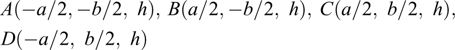
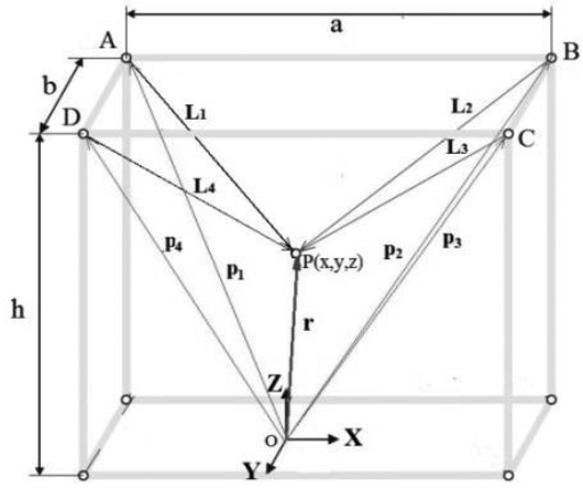
The kinematic scheme of the suspended CDPR with a point-mass EE.
The four cable support racks are of the same height and are placed in a rectangle on the ground, if deformation is not taken into account. To simplify the model, the cables are considered as a massless body without deformation, and it is assumed that the cables are straight and stretched.
In Figure 5, the following notations are introduced:
The coordinates of the vector
Coordinates of the vector

The equations for the inverse kinematic problem for the indicated kinematic scheme of the CDPR are presented as distances from the point P with the current coordinates x, y, z to the vertices of the quadrilateral A, B, C, D, we obtain from Figure 5. Applying the method of closed vector contours (shown in Figure 5) we obtain the following system of constraints

where the vector

The scalar cable length is determined by the formula

The unit vector

The unit vector

Next, from the system of four equations (5), you need to choose three of them and directly calculate the position of the EE. Let’s choose the equations related to the first, second and third cables, then from equation (5) we get the coordinates of the EE

where z has two solutions and, in accordance with the features of the workspace of the suspended CDPR with a point-mass EE, the solution with a negative sign is correct. It should be noted that in (5) the equation for determining the length of the fourth cable is not used. The position coordinates of the EE are determined using the first three equations of system (4).
Model of a suspended CDPR with a point-mass EE on SimulationX
Due to the fact that CDPR is a fairly new type of parallel robots with flexible links, the need for its modeling is an important task. CDPR simulation allows engineers to test and optimize designs before prototyping. Currently, CDPRs are often modeled using following software: MATLAB/Simulink, 14 MapleSim, 15 Dymola, 16 Gazebo simulator, 17 CoppeliaSim simulator, 18 CASPR-software for CDPR analysis and simulation, 19 WireX software for analysis and design of CDPR. 20
From the analysis of publications on the simulation of CDPR, the use of software for modeling the dynamics of multiple bodies MSC ADAMS has become widespread. 21 The work 22 carried out the simulation of the CDPR on the software for modeling the dynamics of multiple bodies MSC ADAMS. The EE and frame structure were modeled as rigid bodies. The cables were modeled as linear springs of low mass. However, the article does not show the CDPR model on MSC ADAMS, it does not explain how the model was compiled, only the simulation results are given. The work 23 shows the model Incompletely Restrained Cable-Suspended Swinging System (IRCSWs2) on MSC ADAMS. This article does not show the stages of compiling a CDPR model on MSC ADAMS, and it is not clear how the elastic-dissipative parameters of cables were taken into account in the simulation. In the work of Wang et al., 24 dynamic modeling of hoisting ropes was carried out using MSC ADAMS. The model is based on the assumption that there is no relative slip between the rope and the drum; the associated tensile and torsional stiffness are neglected; the rope is wound onto the drum exactly in a spiral. This model is well designed and shows all the steps of its compilation on MSC ADAMS, but it is not suitable for CDPR simulation. In the work of Rodriguez-Barroso et al., 25 the CDPR was simulated using the MSC ADAMS multibody dynamic software. This model takes into account the masses of the cables, the friction forces and the elasticity of the cables, but it does not show the stages of the simulation the winches and servomotors of the CDPR.
It can be seen from the analysis of works on the modeling of the CDPR on MSC ADAMS that in many works they refer to the applications of MSC ADAMS without a detailed description and compilation of models of the CDPR. Despite the fact that Adams is the most powerful and advanced software, the compilation of CDPR models is a time-consuming creative process. The use of MSC ADAMS is justified for the study of existing CDPR, with the aim of further research and optimization of its work. At the same time, at the stage of initial design of a CDPR, it is quite sufficient to use simple and cheap software for its simulation. We have analyzed software: MATLAB/Simulink, MapleSim, Dymola, Gazebo, CASPR, WireX, SimulationX. These programs are cheaper than Adams and they can be used to simulate CDPR at the initial design stage. In our work, for the simulation of CDPR, we use the SimulationX software. 26 Compared to Adams, MATLAB/Simulink, MapleSim, Dymola, Gazebo, CASPR, WireX, the SimulationX software is cheaper and more accessible to use. The reason for choosing SimulationX for CDPR simulation is the presence of an advanced Belt Library which contains: belt models, pulley and drum models, belt drives models and the authors have experience with the SimulationX program. 27
The SimulationX software allows you to build CDPR models from intuitive objects of mechanics: (mass, force, moment, spring, damper, friction, cable, etc.), pneumatics and hydraulics (pneumatic cylinder, valve, throttle, etc.), mechanical engineering and electro-mechanics (motors, clutches, gear, and other transmissions) and control (measuring sensors, control signals, etc.).
We research the dynamics of the CDPR is shown in Figure 4. On Figure 6(a) shows the model of suspended CDPR with a point-mass EE on the SimulationX software and on Figure 6(b) shows 3D-view of the CDPR SimulationX model to visualize the motions.

Simulation (a) the model of suspended CDPR with a point-mass EE on the SimulationX and (b) 3D view of the CDPR SimulationX model.
Elements of the SimulationX library, which were used in compiling the CDPR model, are shown in Figure 7(a).

(a) Elements of the SimulationX library, (b) discretization of the element Cable Spring.
List of symbols and description of elements of the SimulationX library (shown in Figure 7(a)): Sphere. This element models the EE in the form of a sphere. Here the mass, center of mass, and inertia tensor are modeled. Cable Preset (ideal Drum). This element models the CDPR winch as an ideal massless drum that can wind or unwind an endless cable. Pulley with Cable Section. The element models a round pulley with a cable contact section, for use in a three-dimensional cable drive. The pulley can be free (i.e. in a system of blocks and hoists) or attached to the frame. Cable Spring. The element is a free section or strand of cable for analysis of longitudinal vibrations of the cable. It has internal discreteness for masses and damper springs, as shown in Figure 7(b). The element calculates the stiffness and damping force acting on the line between points P
1 and P
2. The direction of the element is the line connecting P
1 and P
2. The mass of the cable does not affect the Cable Spring element, but is taken into account by the connected pulleys or drums. The element calculates the current stiffness ki
and damping bi
depending on the current length of the cable section lx

where EA is the axial stiffness of the cable, B is the damping coefficient of the cable.
5. Signal Block Function. The element is designed to calculate the function y = F(x)
The CDPR model on the SimulationX software allows you to explore the dynamics of the CDPR, taking into account the stiffness and damping of its cables, the masses of the pulleys, and the consideration of slip between cable and pulley. Cable length change equations are determined from the solution of the inverse kinematics problem (3) and are entered through the Signal Block Function elements connected to the Cable Preset elements to control the CDPR cable winches.
The following results are obtained from the CDPR model on the SimulationX: deformation, deformation velocity, normalized deformation of the cables; length of the unloaded cable section (incl. coiled lengths); cables tension, change of potential energy of cables; displacement, velocity, acceleration of EE.
Experimental setup
Prototype of a suspended CDPR with a point-mass EE
To assemble the prototype of suspended CDPR with a point-mass EE, the configuration of its system was developed. The configuration of system of the prototype of CDPR is shown in Figure 8. The following initial data are given: dimensions a = 1235 mm, b = 1500 mm, and h = 1690 mm. The mass of the EE m = 10.0 kg. Cables brand Dyneema, LIROS D-Pro 01505-0200, diameter 2 mm, cross-sectional area A = 3.14 mm2, mass per unit length p = 0.18 10−2 kg/m, specific cable stiffness k = 38,000 N, damping coefficient B = 20 Ns/m. 5 Pulley radii of winch drums R = 40 mm.

The configuration of system of the prototype of suspended CDPR with a point-mass EE.
The CDPR cable drive (shown in Figure 8) consists of four winches with drums mounted on a shaft with two bearings at both ends. The winches are coupled to four hybrid stepper motors Nema34—86HB250-156 B (shown in Table 2) with HBS86H drivers. The HBS86H drivers are connected to the Mach 3 hybrid stepper motor controller. The controller supports 4-axis control, interpolation algorithm with minimum error, high processing accuracy. Using the Mach 3 controller, the CDPR is controlled by a computer via a USB port. The tensions in the CDPR cables are determined using four tension sensor).
Technical parameters of the CDPR Hybrid stepper motor.

The tension sensors are connected to the ZET 058 strain gauge measuring system, 28 which, together with the ZETLAB TENZO software, allows collecting information from the strain gauges in real time via eight channels simultaneously. Strain gauge measurement system ZET 058 can be used for static and dynamic measurements of loads, deformations, torque, torsional oscillations, temperature and other physical values. Strain gauge measurement systems are represented by hardware and software suite based on multi-channel data acquisition system ZET 058 and ZETLAB TENZO software package. 28
According to the developed of the configuration of system of the prototype of suspended CDPR with a point-mass EE (shown in Figure 8), its prototype was made (shown in Figure 9).

Prototype of the suspended CDPR with a point-mass EE.
On Figure 10 shows the interface of program controlling the suspended CDPR with a point-mass EE.

Interface of the program for controlling the suspended CDPR with a point-mass EE.
According to the CDPR control interface, we can manually control the EE. You can make manual translational motions of the EE: forward-backward, left-right, up-down. In addition, it is possible to reproduce the trajectories of motions of the EE of a CDPR given by the curve equations, for example, a circle, an ellipse, etc. On Figure 11 shows the demo interface of the suspended CDPR with a point-mass EE circular trajectory of the EE at different times.

Demo interface of the suspended CDPR with a point-mass EE at different times (a) t = 2s, (b) t = 5s, (c) t = 8s, and (d) t = 10s.
The operation of the prototype of the suspended CDPR with a point-mass EE was tested on model on SimulationX, when the EE traced the trajectory of a circle with a radius of r = 0.2 m, the equation of which has the form

Based on the calculation of the CDPR model on SimulationX, the following results were obtained: on Figure 12(a, b) shows the graphs of changes in the lengths of the cables and their tensions, when the EE with a mass of 10 kg moves, according to the trajectory described by equation (7).
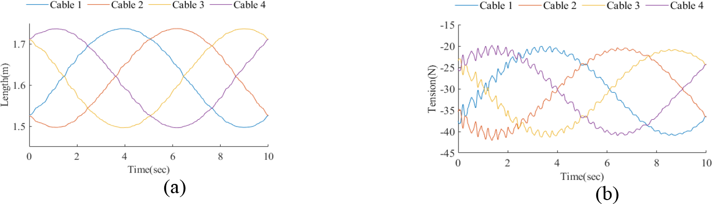
Simulated graphs: (a) changes in the lengths of the cables and (b) tensions in the cables.
From the calculation of the CDPR model on SimulationX, the following results were obtained: on Figure 13(a) and (b) shows the simulated graphs of the trajectory and velocity EE along the coordinate axes; on Figure 14(a) to (c) shows the errors of the EE trajectory along the coordinate axes, which arise due to the account of the elasticity of the CDPR cables in the simulation.

Simulated graphs of the trajectory (a) and velocity (b) EE.

The errors of the EE trajectory along the coordinate axes.
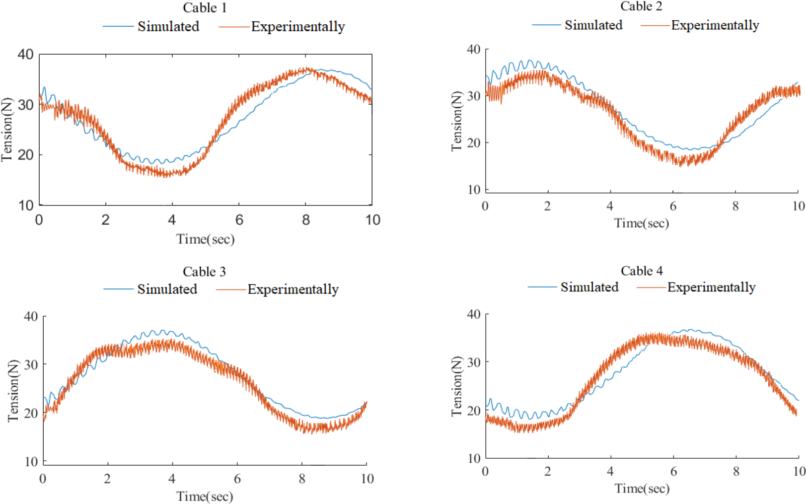
In the work, an experiment to determine the tension of the suspended CDPR with a point-mass EE cables, during the movement of its EE along a circular trajectory was carried out. On Figure 15 shows the graphs of cable tension calculated using the SimulationX model and measured experimentally.

Experimental and calculated graphs of the cable tensions.
From the analysis of the cable tension graphs (shown in Figure 15), it can be seen that there are significant deviations of the experimental values from the calculated values of the cable tensions.
These deviations are caused due to the sagging of the suspended CDPR with a point-mass EE cables during movement. To eliminate cable sagging, it is necessary to maintain a specified minimum cable tension throughout the entire cycle of its operation. We entered the data from the tension sensors into the control system. The signal about the level of cable tension from tension sensors is sent through the ADC (Load Cell Amplifier HX711) to the Mach 3 controller, which is connected to the computer via the USB port. The computer sets the value of the minimum tension in the cables, which will be maintained, taking into account the data obtained from the tension sensors, during its operation.
Figure 16 shows experimental and calculated graphs of the cable tensions with the control system maintaining the minimum cable tension.
Experimental and calculated graphs of the cable tensions with new control system.
Conclusions
This article presented the modeling of a CDPR at the stage of its initial design. From the analysis of the work on the modeling of the CDPR, it has been established that at the stage of the initial design of the CDPR, it is quite sufficient to use simple and cheap software for its simulation. The SimulationX software was chosen to simulate the CDPR. The main goal of CDPR modeling on SimulationX is to evaluate the parameters of the CDPR prototype at the initial stage of its design.
The following work has been done: A model on the SimulationX software package of a suspended CDPR with a point mass EE, taking into account the elastic-dissipative properties of cables has been developed. As a result of the calculation of the CDPR model on SimulationX, the graphs of the trajectory and velocity EE along the coordinate axes, the errors of the EE trajectory along the coordinate axes, arising due to the account of the elasticity of the cables, were determined. Experimental researches of the prototype of the suspended CDPR with a point mass EE have been carried out. The values of experimental tensions in cables are obtained. Experimental graphs of tension in the cables were obtained using tension sensors connected to the strain gauge measurement system ZET 058. A comparative analysis of the cable tension values obtained from the CDPR model on SimulationX with the experimental cable tension values was carried out. Experimental researches of the prototype of the suspended CDPR with a point mass EE confirmed the correctness of the application of the model CDPR on SimulationX for practical calculations.
In the future, the CDPR model on SimulationX will be finalized by including new elements of the SimulationX library, such as a servomotor, a winch and elements of a control system. It is planned to carry out experimental measurements of the position of the EE of a CDPR in order to improve its model.
Footnotes
Declaration of conflicting interests
The authors declared no potential conflict of interest with respect to the research, authorship, and/or publication of this article
Funding
The author(s) disclosed receipt of the following financial support for the research, authorship, and/or publication of this article: This research has been funded by the Science Committee of the Ministry of Education and Science of the Republic of Kazakhstan (Grant No. AP09259339).