
Abstract
Hexapod robots are widely used for resource exploration, post-disaster rescue, and military equipment. They typically travel on rugged and complex roads. The robot itself has a high probability of failure owing to mechanical failure, driving motor failure, or external environmental interference. To improve the adaptability of the robot to a complex environment, a motion control method for fault-tolerant gait was designed. The trajectory generator based on zero-moment point information can generate a smooth desired trajectory for the body’s center of mass, thereby improving the robot’s zero-moment point trajectory tracking effect and motion stability. The force-distribution algorithm based on torque optimization selects the minimum square sum of the driving force as the objective function and reduces the number of constraint equations through QR decomposition to increase the speed at which the expected contact force at the foot is calculated. A CoppeliaSim and MATLAB/Gurobi joint simulation platform were built to simulate and verify the fault-tolerant motion planning of the hexapod robot and foot contact force control algorithm. The feasibility and effectiveness of the fault-tolerant motion planning and foot force control algorithm applied to a hexapod robot with a single-foot failure are verified.
Introduction
Compared with wheeled robots, foot robots have more advantages in unstructured environments, including adaptability and flexibility in irregular terrains. 1 –3 Therefore, foot robots have wider application prospects in certain special environments. Niu et al. 4 proposed a novel rescue robot with a three-degrees-of-freedom leg mechanism based on the serial–parallel and wheel-legged mechanisms. However, a robot moving in a dangerous or disaster-hit environment is prone to leg failure and cannot be repaired manually. A robot with a foot fault is considered fault-tolerant if it can find a gait that will allow itself to continue to move in a particular environment. This will improve the applicability of foot robots in navigating unknown environments.
Presently, research on the fault tolerance of legged robots is focused on gait planning and execution. Mostafa et al. proposed a removable sliding-leg approach to solving this problem. A faulty leg can be detached, and other legs can slide to a better position by the command of the operator to obtain the optimum alternative gait configuration. 5 Asif et al. proposed a gait based on fault detection and diagnosis that can generate adaptive walking patterns with joint or sensor faults. 6 –8 Ding et al. specifically described several fault-tolerant gaits of a hexapod robot with one- and two-leg failures and carried out simulation and experimental verification on the NOROS. 9,10 Du proposed a method of motion planning through linear, fault-tolerant Jacobian matrices. 11 This method enables the robot to accomplish the desired movement using broken legs along with certain other concomitant motions as compensation.
Schleyer and Russell proposed an adaptive gait generation algorithm that is aimed at combining multiple failed legs. 12 By calculating the motion trajectories of the support and swing legs of a robot, stable linear motion can be obtained in any desired direction, and maximum walking stability can be ensured.
When walking, the hexapod robot with single-leg failure optimizes the actual irregular and unreasonable foot end contact force to solve the problems of internal force confrontation between the foot ends of the support phase and, ultimately, to maintain its body posture in a stable state. This results in excessive joint torque of individual legs, structural damage, excessive energy loss, and foot end slip. Various scholars have studied the optimization of the foot force of robots. Chen et al. 13 proposed a galloping gait control method based on a full-scale virtual model and optimal plantar force distribution. By transforming the force distribution calculated by the virtual model of the robot trunk into a quadratic optimization problem, the stability of the robot under flight trot gait can be improved. Valsecchi et al. 14 proposed a reaction motion strategy for a torque-controllable quadruped robot based on a sensing foot. The contact zero space was used to minimize the tangential force, minimizing the risk of slipping. Liu et al. 15 studied the relationship between the walking mode and foot force of an electric heavy hexapod robot in a three-legged gait. According to the structural characteristics of an electric heavy hexapod walking robot, a mathematical model of the normal foot force under a tripod gait in a typical walking mode was established. Biswal and Mohanty 16 calculated the optimal foot force of the joint torque of the quadrupedal robot, carried out dynamic modelling of the foot end and trunk of the quadruped robot, and realized the stability of the motion process through optimal foot force control.
In this study, we focused on improving the robustness and stability of a hexapod robot with single-leg failure. Based on previous research, we investigated fault-tolerant motion planning for a hexapod robot with a single-leg failure using a foot force control method.
The main contributions of this article are summarized as follows. Targeting the single-leg fault of a hexapod robot, the fault-tolerant triangular gait was designed and the gait parameters were determined. Compared with the fault-tolerant gait by Mostafa et al.,
5
this study optimized the initial angle of the joint based on the static stability margin (SSM) and designed an online trajectory generator based on predictive control. The trajectory generator based on zero-moment point (ZMP) information generated a smooth desired trajectory for the body centroid to improve the robot ZMP trajectory tracking effect and improve the motion stability. To further improve the motion stability of the robot, foot force control was added to the above control method. By decomposing the inertia force of the body mass center and compensating for the foot end position of each leg, the internal force between the feet caused by the tumbling moment of the body can be reduced. Based on the dynamic balance equation, friction constraints, driving force constraints, and touchdown constraints of the hexapod robot, the force distribution algorithm based on torque optimization selects the minimum sum of squares of the driving force as the objective function, reduces the number of constraint equations through QR decomposition to improve the calculation speed, and solves the expected contact force at the foot end.
The remainder of this article is organized as follows. In the second section, the kinematic and dynamic models are described. The third section describes the development of a fault-tolerant motion planning method. In the fourth section, a driving-force distribution method based on dual quadratic programming is proposed. The proposed method is verified in the fifth section through simulation experiments. The final section concludes the article.
Kinematics and dynamics modelling
The configuration of the hexapod robot used in this study is shown in Figure 1. The robot was composed of a body and six legs. The body has a hexagonal structure and six legs are distributed outside the body. Each leg had the same structure and three degrees of freedom. The heel joint is a rotating joint connecting the body and base joint, which is a primary pitching joint that connects the base joint with the thigh, and the knee joint is a secondary pitching joint that connects the thigh and lower leg. The heel, hip, and knee angles were α,

Structure of the hexapod robot.
Kinematic modelling
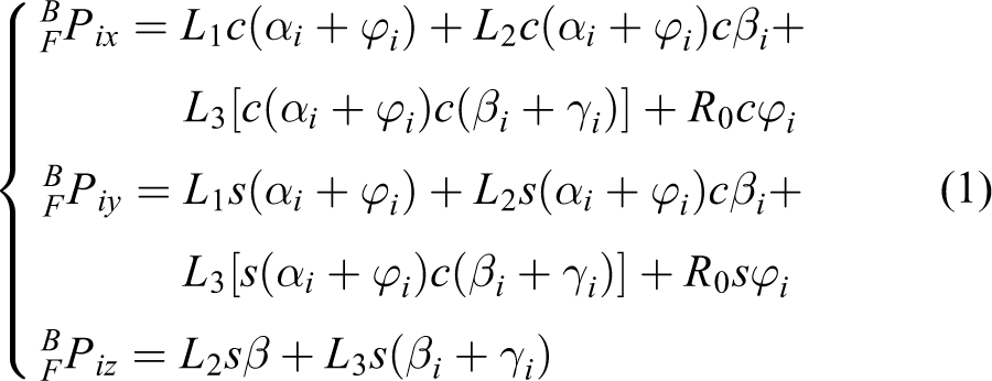
where c stands for
When the foot position vector and heel joint position are known, the single-leg inverse kinematic equation is as follows

where
According to the foot position information, the joint velocity


The foot position vector is
Dynamic modelling
The matrix form of the joint load torque generated by the leg i dynamics can be expressed as

The joint driving torque of hexapod robot i leg is

where
The hexapod robot was affected by gravity, friction, and inertial forces during motion. When a single robot leg fails, the actions of various forces affect the stability of the robot’s motion. The force condition of the hexapod robot during movement is shown in Figure 2. 17

Equivalent force of the hexapod robot in triangular gait.
A powerful balance formula was proposed to maintain the stability of the robot during motion

where FG
is the gravity of the real-time center of gravity of the body,
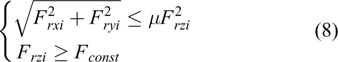
During movement, the gravity direction of the robot is always perpendicular to the ground; however, the real-time change in the position of the center of gravity will have a significant impact on the robot movement. Failure of the support leg of the robot leads to excessive force on the failed leg, foot slip, or rotational instability around the instability tipping sideline. Therefore, to prevent the robot foot from slipping, the following friction constraints must be satisfied
where
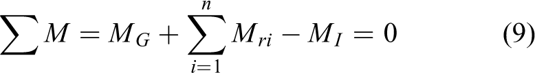
where MG
,
Fault tolerant motion planning method
Fault tolerant gait
When a hexapod robot moves in complex environments, such as when performing engineering exploration, disaster rescue, and extraterrestrial exploration, it faces mechanical, electrical, and control damage or failure owing to the interference and impact of the external environment, resulting in a lack of leg support and an inability to support its body.
In this study, we considered only the loss of one leg. The hexapod robot is isotropic in the direction of each leg; thus, to avoid repeated planning, we assumed that the leg failed and could not work. Thus, the robot lifted it as a load continuously; it was not considered in fault-tolerant gait planning. A five-step fault-tolerant triangular gait with a gait cycle in which three legs support the body and two swing legs was designed. 18 In the designed gait, each leg experiences two swing stages and three support stages. Therefore, the duty cycle of the fault-tolerant triangular gait is

In the fault-tolerant gait sequence diagram in Figure 3, the black line represents the support phase of the corresponding leg in the gait cycle and the direct blanks of the two black lines represent the swing phase. Evidently, the time lengths of the two support phases of the leg were different.

Phase sequence table of fault tolerant tripod gait.
The gait sequence in phases is as follows

Design of a predictive controller for fault-tolerant gait
When moving in outdoor terrain, the robot is affected by interference from external and inertial forces. These interference are exacerbated by complex ground fluctuations. In such scenarios, the classical SSM and other static stability determination methods that only use fuselage position information and centroid distribution to determine the stability of the robot are no longer applicable. The dynamic stability determination method can better solve the problem of determining the system stability of the robot in the process of motion, mainly because it can use the D’Alembert principle to equate the above disturbance to the centroid position and then analyze it.
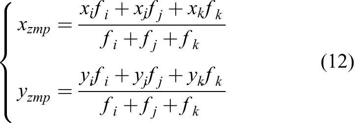
In summary, because the hexapod robot uses sensors to obtain the real-time foot force of the supporting foot, we used the ZMP method as the basis for judging the stability of the robot. Its advantage is that the disturbance can be equated to the centroid position using the D’Alembert principle, which is suitable for the stability analysis of a robot in complex terrain. The ZMP is the minimum value of the distance from the ZMP, which has zero moments in X and Y directions, on the plane to each side of the projection of the support polygon. As shown in Figure 4, let the coordinate of the ZMP be expressed as

Schematic diagram of ZMP. ZMP: zero-moment point.
The ZMP stability margin of the robot was the minimum distance from the ZMP to the support polygon.
In this study, the “table car” model was used to approximate the value of the ZMP
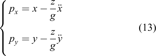
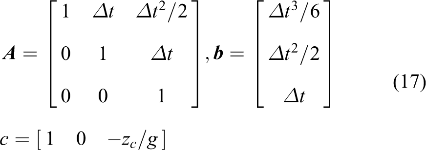
Applying modern control theory to the table car model, the differential of car acceleration versus time was defined as the system input variable. Therefore, equation (3) can be rewritten as the following system state equation 19

The continuous system equation (14) is discretized using time Δt

where

To make the output pk
of the system track the target
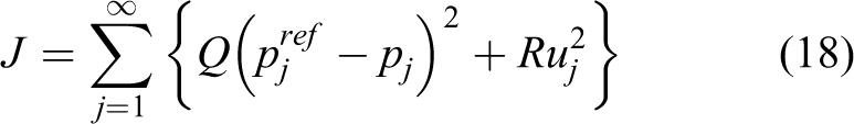
where Q and R are the positive weighting coefficients. According to the predictive control theory, this performance index can be minimized by using the input of the target reference value of the next N steps
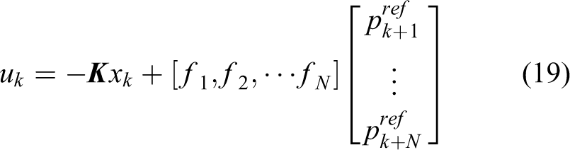
where


The preview controller consists of state feedback (the first term on the right), feed-forward of the inner product of the target reference value
A ZMP tracking deviation is observed when generating a long-distance walking mode using equation (19). To remedy this, equation (15) can be rewritten in the following extended form

The new input and state vectors are taken as

and

A controller was designed for the system defined by equation (22) to minimize the following performance indicators
The preview controller is given as follows


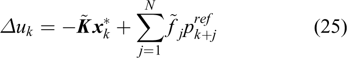
By using the above trajectory generator based on future ZMP information, a smooth desired trajectory can be generated for the body centroid to improve the robot’s ZMP trajectory tracking effect and motion stability. Based on the mechanical configuration, step height, gait cycle, and duty cycle of the hexapod robot, the expected ZMP trajectory in the future is designed to ensure that the expected ZMP has a sufficient dynamic stability margin. The discrete Riccati equation is solved using the dlqr function in the MATLAB control system toolbox to obtain the numerical solutions of P, K, and
In the predictive control theory, the associated control parameters are the hexapod robot body height zc
, acceleration due to gravity g, system sampling time
By multiplying both sides of equation (21) by

where
From equation (28) and the uniqueness of the solution of the Riccati equation, when
After g is determined, zc
and

Variation curve of the predictive gain.
Driving force distribution based on dual quadratic programming
First, the static balance equation of the hexapod robot system was established. The specific form of this equation is as follows

where


and I is the unit matrix.
The number of support legs of the hexapod robot is not less than three at any time; essentially,
In the process of foot ground contact of the hexapod robot, the foot end of the robot support leg must meet friction constraints to avoid relative sliding between the robot support leg and the ground. Because the size of the foot end can be regarded as a point relative to the body, point contact friction is assumed to exist between the robot’s foot end and ground
where
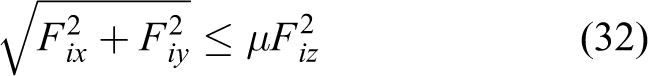
The optimization problem of the foot end contact force distribution of a hexapod robot is essentially a nonlinear programming problem, and finding its solution is a complex process. To improve the speed at which a solution to the optimization problem is determined, the foot end friction cone constraint is usually used instead of the inner pyramid constraint. As shown in Figure 6, the friction constraint was linearized. 21

Friction cone.
The inequality constraints shown in equation (32) can be replaced by the following

To ensure effective contact between the ground and support leg, the foot end contact force should satisfy the following constraints

Considering the limit driving force constraint, the following driving force constraints must be considered

where
From equations (32) to (35), all have the same mathematical representation; therefore, the above formula can be abstracted into a standard inequality constraint form with the same mathematical representation

The sum of squares of the joint driving forces is then selected as the objective function
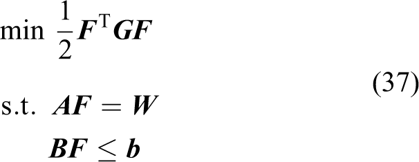
where

The quadratic programming problem with equality constraints is transformed into a problem with inequality constraints, which can reduce computational cost. The QR decomposition of
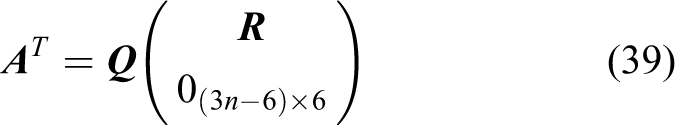
where

The dimensions of
Then,

where

Let

The optimal distribution of the driving torque of each support leg can then be obtained using equation (6). 22
Simulation verification
As shown in Figure 7, this study used CoppeliaSim and MATLAB to jointly build the simulation experiment platform, a shared memory plug-in to complete the communication between them and the Real-timePacer plug-in to synchronize the MATLAB numerical calculation time with the actual running time of CoppeliaSim. The simulation platform was divided into three parts. First, mechanical modelling of the hexapod robot was performed. The model was then imported into a simulation environment. Finally, a closed-loop joint simulation was conducted. The CPU model of the simulation platform was Intel(R) Pentium G4600. The parameter settings for the simulation are listed in Table 1.

Hexapod robot model. (a) 3D model and (b) joint hierarchy diagram.
Parameter setting for the simulation experiment.

The walking motion simulation experiment of the hexapod robot with a single-leg fault took leg 1 as the fault leg and used the remaining five legs for planning control. The total simulation time is 200s. The desired ZMP trajectory of the next gait cycle generates the desired position trajectory of the robot body through a trajectory generator based on predictive control. Because the simulation environment was an ideal flat terrain, and the motion speed set by the hexapod robot was low, the trajectory expected by the ZMP was designed as a continuous and smooth curve.
Figure 8 shows the position-tracking trajectory curve of the hexapod robot body with single-leg failure. The red solid line represents the feedback of the robot position sampled by the simulation system, and the blue dotted line represents the target position trajectory of the robot body. The position trajectory and target trajectory in each direction of the hexapod robot body were generated by the trajectory generator, and the target trajectory in the Z direction was determined by the height of the body. The tracking effect of the centroid position of the robot body was satisfactory in three directions of the world coordinate system. The control error in the X direction of the coordinate system was between −0.015 and 0.003 m, the control error in the Y direction was between −0.018 and 0.018 m, and the control error in the Z direction was between −0.05 and 0.05 m.

Body position tracking curve; (a) X-direction position tracking curve; (b) Y-direction position tracking curve; (c) Z-direction position tracking curve.
Figure 9 shows the attitude tracking trajectory curve of the hexapod robot body with single-leg failure. The dotted line represents the target attitude trajectory of the robot body, and the solid line represents the feedback of the robot attitude angle information sampled by the simulation system. The yaw, pitch, and roll angles of the robot’s desired position and attitude were 0. In the world coordinate system, the yaw angle deviation of the robot’s attitude was between −0.3° and 0.5°, the pitch angle deviation of the attitude was between −0.65° and 0.95°, and the roll angle deviation of the attitude was between −0.45° and 0.65°. It can be observed from the figure that the yaw angle tracking control effect of the robot is satisfactory, and the deviation is controlled within a small range. The yaw, pitch, and roll angles of the hexapod robot exhibited periodic changes. It can be observed from the figure that the hexapod robot with single-leg failure will not collapse or experience instability, and the yaw angle control effect of the hexapod robot with single-leg failure is satisfactory.

Body attitude tracking curve. (a) Yaw angle tracking curve; (b) pitch angle tracking curve; (c) roll angle tracking curve.
As shown in Figure 10, the foot end contact forces in the X, Y, and Z directions show periodic changes. Because the foot end contact forces in the X and Y directions are very small when the robot runs at a uniform speed on a horizontal plane, when feet 2, 4, and 5 switch from the swing phase to the support phase, with the forward movement of the center of gravity, the foot ground contact force of the legs gradually increases until the other swing legs share part of the gravity when they land. The legs are then lifted and enter the swing phase. It can be seen from the figure that when feet 2, 4, and 5 are in the support phase, the contact force at the foot end in the Z direction is not significantly different, and it does not exceed 1500 N.

Simulation results of the changes in the foot force. (a) Simulation results of the changes in the foot end force of foot 2; (b) simulation results of the changes in the foot end force of foot 4; (c) simulation results of the changes in the foot end force of foot 5.
The positional relationship between the foot end and the body center of gravity in the projection coordinate system can be obtained according to the coordinates and inertial navigation information of the foot end in the body coordinate system. With this information, the minimum value of the distance between the body’s center of gravity and each side of the leg support polygon during the movement of the hexapod robot with single-leg failure at any time can be determined.
In this study, the stability margin of fault-tolerant gait based on ZMP and foot strength optimization and typical fault-tolerant gait presented in Mostafa et al. are compared. According to Figure 11, the stability margin of the human body under the fault-tolerant gait based on ZMP and foot benefit optimization proposed in this paper was maintained between 517 mm and 935 mm and that of the robot under the classical fault-tolerant gait was maintained between 425 mm and 935 mm. Compared with traditional methods, the minimum stability margin of this method was increased by 21%; thus, the hexapod robot with single-leg failure has higher motion stability under the joint action of fault-tolerant gait planning and foot force optimization control of the ZMP hexapod robot.

Stability margin variation curve.
The simulation results reveal that the fault-tolerant motion planning online generation algorithm of the hexapod robot based on predictive control enables the hexapod robot with a single-leg failure to realize fast fault-tolerant walking on flat terrain. The actual ZMP trajectory has a good tracking effect on the target ZMP and ensures the dynamic stability of the robot during the motion process. Under the joint action of the predictive control and force optimization algorithm, the desired robot centroid trajectory generated by the trajectory generator based on the predictive control achieved a good tracking effect. Simultaneously, the stability margin of the robot significantly improved.
Conclusions
Considering the leg fault of the hexapod robot, a fault-tolerant triangular gait was designed, and the gait parameters were determined. An online trajectory generator based on predictive control was designed. The trajectory generator based on the ZMP information can generate a smooth desired trajectory for the body centroid to improve the robot ZMP trajectory tracking effect and improve the motion stability of the robot. Second, to improve the motion stability of the robot that considers the dynamic balance equation, friction, driving force, and touchdown constraint conditions of the hexapod robot, the force distribution algorithm based on torque optimization selects the minimum sum of squares of the driving force as the objective function and reduces the number of constraint equations through QR decomposition to reduce the speed at which the desired contact force at the foot end is calculated.
An online generation algorithm for fault-tolerant motion planning for a hexapod robot based on predictive control is proposed, which makes the hexapod robot with single-leg failure realize fast fault-tolerant walking on flat terrain. Furthermore, force distribution algorithm based on torque optimization is proposed. Finally, QR decomposition was used to improve the calculation speed of the algorithm and further improve the stability of fault-tolerant gait walking.
Footnotes
Declaration of conflicting interests
The author(s) declared no potential conflicts of interest with respect to the research, authorship, and/or publication of this article.
Funding
The author(s) disclosed the receipt of the following financial support for the research, authorship, and/or publication of this article: This work is funded by approach of Cooperative Perception, Decision, Control and Experimental Verification for Large-scale Hexapod Robots Traversing on Complex Environments (91948202) and research on Fault-tolerant Control Method and Switching Strategy of Heavy-duty Hexapod Robot with Lack of Full-state Motion Ability (52175012).