
Abstract
This article presents the design, functional simulation, and prototype of an innovative adaptive jaw gripper. First, based on the comparative analysis of several types of anthropomorphic finger grippers and adaptive jaw grippers, to avoid their disadvantages, the structural scheme of a gripper module based on a polycontour mechanism, comprising a guided parallelogram contour, was established to obtain a parallel translational movement of the elements of the jaw holders and therefore of the jaws. Then the structural analysis is briefly made to verify the correct operation of the mechanism of the gripping module, and details of the kinematic analysis and of the design of the components in the CATIA software are given. After obtaining the 3D version of the gripping module, its functional simulation and ADAMS analysis is performed. The sensory system used at the level of the jaws is also described and then the gripper assembly is obtained including a base plate and five gripper modules and as a result an adaptive gripper with five jaw holder elements is created. Next is the functional simulation of the adaptive gripper for gripping several types of parts. The prototype made and the test are presented for gripping five types of parts and we show the prospects of continuing this research with practical applicability by mounting on a robot and implementing in a robotic line for gripping and handling a series of parts of various shapes and sizes.
Keywords
Introduction
Mechanical jaw grippers are made in many variants, some of which are widely used today. The main disadvantage of these grippers is the limited scope: for gripping a single part type or a part whose size varies between close limits. For gripping parts whose shape is different with relatively small variations in size, anthropomorphic (finger) grippers were designed and made, similar to the human hand, including in size, which are still expensive, with low reliability and therefore are not available for common applications.
Thus, an anthropomorphic structure (Shadow project—England) with 21 degrees of mobility (each finger has 4 degrees of mobility, and the thumb has 5 degrees of mobility) 1 is well-known. Another version made by Dainichi Company, Ltd. Kani, Japan, has 20 couples and 16 degrees of mobility (3 on the fingers and 4 on the thumb) and a weight of 1.4 kg. 2 The version offered by the French firm Techno Concept can be with 3, 4, or 5 fingers. 3 Dist Hand has four fingers, each operated by 6 polyester tendons, actuated by 5 DC motors, and the fingers are equipped with position sensors and touch sensors. 4 DRL Hand has four fingers with three degrees of mobility and one additional degree of freedom in the palm. 5 Barrett Hand has three fingers and three degrees of freedom and continuous reconfigurability. 6 Another recent example of a five-finger anthropomorphic gripper is described in Kim et al., 7 but it has a high complexity and a considerable price, which does not make it accessible for current industrial applications. Under these conditions, it is more efficient to design a gripper adapted to a series of concrete robotic applications. As a solution of this kind for the gripping of parts with various shapes and relatively large variations in size, adaptive grippers were made. In addition, adaptive gripping systems are able to take into account the particularities of the gripped part (shape and weight) and make decisions to achieve a secure grip. Examples of such prehensors are three cases: Robotiq 2 Finger Apdaptive, 8 with a single contact area on each jaw holder, with the gripped object, the SamPlIng gripper, 9 which has two contact areas with the pre-gripped object on the jaw holders and the Cassino 1 gripper 10 and the Cassino2-LARM Hand gripper, 11 which has a higher degree of adaptation to the pre-gripped part type.
Another example of a three-jaw adaptive gripper that can be replaced with three fingers is described in Backus and Dollar. 12
This gripper is characterized by the possibility of two fingers to adapt to the direction of the surface to grip by self-orientation, but it can grip small parts without guaranteeing the maintenance of the initial orientation of the gripped part.
The paper 13 describes a gripper, with three to six fingers with the possibility of some of them changing their orientation toward the base, which can grip small parts, especially by encompassing.
The paper 14 describes a locally adaptable two-finger gripper, specialized for gripping and handling, including the installation of electronic cables. Here is the precise destination of the use of this gripper.
Another somewhat adaptive gripper with the possibility of gripping the parts at predetermined points is described in Wan et al. 15
Following the comparative analysis of several types of grippers, in particular with jaws, including those presented of the adaptive type, taking into account the data contained in 16 –18 as a result, however, jaw grippers have a limited area of use, including current adaptive ones, anthropomorphic grippers, including those described, are still expensive and relatively low in reliability and the concrete problem to be solved, namely the gripping of a set of flat parts with various configurations, from the automotive industry, without changing the initial position, the objective was to achieve a new type of gripper that could safely grip parts of various shapes and with significant differences in size, with five independently operated jaw holders, of identical mechanisms, in which the jaws are, in a first stage, equipped with sliding sensors. The novelty of this gripper consists in the safe gripping, with five jaws with independent movements, a set of parts with various configurations, without changing the initial position. Another innovative and original aspect is that the jaws have rectilinear movements and remain parallel to themselves due to the use of a parallelogram mechanism guided by a translation coupling for their operation. These innovations make this gripper have a much larger area of use than grippers with conventional jaws, be much cheaper and more reliable than many anthropomorphic grippers, and have greater adaptability than adaptive grippers known because it has a modular construction with low cost, each component gripper module has an independent movement (the gripper has a degree of mobility five) and is equipped with an advanced sensory system. This article presents the main stages of designing this type of gripper, CAD simulation of operation, analysis under the action of forces in ADAMS, the prototype made and its testing. The gripper will solve a concrete problem on a robotic production line for gripping and transferring parts of complex shapes with significant variations in size specific to automotive components in the structure of engines, gearboxes, car transmissions, and so on.
The main stages of the gripper design
Establishing the structural scheme
It was decided that the gripper should have five jaw holders corresponding to five gripper modules to generate five points (limited areas) of contact between the jaws and the gripper so that the grip is secure regardless of the external shape of the gripped part. The structure of the gripping modules is identical, hence the modular character of the gripper, and the low manufacturing cost, each gripping module being practically a monomobile mechanism actuated by an electric motor. As a result, the degree of mobility of the gripper is M = 5. 19 Imposed by the area where the gripper is to work, but also as a solution for optimizing the grip, the jaws will have a translational–rectilinear movement, remaining parallel to themselves. To obtain this movement, a CFGD parallelogram mechanism was used, with HE guiding rods (two guiding rods for a higher precision of movement and an optimal distribution of forces that require the elements of the gripping module mechanism, according to the schematic diagram in Figure 1).

Schematic diagram of a gripping module.
For the contour 0-1-2-4-0(0- the fixed element) results the degree of mobility
Kinematic features
The kinematic scheme I (Figure 2(a)) and the kinematic scheme II (Figure 2(b)) are used for the kinematic calculation. Following the kinematic calculation, by applying the closed vector contour method, in the contour ABCDG′A and then in the contour DEFF′D ′D, in the Dxyz reference system, we will obtain the position of the point F, so the value of the distance d6, depending on the angle of rotation

Schemes for kinematic calculations (a) contour 0-1-2-4-0; (b) contour 0-4-5-6-0.
According to Figure 2(a), it results

Further from the scalar system:


we have d1 = d1(a
0), and d2 = l4(l4 = CE)-d1, so d2 = d2(
According to Figure 2(b), it results
Further from the scalar system


we have
Functional simulation in CATIA software
The Sketcher Module is used. It is the module where the geometric description of the desired part is created in the plan, and the geometric shapes of the parts can be specified or not.
Part Design mode is still used only after the part has been dimensioned and described in the Sketcher module, after which we enter Part Design mode and 3D modeling is performed. In the creation of the 3D model of a part, many details related to its processing and assembly are taken into account.
With the Assembly Design module, all parts are inserted after they have been created to make the gripping module. The parts will be mounted according to the degree of freedom necessary to achieve the needed movement of the gripping module without simulating it. Initially, the fixed parts are put in position and it is declared that they are fixed, and the next parts will be moved after the fixed ones.
After completing the stages of 3D modeling and observing the kinematic conditions, the gripping module was made. Figure 3 shows compliance with the kinematic scheme and the 3D mechanical structure, so that the kinematic couples have the necessary degrees of freedom. The couples (A), (B), (C), (E), (F), and (H) are of the bearing type between the parts forming the lever arms and the radial-axial bearings, to reduce the frictions in the movement of the gripping module. The translational movements are performed with the help of linear ball guideways (D) and (G), which allow a very good continuity in the movement of the gripping module. With the help of bearings and guideways, we get very low friction in couples, which helps us in 3D simulation because the simulation is ideal and therefore friction is neglected. 22 The semi-constructive variant (Figure 3(b)) is obtained, according to the kinematic variant (Figure 3(a)), after which the functional simulation shown in Figure 4 is performed.

Representation of the constructive scheme (b) corresponding to the kinematic scheme (a).

Stages of kinematic simulation of the gripping module.
To perform the kinematic simulation in the CATIA program, we must enter the DMU Kinematics mode, where the implementation of constraints and couples are required. As in the kinematic diagram, in CATIA, there is a primary couple and the rest are secondary couples. The primary couple exerts the movement, and the secondary ones follow it until it stops or is in a moment of mechanical limitation. Figure 4 shows the kinematic simulation stages of the gripping module. 22
Generative structural analysis
This type of analysis is done to structurally analyze the deformations of bodies or assemblies when a force is applied. This analysis is done in the Generative Structural Analysis module which is used to check the structure and reliability over time of the mechanical components and to identify the stressed areas. By identifying the stressed areas, we can establish the implementation areas of the sensors. The stressed areas (Figure 5) are represented in red, and the least stressed in blue, the gripping module being subjected to a force of 5 N on closing and opening too. 23

Generative structural analysis of the gripping module.
Study of the gripping module with ADAMS software
Import of the gripping module into Adams
After obtaining the outline in a design program such as CATIA, the components are imported into Adams, or depending on the Adams version, the entire gripping module can be imported directly. Once the gripping module is imported, the type of material for each part is declared to apply the constraints. The first constraint is the fixing of fixed objects, followed by the constraint of the following parts. 24 With the help of these tools, all the components of the gripping module were constrained (Figure 6), to be able to achieve its movement. Along with these constraints, it must be declared which of the constrained couples is the primary one, and then the secondary ones must be declared.

Representation of couples in Adams.
Performing the simulation in Adams
After all the couples have been applied, and the forces necessary for the movement have been applied to the components of the gripping module, one of these forces is constant, namely the gravitational force. Fulfilling all the functionality conditions, the 3D simulation of the gripping module can be applied.
After determining the time and steps required to generate the complete movement of the gripping module, we start and the gripping module will move to the forward position from the origin, as shown in Figure 7. 25

Simulation of kinematics in Adams.
Graphic simulation in the Adams program
Following the simulation in the Adams program, an acceleration sensor was applied to the entire module. This simulation was performed by applying the driving force of the 2 Nm of the gripping module, to which was added the gravitational acceleration 9.8 m/s2.
The graph in Figure 8 shows the maximum stress values on a complete cycle performed by the module (advance-retract). These efforts are amplified over time as mechanical wear occurs in the couples and bearings or mechanical clearings may occur and they may create vibrations in the system.

Maximum values of stress on a complete cycle performed by the module (advance-retraction) in ADAMS.
Friction forces are not taken into account in the simulation, which means that the system is considered to perform ideal movements. 25
The friction forces that can occur in the system and are not taken into account are multiple and these are the friction forces in the bearings, the friction forces between the components, the friction forces of the system due to non-compliance with the dimensions. These forces will be taken into account in a future stage of constructive and functional optimization of the gripping module.
Due to the parallelogram-type mechanical structure driven by a rotational motion, it has a slight retraction acceleration and a slight advance deceleration.
Graphic highlighting in CATIA of the effort according to the angular position
With the help of the graphs, we can see the stress values of each couple depending on the angular position they have. In a gripping module, there are six rotation couples in which the JOINT function is applied to generate a rotational motion. For the most stressed couple exemplified in red, we have the graph represented in Figure 9.
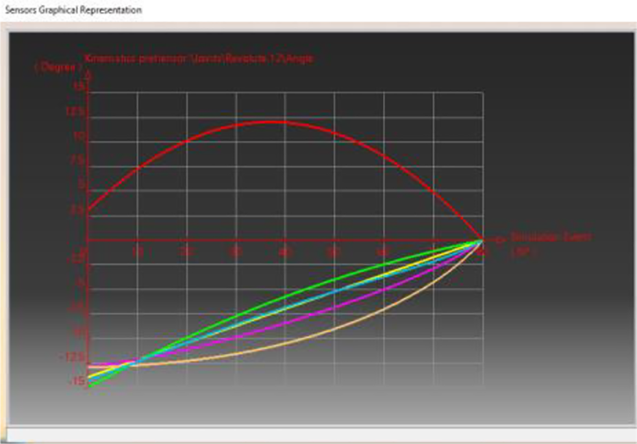
Graph of the most stressed couple.
In this gripping module, a single couple makes a positive movement, and the others are influenced by it by making a rotating movement in the opposite direction. The graph in Figure 10 shows in green a couple that makes a negative rotational motion.
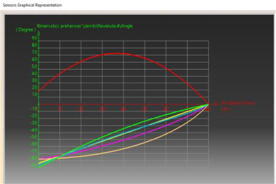
Graph of a rotating couple with negative motion.
Optimizing the shape of mechanical components
For the analysis and optimization of mechanical components, the following steps were followed: selection of the components with the highest wear; application of parallel and perpendicular forces to the advance and to the retraction on the chosen mechanical components; 3D performance of deformations by the finite element method; generation of deformation parameters and calculation error and geometric modification of components according to results. 26
Selection of the components with the highest wear
The gripping module is actuated by a stepper type electric motor that generates a couple of 8.2 kg × cm, which means that it exerts a moment on the 0.911 Nm components. Figure 11 shows two images: the first image represents the front view of an adaptive gripping module where the mechanical components that have greater wear over time by their rotational movement are represented in red; the second image is a 2D representation of the gripping module in which the couples are represented (a red line at points A, B, C, D, E), where the components and their numbering can be mechanically locked. The mechanical component 1 is locked in the couple A, the mechanical component 2 is locked in the couple B, the mechanical component 3 is locked in the couple C, and the mechanical component 4 is locked in the couple D, respectively, the couple E depending on the forward or retraction movement.

Representation of rotation couples and choice of components with the highest wear.
Applying forces on mechanical components that perform a horizontal translational movement
The example of optimizing the shape of the mechanical components is made for the part with translational movement with the help of ball bushes (linear guideways). With their help, the gripping module performs its translational movements easily because they take over some frictions of the system. Over time, this system that performs the movement through guideways can be blocked or braking phenomena can occur due to lubrication or impurities accumulated between the balls. When the linear guideways are blocked, the force exerted on the system is distributed in the mechanical components. Figure 12 shows a force composition diagram where the force is applied at a chosen position of 30° to the horizontal plane to simulate the distribution of the force in the translation system.

Composition of translation system forces.
The force (F) is applied to the mechanical component (3) which performs a translational movement with respect to the mechanical components (1) and (2). At the moment of locking, the force is evenly distributed in the two rods, and they in turn transmit the force on the component 4 where they are embedded. After the moment of locking, the force (F) tends to move in the direction of the normal force (Fn) because the component (3) is locked and does not perform any movement. Once the distributed force reaches the direction of the normal force, the system tends to be deformed downwards (Figure 13).

Stages of deformation of the translation system.
To find the values for the resistance of forces Fx, Fy, Fz, Mx, My, and Mz, the finite element method was applied to the system, after which a force ratio was generated (Figure 14) and the values are listed in Table 1.

The ratio of the resistance forces in the mechanical translation system.
Value for the resistance of the forces generated on the system.

Mechanical construction of a gripping module
For the mechanical design of a gripping module, a precision in the dimension chain generated by each component is necessary. One of the main causes of mechanical blockage is improper machining of the components. Each mechanical component can in turn generate errors, and in a system where rotational and translational movements are performed at the same time, these errors block or slow down the system. 27 The most convenient mechanical solutions were chosen for all mechanical components from rod-type elements to rotating elements, ball bearings or radial bearings or translation elements. Regarding the jaws used, the jaw fastening system must be fast to be reliable and cost-effective. In general, jaws that are intended to grip objects have a rough surface or are flattened (have scratches on the contact surface) for the best possible contact with the object. In the adaptive grip system, the jaws are made of a softer material because it is also intended for gripping objects with sensitive surfaces, and they must not leave marks on the object. This can be seen in Figure 15.

Adaptive gripper jaw.
The final 3D project
To make the adaptive gripper, 5 gripper modules mounted on the central support rod are required. These modules are mounted on 5 sides milled in the shape of a pentagon and are mechanically embedded there to prevent them from moving during movement or vibration. The gripper modules are fixed to the rod (1), fixed to the lower plate (2) by means of a clearing-free, cylindrical wedge assembly (4) and a countersunk head screw (3), fixed inside the actuator enclosure (Figure 16).

Central system of the adaptive gripper.
Following the implementation of the gripper modules, the gripper in Figure 17 was made, where the marked plates (2, 5) are the support plates of the central rod and of the modules.
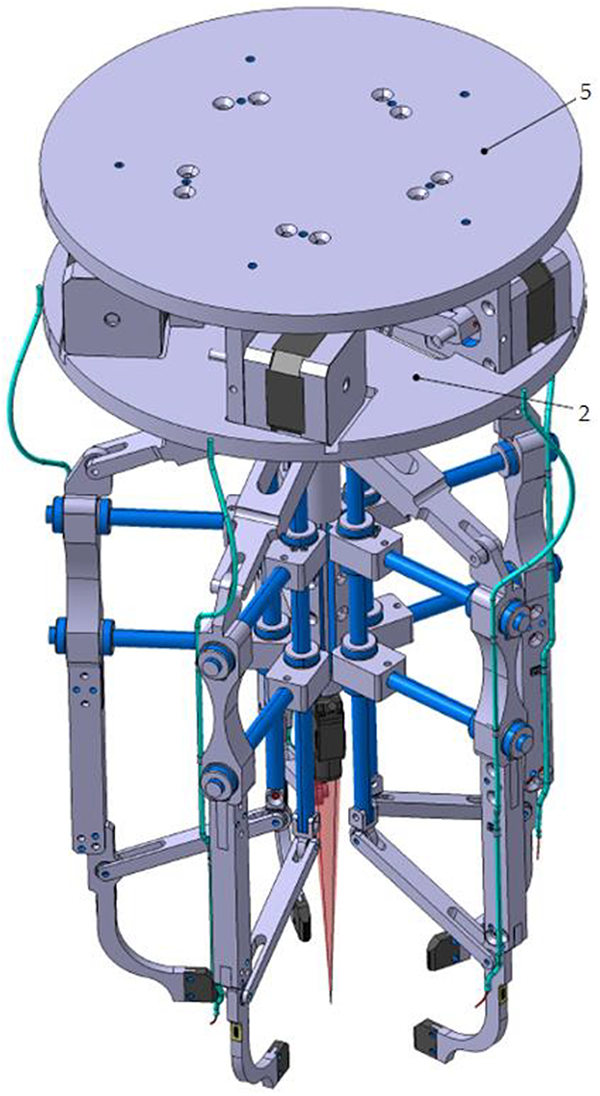
3D model of the self-adaptive gripper.
Components or areas marked in blue are areas made with lower tolerances to ensure the accuracy of the movements, and the video camera that will be mounted at a later stage is sketched in the central area.
Simulation of 3D model self-adaptive gripper operation
This gripper is self-adaptive due to its mechanical, electrical, and software features. The three features perfectly describe a mechatronic system that works simultaneously for each arm. Each gripping module performs its own tasks and in turn generates information related to its state. The following are examples of functional simulation for the capture of several types of objects. Most jaw holders have the ability to grip regular objects as shown in Figure 18. As can be seen, the object is held evenly by all jaws and in the same position. Once the jaws have touched the object, the drive system remains locked in that position. To check the adaptability, the gripper was implemented in the Kinematics Simulation module of the Catia program. The fixed part was declared, after which the states of the other parts were declared according to the fixed one. The type of couple and the direction of their movements were also stated. In a gripping module, there is only one active couple from where we generate motion throughout the system, and the rest of the couples are passive and are influenced by the first kinematic couple.

Adaptability of the gripper to an object with a regular shape.
Following the simulation in Kinematics Simulation, the table in Figure 19 was generated with the values of the active couples of each gripping module.
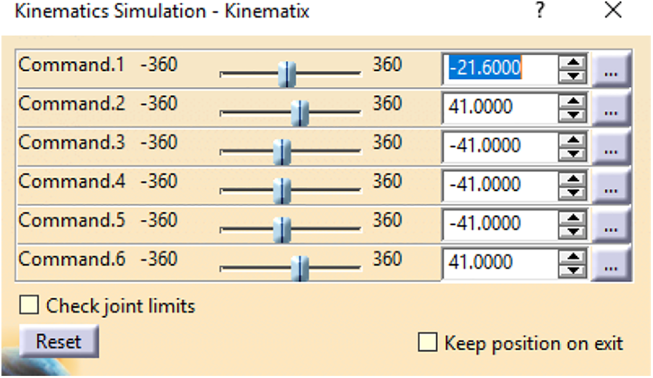
Table of couple values made in Kinematics. 23
The first value −21.6000, marked in blue, represents a rotational movement of the entire gripper. As can be seen in the table, all the gripper modules have the same angular value of 41°, which shows that the shape is regular and the independent movements of the gripper modules are identical.
To demonstrate the adaptability, simulations were also performed on objects with an irregular shape, where the independent movements of each gripping module are observed (Figure 20).

Adaptability of the gripper for an object with an irregular shape with straight sides.
Following the simulation in Kinematics, the angular differences of each gripping module during the gripping are observed. Different angular values show that the shape of the object is irregular (Figure 21).

Table of couple values made in Kinematics. 23
To verify the adaptability of the gripper, a simulation was also performed on an object with an irregular shape with curved sides (Figure 22).

Adaptability of the gripper for an object with an irregular shape with curved sides.
Prototype of the self-adaptive gripper
Based on the execution drawings of the mechanical components of the gripper, they were made physically, after which the gripper unit was assembled, the electrical connections were made to power the motors, obtaining the prototype of the self-adaptive gripper represented in Figure 23. For proper operation, they have made the necessary adjustments so that the operation of the kinematic couples is as good as possible. The gripper was mounted on the arm of a robot in Cartesian coordinates and will be tested for concrete grip operations.

Self-adaptive grip prototype.
Vibration testing of gripper modules
The quality of the gripping process depends on the safety of maintaining the gripped body during the robotized operation. An important cause that can endanger the quality of the grip is the level of vibrations in the grip system during the movement of the mobile elements of the gripper and the gripping action itself. The vibrations are generated by the mobile elements of the gripper and their amplitude is even greater as the number of mobile components simultaneously is higher but also depends a lot on the drive solution. In this case, during the operation tests, a high vibration level was noted and therefore it was necessary to measure the vibration level on each gripping module. For this, it was decided to use the vibration sensor type SW-18010P vibration sensor, 28 which was placed at the end of the jaw holder element, at point A, at a distance of 177.23 mm from the nearest fixed element, according to Figure 24, and which can measure the vibrations along the three axes: x, y, and z of the reference system attached to the sensor.
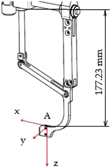
Location of the vibration sensor on the base member of the gripping module.
For the measurement of the vibrations of each gripping module, advance and retraction movements were induced on them over a distance of 102 mm. After capturing the information transmitted by the sensors, the corresponding graphics were generated. Figure 25 shows the graphs for gripper modules 1 and 2.

Graphical representation of the vibration amplitude measured by the vibration sensor for gripper modules 1 and 2 (a) amplitude of the vibration 2D-the gripping module 1; (b) amplitude of the vibration 3D- the gripping module 1; (c) amplitude of the vibration 2D-the gripping module 2; (d) amplitude of the vibration 3D-the gripping module 2.
Thus, for the gripping module 1, following the measurements in the graph in Figure 25(a) is represented the amplitude of the vibrations on a displacement of 102 mm as a function of time, and in Figure 25(b), the same amplitude is represented in 3D. According to the data, it is observed that the movement of the arm generates high vibrations, exceeding the nominal values (0–1000), so that the maximum value in point 131 reaches the value of 413593 in the x direction, followed by point 155 with the value 375741 in the y direction (the measure unit for the amplitude of vibrations is nm, and the high values are explained by the shocks that appear especially at the beginning and end of the stroke).
Figure 25(c) shows the vibration amplitude under the same conditions for gripper module 2, and Figure 25(d) shows the same amplitude in 3D.
According to the data obtained, it is observed that the movement of arm 2 generates high vibrations, exceeding the nominal values (0–1000), so that the maximum value in point 11 reaches the value of 611430 in the y direction, followed by point 108 with the value 385782 in the x direction and point 8 with the value 77293 in the z direction.
Similar data were obtained for the other three gripping modules. The high level of vibrations required the reanalysis of the constructive solution which led to the conclusion that the main cause of the vibrations and their high level is the direct actuation of the mechanism of the gripping module by the stepper motor. It has been observed that by rotating the motor shaft step by step, in this case by 1.6°, the system cannot control the shutdown of a gripping module nor can it brake when the end-of-stroke contact is detected, which generates shocks in the steering system so vibrations. As a result, it was proposed to replace the direct actuation of the gripping module mechanism with the actuation by a reducer to be interposed between the stepper motor and the gripping module mechanism, according to Figure 26. The introduction of the reducer has the advantage of smoothing the movement of the gripping module acceleration, start-up and braking required by the approach and contact of the gripped object. The step of the motor, this time set to 1.8°, is at the output of the reducer of 0.09º, which obviously leads to the uniformity and increase of the precision of the movement of each gripping module.

Actuating the gripping mode of a stepper motor through a reducer.
Following this modification, on the modified prototype, by measuring the vibration level, a significant reduction of them was found, as it results from the example given in Figure 27, for the gripping module 1 (representation of the amplitude in plan, Figure 27(a) and in 3D, Figure 27(b)). Thus, for a displacement of 177 mm, according to the data it is observed that the displacement of the arm generates small–medium vibrations, exceeding the nominal values (0–1000), but the maximum value in point 119 reaches the value of 46415 in the x direction, followed by point 40 with the value 25623 in the y direction and the point 112 with the value 19343 in the z direction, significantly lower than in the case of the first actuation solution. Similar values of vibration amplitudes were obtained for the other gripping modules.

Graphical representation of the vibration amplitude measured by the vibration sensor for the gripping module 1 in case of actuation with a reducer (a) amplitude of the vibration 2D-the gripping module 1; (b) amplitude of the vibration 3D-the gripping module 1.
The sensory system
The sensory system is based on the principle of detecting slip by rotating around an axis of an adherent system that comes into direct contact with the gripped object (Figure 28). 29 The component which comes into direct contact with the pre-gripped object is a flat band (5) which has an adherent surface in the contact area to ensure the transmission of motion. The flat band is taken out of the jaws to make contact with the object by sliding the component (3), making a movement of sliding translation through component (4). The contact movement with the object is detected by the translational movement of the flat band. Through this system, the gripper also measures the distance to the gripping jaw from the moment of contact with the object. 26 The sensory system detects the slip and presence of the object by transforming the R-T-R (rotational motion into translational motion and from translational to rotational). This exchange of generated types of movements amplifies the sensitivity of the movement. 29 After the gripping movement is performed, the jaws come in contact with the object and it can be moved. If it slides against the jaws, the flat band, from the translation movement it initially makes, performs a rotational movement with the whole translation system, moving at the same time the component (1). Component (1) is the part that ensures the return to position 0 of the sliding sensor by means of the extension spring (2).

Sliding sensor mounted in the jaw structure.
Prototype final version
Following the modification of the actuation system and the implementation of the above sensory system at the level of each jaw, the 3D model of the gripper represented in Figure 29 and the prototype of the gripper in Figure 30 were obtained.

3D model of the gripper in the final version.

Prototype of the gripper in the final version.
The 3D model shows a motor that can rotate the entire gripper, which was necessary for the fact that initially the gripper will be mounted on a Cartesian robot, in three axes, and this rotational movement is necessary to orient the part after gripping in the required final position.
Prototype testing in the final version
To test the prototype, a set of car parts was used, for the grip and handling of which this grip was designed and made. The set of parts is shown in Figure 31.

Parts used to test the gripper made (a) polygonal part type 1; (b) U-shaped part; (c) polygonal part type 2; (d) polygonal part type 3; (e) lever part.
The pieces are delimited in height by parallel planes, usually, and the lateral shape is polygonal or whatever. The grip must be made by contacting the parts considering the thickness, the side, without changing the initial position, which can be done with the five jaws operated independently of a gripping module, jaws that have rectilinear movements and remain parallel to each other.
Figure 32(a) to (e) shows the images with the gripper testing for pre-gripping the above parts in the side view and bottom view to see the relative arrangement of the jaws relative to the side surface of the pieces, the grip being safe and accurate.

Prototype testing for pre-gripping five types of parts. (a) gripping test polygonal part type 1; (b) gripping test Utype part; (c) gripping test polygonal part type 2; (d) gripping test polygonal part type 3; (e) gripping test of the lever-type part.
Regarding the tests presented in Figure 32, it can also be mentioned that typical parts that are part of assemblies and subassemblies in the automotive industry were selected; the aim was to perform tests to capture the actual situations of robotized assembly in that the parts were taken from a support similar to a storage box, in which such parts are usually stored; after gripping the parts were moved to another location at speeds similar to those to be used in actual assembly operations to verify the safety of the gripping; the parts were released in positions and on supports similar to those that will be involved in the real operations; the aim was to use working speeds to ensure high productivity and safety of the grip, so that the part is not accidentally dropped from the gripping system. The results obtained from the tests validated the last constructive solution of the gripping system presented.
Future directions of development
The gripper mounted on a robot will be implemented in a robotic line for gripping and handling parts of various shapes and sizes, such as those used in tests, which are part of several automotive subassemblies. To improve the operation and increase the adaptability of the gripper, it is considered to mount a video camera on its central axis for a prior identification of the part to be preheated and to preconfigure the gripper, to shorten the gripping time.
Conclusions
Based on what is presented in this article, the following conclusions can be drawn: – Adaptive mechanical grippers with jaws for certain special situations are viable alternatives to anthropomorphic finger grippers, still very expensive and sometimes unreliable. – Currently, it is possible to design and make grippers with jaws, including the adaptive type, with several jaw holders equipped with sensors at low costs, but with high functionality and adaptability. – Functional simulation of the 3D model and analysis in ADAMS are necessary to verify the correct operation and constructive optimization. – A prototype made must be tested in various situations to demonstrate proper operation and the ability to be implemented in a real robotic application. – Such grippers pave the way for large-scale robotization of assembly activities to subassemblies and complex assemblies in the automotive industry, but not only.
Footnotes
Declaration of conflicting interests
The author(s) declared no potential conflicts of interest with respect to the research, authorship, and/or publication of this article.
Funding
The author(s) received no financial support for the research, authorship, and/or publication of this article.