
Abstract
Recently, the increasing interest in underwater exploration motivates the development of aquatic unmanned vehicles. To execute hazardous tasks in an unknown or even hostile environment, researchers have directed on developing biomimetic robots inspired by the extraordinary maneuverability, cruising speed, and propulsion efficiency of fish. Nevertheless, the performance of current prototypes still has gaps compared with that of real fishes. In this review, recent approaches in structure designs, actuators, and sensors are presented. In addition, the theoretical methods for modeling the robotic fishes are consolidated, and the control strategies are offered. Finally, the current challenges are summarized, and possible future directions are deeply discussed. It is expected that the emergence of new engineering and biological technologies will enhance the field of robotic fish for further advancement.
Introduction
Under the thousands of years of natural selection, the fishes in nature have been endowed with great locomotion capabilities, such as high swimming speed and remarkable maneuverability, prompting researchers to develop various types of fish-inspired underwater robots. 1 Compared with conventional underwater vehicles powered by screw propellors, robotic fish can overcome their shortcomings, such as large scale, low energy efficiency, and disturbance to the environment, and it has great superiority in propulsive efficiency, maneuverability, and stealth. 2,3 With the development of mechatronic technologies and computer science, robotic fish plays a huge role in underwater exploration, 4 –6 samplings, 7,8 rescues, 9 and water quality monitoring. 10
The earliest research on fish can be traced back to 1926; Breder 11 categorized the swimming modes of fishes into the body and/or caudal fin (BCF) propulsion and median and/or paired fin (MPF) propulsion according to the body part utilized for propulsion. In 1936, through the observation of dolphins, Gary 12 calculated that dolphins need only one-seventh of the external force generated by their muscles to maintain a high swimming speed. This finding motivated researchers to study the mechanism of fish swimming. In the 1960s, some progress had been made in the theoretical study of fish propulsion. The theories could be categorized into resistive force theory 13 and reactive force theory. 14 –18 The former emphasizes the viscous force, while the latter emphasizes the more accurate inertia force. There are three kinds of reactive force theories that are relatively wildly used in fish dynamic modeling: elongated body theory (EBT), 14,18 wave plate theory (WPT), 15,16 and actuator-disc theory. 17 In 1995, based on previous studies, the first complete robotic fish system named RoboTuna 19 was developed by Massachusetts Institute of Technology (MIT). Since then, many related studies have been carried out, and the latest research results have been applied to the design of robotic fish. 20 Various types of fish-like robots have sprung up endlessly. 21 –24
To meet the increasing requirements of underwater missions, new approaches have been constantly proposed in design aspects. Recent advances in smart materials and actuators and compliant mechanisms have boosted the research studies on the mechanical design of robotic fishes. 25 Many smart control strategies are applied to improve the robotic performance, and closed-loop control based on onboard sensors is used to realize the precise control. 26 These approaches have been reviewed in recent articles, 26 –31 but few of them give an overall description. Salazar et al. 27 reviewed the modeling, materials, and actuators, but there is no mention of sensors and control. Xie et al. 31 reviewed the robotic fishes with different mechanisms in detail, but the control strategy is not deeply discussed. Yu et al. 26 offered a detailed review of control strategies, but the other aspects are not declared. Differently, this article focuses on the recent studies and gives a relatively overall review. The motivation is to provide a relevant and useful introduction to the state-of-the-art robotic fish and to inspire researchers to explore the opportunities for further improvement and novel designs in robotic fish from existing studies.
The remainder of this article is organized as follows: The movement characteristics of different types of fishes are summarized, and recent typical designs are given in the second section. Smart soft actuators with properties and limitations for propulsion are detailed in the third section. The applications of sensors in robotic fish are provided in the fourth section. Typical modeling and control methods are proposed, and related theoretical research studies are sorted out in the fifth section. In addition, possible future challenges and directions are discussed in the sixth section. Finally, conclusions are given in the seventh section.
Robotic fish designs based on different locomotion modes
As stated in the previous section, the swimming modes of fish can be categorized into BCF propulsion and MPF propulsion. The BCF mode is suitable for long-term swimming using the caudal fin to produce large thrust, whereas the MPF mode uses paired pectoral fins, dorsal fins, or anal fins to obtain sufficient maneuverability. As shown in Figure 1, 32 based on the difference between undulatory and oscillatory motion, BCF mode could be further classified into anguilliform, subcarangiform, carangiform, thunniform, and ostraciiform. MPF mode could be further classified into rajiform, diodontiform, labriform, amiiform, gymnotiform, balistiform, and tetraodontiform. Typical prototypes based on each category (as presented in Tables 1 and 2) are deeply discussed in this section.

Classification of swimming modes: (a) BCF and (b) MPF. Blue areas contribute to swim. Adapted and redrawn from Ref. 32 BCF: body and/or caudal fin; MPF: median and/or paired fin.
Performance and characteristics of the BCF mode-based robotic fishes.

BCF: body and/or caudal fin; MAR: marine anguilliform robot.
Performance and characteristics of the MPF mode-based robotic fishes.
MPF: median and/or paired fin.
BCF mode-based robotic fishes
Swimming in anguilliform mode is based on axial waves propagating along the body from head to tail, and the wave number is about one body length. 49 Hyper-redundant design is usually used in robots inspired by anguilliform to obtain high maneuverability. Envirobot developed by Bayat et al. 33 is composed of six active modules, a passive flexible tail, and an un-actuated head module (see Figure 2(b)). Struebig et al. 34 developed a new anguilliform swimming robot—named Marine Anguilliform Robot (MAR) (see Figure 2(a)). Different from hyper-redundant mechanisms, the core component of the robot is a helix. Several rectangular elements are adopted to project the three-dimensional rotation of the helix onto the vertical plane, and thus, a continuous traveling wave can be created. Since the robot is actuated by a single DC motor installed on the head, the efficiency of the robot is improved, and the control strategy is significantly simplified. However, the overall scale is relatively large (108 cm, 5.5 cm, and 25 cm in length, width, and height, respectively), and waterproof measures of each element are lacking, which leads to a larger friction force in swimming.

Robotic fish prototypes based on different BCF modes:(a) MAR. Reproduced with permission. 34 Copyright 2019, IOP Publishing. (b) Envirobot. Reproduced with permission. 33 Copyright 2021, IEEE. (c) Isplash-II. Reproduced with permission. 35 Copyright 2014, IEEE. (d) Compliant robot. Reproduced with permission. 36 Copyright 2017, IEEE. (e) SPC-III. Reproduced with permission. 5 Copyright 2011, Wiley. (f) Robot by Algarin-Pinto. Reproduced with permission. 37 Copyright 2021, MDPI. (g) Robot by Zhang. Reproduced with permission. 39 Copyright 2018, IEEE. (h) Robot by Costa. Reproduced with permission. 38 Copyright 2014, Springer. BCF: body and/or caudal fin; MAR: marine anguilliform robot.
In contrast to anguilliform that the whole body participating in undulation, the undulations in subcarangiform and carangiform are confined to the posterior half and the latter third of body length, respectively, while the nonundulating parts of both remain almost rigid. 50 As a result, the swimming speed is higher than that of the anguilliform while the maneuverability is lower. 51 Multi-joint mechanism is usually utilized to fit the movement of the counterpart fish. 52 –54 The iSplash-II developed by Clapham et al. 35 is well known for its high speed (up to 11.6 body length (BL) per second at the frequency of 20 Hz) (see Figure 2(c)). However, it can only realize linear locomotion but can not maneuver in 3D space. Zhong et al. 36 developed a novel robotic fish (see Figure 2(d)) with wire-driven active body and compliant tail, which were driven, respectively, by two servo motors housed in the head. The active body consists of five joints, and it could be bent in a C-shape and the soft compliant tail lags behind, resulting in an S-shape of the robot.
The fish swimming in thunniform mode has a crescent-shaped caudal fin with a high aspect ratio connected to a narrow peduncle. 12 Significant transverse movement occurs in the peduncle, and the tail area when swimming while the anterior body remains rigid, 55 which leads to high speed with high efficiency. Since only the rear 10% of the body participates in oscillation, the torpedo-shaped SPC-III developed by Liang et al. 5 uses a parallel four-bar linkage mechanism actuated by two DC servomotors to oscillate the caudal fin (see Figure 2(e)). Under the lookup-table method control and predictive control, the swimming speed can reach 1.36 m/s with a turning radius of 1.75 m, and the robotic fish can be operated for up to 20 h powered by the onboard battery. Pinto et al. 37 adopted the three degrees of freedom spherical three universal–cylindrical–universal and one spherical joint (3UCU-1 S) parallel mechanism as the actuation system of robotic fish (see Figure 2(f)). The 3UCU-1 S is driven by linear actuators to mimic the flapping thunniform locomotion, which obtains a high and efficient thrust.
The ostraciiform locomotion is considered the most stable mode as the body parts involved in oscillation is the least. Given to large body shape and inefficient fin actuation, the speed of ostraciiform is relatively low but they can maneuver in a narrow space (almost zero radius 56 ) through the fin actuation. 57 Recently, Costa et al. 38 have proposed an ostraciiform robot composed of a cylindrical rigid body and a tail section (see Figure 2(h)). The actuation system is based on a cam-like mechanism powered by a DC brushed motor, which converts the continuous rotation of the drive into a harmonic oscillation. Zhang et al. 39 presented a robot with a 2-segment caudal (see Figure 2(g)). The robot has a large and heavy main body to gain stability, and the caudal fin is actuated by an electromagnetic actuator to obtain higher frequency oscillations (over 50 Hz).
MPF mode-based robotic fishes
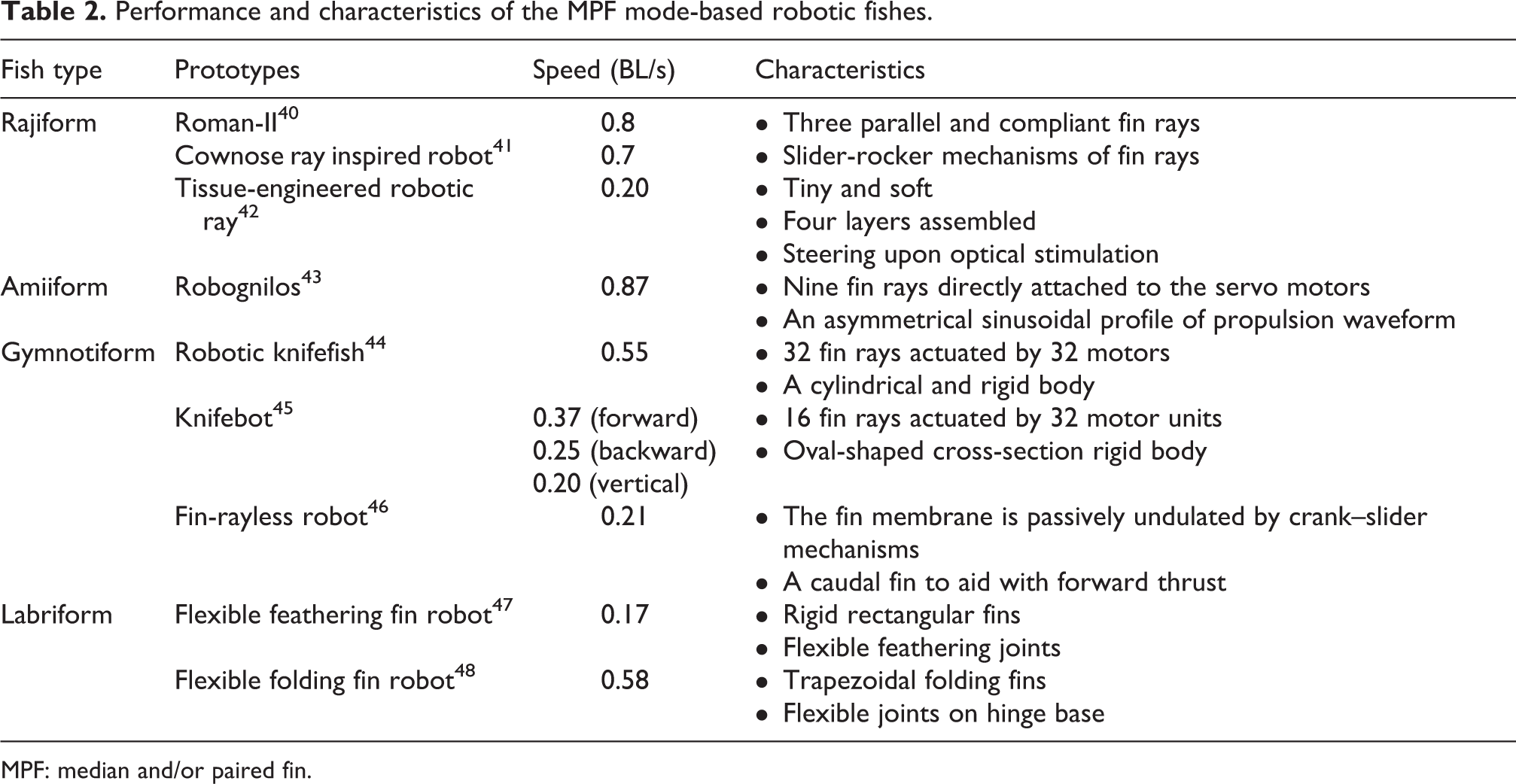
Rajiform has a pair of wing-shaped pectoral fins attached to the fin rays extended from the body. Swimming forward and turning are, respectively, realized by flapping and modulating phase relations of fin rays, exhibiting relatively high maneuverability and stability. 32 To achieve the rajiform locomotion, the actuation mechanism of the RoMan-II 40 consists of three parallel and compliant fin rays connected to each side of the body, as shown in Figure 3(a). The fin rays are powered by the brushless servo motors independently. Hence, the fin membrane attached to them could provide flapping motion. Differently, the fin rays of the robot developed by Cai et al. 41 are not compliant but adopt slider-rocker mechanism to flap in sinusoidal curves (see Figure 3(b)). Specifically, the front fin ray uses a one-stage slide-rocker mechanism, the middle fin ray uses a two-stage slider-rocker mechanism, and the last fin ray uses one linkage. Park et al. 42 developed a soft-robotic ray with a new design (see Figure 3(c)). The body of the robot is assembled by four layers including a three-dimensional elastomer layer, a chemically neutral skeleton layer, a thin interstitial elastomer layer, and a muscle layer of aligned rat cardiomyocytes. The robot is 16.3 mm in length and about 10.18 mg in weight, which is considered to be the smallest rajiform-inspired prototype. Upon optical stimulation, the metal skeleton induces the bending of the muscle layer to produce undulating locomotion. Consequently, the robot exhibits high maneuverability (turn at 1.5 mm/s), relatively high speed (3.2 mm/s, equal to 0.20 BL/s), and long endurance (6 days).

Robotic fish prototypes based on different MPF modes:(a) Roman-II. Reproduced with permission. 40 Copyright 2012, IEEE. (b) Cownose ray inspired robot. Reproduced with permission. 41 Copyright 2019, IEEE. (c) Tissue-engineered robotic ray. Reproduced with permission. 42 Copyright 2016, Amer Assoc Advancement Science. (d) Knifebot. Reproduced with permission. 45 Copyright 2018, IOP publishing. (e) Robotic knifefish. Reproduced with permission. 44 Copyright 2011, Royal Soc. (f) Fin-rayless robot. Reproduced with permission. 46 Copyright 2012, IEEE. (g) Flexible feathering fin robot. Reproduced with permission. 47 Copyright 2016, IOP publishing. (h) Flexible folding fin robot. Reproduced with permission. 48 Copyright 2020, Cambridge Univ Press. (i) Robognilos. Reproduced with permission. 43 Copyright 2009, Pergamon-Elsevier Science. MPF: median and/or paired fin.
Amiiform and gymnotiform have similarities in kinematics. Amiiform has a long dorsal fin extending to the entire body length, while gymnotiform has an elongated anal fin. They undulate their fins to swim while their bodies remain rigid. They could smoothly change the gait of swimming forward to backward without turning. 58,59 Furthermore, they could move vertically by sending inward counter-propagating waves, namely, the traveling wave from head to tail meets the traveling wave from tail to head in the middle of the fin. 44 Thus, they could maneuver in 3D space easily by controlling the unique long fins. Hu et al. 43 developed an amiiform-inspired robot. As shown in Figure 3(i), nine fin rays connecting with a membrane are directly attached to nine servo motors, and the motors are mounted in the long base. As for the gymnotiform, Curet et al. 44 used 32 fin rays actuated by 32 motors to emulate the dorsal fin. The bionic fin is encased in the cylindrical main body (see Figure 3(e)). Liu et al. 45 used 16 fin rays independently actuated by motor units (see Figure 3(d)). The fin rays are about 7 cm in length, longer than that of Curet et al.’ s 3.4 cm. The robot developed by Liu et al. 46 adopted the actuation mechanism using no fin rays (see Figure 3(f)). The fin membrane is passively undulated by two crank-slider mechanisms located at the head and the tail, respectively. Moreover, a propulsive caudal fin is also equipped to aid with forward thrust.
Labriform oscillates pectoral fins to generate swimming thrust and occasionally uses caudal fin for rapid acceleration. The movement of pectoral fins is a combination of rowing (vertical rotating axis) and flapping (longitudinal rotating axis) motion to perform slow-speed agile swimming. 60 Rowing motion including power and recovery strokes is utilized for forward swimming while the flapping for descending or ascending. 60 The fin mechanism put forward by Behbahani et al. 47 is about rowing motion. It can be seen in Figure 3(g) that the rigid rectangular fins are mounted on flexible joints driven by servo motors. The main components of the joint are a mechanical stopper and a rectangular flexible piece. During the power stroke, the mechanical stopper prevents the fin from feathering (transverse rotating axis) and maintains the rowing motion prescribed by the servo motors. In addition, in recovery stroke, the flexible piece makes the fin feather passively, thus reducing the hydrodynamic drag force. Pham et al. 48 proposed a different fin mechanism in the shape of a trapezoid (less interference drag than a rectangle) (see Figure 3(h)). The pectoral fins are mounted to the hinge base (fin ray) in the middle of the trapezoidal fins through flexible joints. Under this arrangement, the power and recovery strokes can be realized in the form of folding pectoral fins.
However, in diodontiform mode (undulatory pectoral fins), balistiform mode (undulatory anal and dorsal fins), and tetraodontiform mode (oscillatory dorsal and anal fins), there are no robotic systems reported to the authors’ knowledge.
Smart soft actuators for propulsion
The traditional motor-driven robotic fish systems are composed of multi-joint body and transmission mechanisms, such as gears, bearings, and pistons, which makes the robots heavy and bulky. In addition, the motors could generate noises and disturb marine life, incapable of integrating into the underwater ecology. 4 Conversely, the emergence of artificial muscle-based actuators provides a new direction for the development of robotic fish. Although their power and accuracy cannot be compared with motors, smart soft actuators have unique advantages in terms of high deformability and adaptability due to their excellent compliance. 61 Moreover, they could be used as a part of the robot to propel without additional mechanisms. Typical smart soft actuators, such as shape memory alloy (SMA), electroactive polymer (EAP), piezoelectric actuators (PZT), and fluid elastomer actuator (FEA), are reported in robotic fish design, which is discussed in this section. The characteristics of the mainly used smart soft actuators in robotic fish are presented in Table 3.
The characteristics of the mainly used smart soft actuators in robotic fish.

SMA: shape memory alloy; IPMC: ionic polymer-metal composite; PPy: polypyrrole; DE: dielectric elastomer; PZT: piezoelectric actuators; FEA: fluid elastomer actuator.
SMA-based robotic fishes
The principle of SMA is the shape memory effect, namely, the low-temperature martensite reverses into the high-temperature parent phase when heated and returns to the pre-deformation shape during subsequent cooling through the release of internal elastic energy. 67 SMA can be actuated under a small applied voltage (about 2 V) and generates a high output stress (up to 200 MPa). 62 SMA is suitable for underwater robots because the surrounding water is a benefit to cooling down the SMA, and faster frequency could be obtained. 68 SMAs in the form of wire, spring, and plate are found in robotic fish design. Li et al. 69 attached two SMA wires in the form of a trapezoid (to double the stress) of different lengths to each side of an elastic substrate (the backbone of the fishtail) to achieve both undulatory and oscillatory motions (see Figure 4(a)). Coral et al. 70 adopted 19 ribs and a rigid caudal fin to form the fish body instead of a compliant one. Two groups of SMA wires actuate the fish body and the tail, respectively (see Figure 4(b)).

SMA-based robotic fishes: (a) Actuation structure bending to side A and side B, SMA_A1 and SMA_B1 are longer than SMA_A2 and SMA_B2 to undulatory and oscillatory movement. 69 Copyright 2019, IEEE. (b) A robotic fish based on SMA wires. The dashed line represents the SMA wires, the red line represents the spine, and three types of swimming modes are realized. Reproduced with permission. 70 Copyright 2018, IOP publishing. (c) The SMAs pass the holes to drive the segments. Reproduced with permission. 71 Copyright 2008, IEEE. (d) Red areas represent deforming regions. Reproduced with permission. 72 Copyright 2019, Springer. (e) Gestures of a robotic pectoral fin based on observations. (i) relaxation; (ii) expansion; (iii) bending; (iv) cupping; and (v) undulation. Reproduced with permission. 73 Copyright 2012, Springer. SMA: shape memory alloy.
Notably, the recoverable strain of SMA wires is limited (4–8%). The strain could be substantially improved (up to 200–1000%) when turning the SMA wires to springs, while the generated stress is significantly decreased. Thus, the SMA spring is appropriately adopted in small-size robots. Cho et al. 71 developed a caudal fin propulsion system actuated by SMA springs (see Figure 4(c)). The propulsion system is composed of four segments and a caudal fin. The designed spring passes through each joint to drive them to realize subcarangiform movement when heated by wired power.
SMA in the form of a plate is typically adopted to the pectoral fin design. The fin ray developed by Zhang et al. 72 is composed of two layers of SMA plates sandwiching a layer of the elastic pad. The deforming region is limited to one end of the fin ray (see Figure 4(d)). Multiple fin rays are arranged in parallel and connected by a fin membrane to achieve rajiform locomotion. Yan et al. 73 adopted a similar fin ray mechanism but used them in the pectoral fins of carangiform (see Figure 4(e)). Some basic gestures of the robotic pectoral fin, namely, relaxation, expansion, bending, cupping, and undulation, are realized by the SMA plates heated by resistance wire.
EAPs-based robotic fishes
EAP deforms when there is an electrical stimulus, which can be categorized into ionic EAPs and electronic EAPs. The ionic polymer-metal composite (IPMC) and polypyrrole (PPy) based on ionic EAPs and the dielectric elastomer (DE) based on electronic EAPs are reported in robotic fish design.
When an electric field is applied to IPMC, it will cause its anions and cations to redistribute. The high concentration of cations on the cathode side will cause expansion effects, while the anode side is the opposite, and then the deformation of bending is produced. 74 IPMC has relatively small output stress (0.3 MPa) and low applied voltage (1∼3 V), 63 which makes it suitable for small-sized robotic fish actuation (less than 100 mm in length 75,76 ). The designs of IPMC actuation share similarities. The flexible IPMC part is utilized as a flapper to oscillate the passive fins. 77 –79 Zheng et al. 80 developed a robotic manta ray and used the IPMC as a part of the wing-shaped pectoral fins, shaped like a trapezoid, and the rest remains to be passive. Hubbard et al. 81 developed a special IPMC with a deformable surface, capable of realizing bending, twisting, and flapping motions. They used the designed IPMC as the pectoral fin and connected the IPMC to a caudal fin for propulsion. Maneuvering motions, such as pitching, rolling, and yawing, are realized (see Figure 5(a)). Apart from the relatively low stress, the back-relaxation phenomenon, that is, the bending angle of IPMC increases in a certain time and then slowly decreases, is needed to be considered. 82 It is verified that the peak angle value and the time to reach the peak are related to the water salinity and the applied voltage. 82 The reason for this phenomenon is the entry of water from the outside to the inside of the IPMC. 83
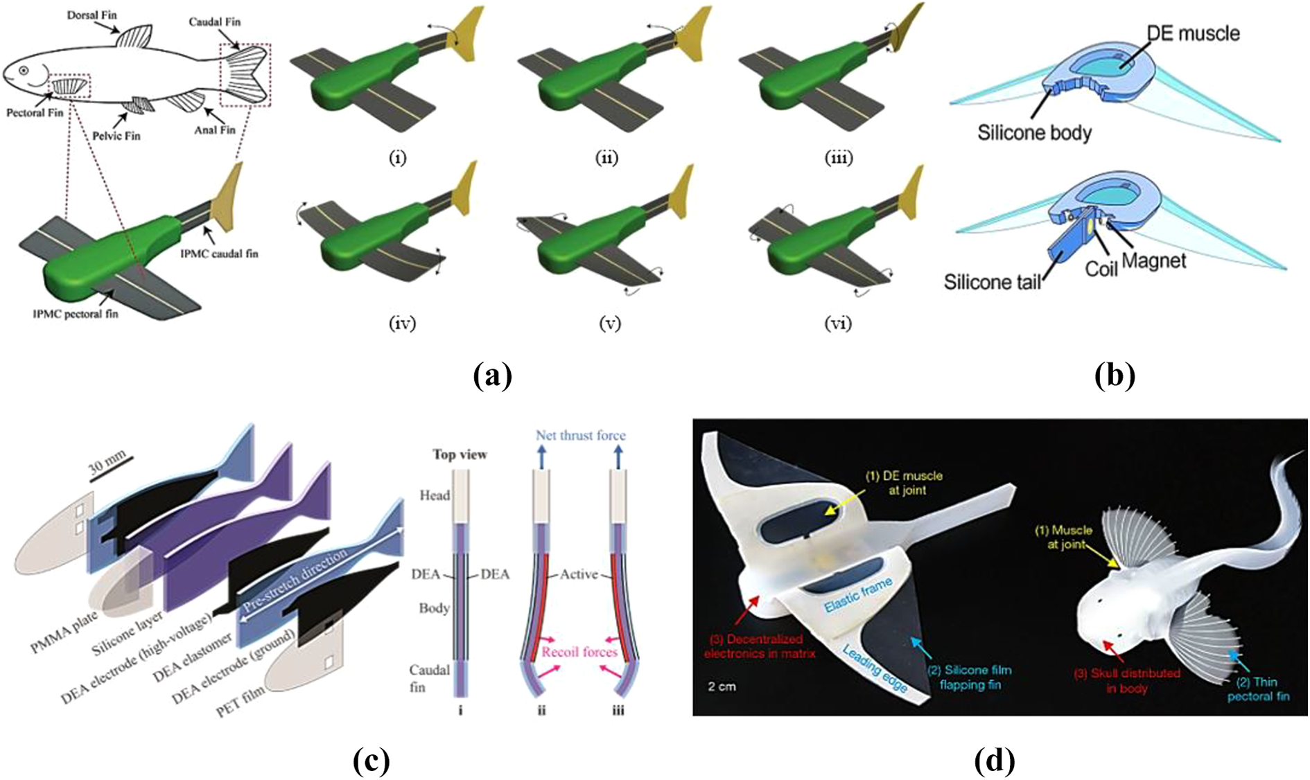
EAPs-based robotic fishes: (a) The deformable IPMCs lead to complex gestures of the robot: (i) Caudal fin bending “flapping”; (ii) caudal fin bending (nonneutral axis) “yaw”; (iii) caudal fin twisting “ roll/banking”; (iv) pectoral fin bending “translation/roll/banking”; (v) pectoral fin twisting “pitch-dive/surface”; and (vi) pectoral fin twisting “rolling”. Reproduced with permission. 81 Copyright 2014, IEEE. (b) The structure of the robot: the DE muscle is framed in the silicone body. A silicone tail attached to the body is for steering actuated by a magnet. Reproduced with permission. 64 Copyright 2017, Amer Assoc Advancement Science. (c) The robot composition: the body is assembled by two DEAs and two silicone layers. The head is made of a PMMA plate and two PET films. The positive DEA electrode is smaller and arranged inside of the body to realize insulation. Actuation structure: (i) pre-stretched state. (ii) and (iii) excited state: flaps the caudal fin to move forward. Reproduced with permission. 84 Copyright 2021, Mary Ann Liebert. (d) The structure of the self-powered soft robot inspired by snailfish (right). Reproduced with permission. 6 Copyright 2021, Nature Research. EAP: electroactive polymer; IPMC: ionic polymer metal composite; DEA: dielectric elastomer actuator; PMMA: polymethyl methacrylate; PET: polyethylene terephthalate; DE: dielectric elastomer.
The PPy actuator is fabricated by using electrochemical deposition to deposit PPy conductive polymer on both sides of polyvinylidene fluoride film to form a three-layer structure. 85 It will cause volume expansion to produce bending displacement when a small voltage is applied. This kind of actuator has the advantages of low cost, high conductivity, and fast response. McGovern et al. 86 described a method for measuring the thrust of a PPy actuator and studied the potential of the conductive polymer actuator as a robotic fish propulsion element by comparing the generated thrust with the synthetic speed of the robotic fish. A prototype 87 actuated by a PPy actuator reaches the maximum speed of 33 mm/s (0.25 BL/s) with a diameter of 20 mm.
For the DE actuator, when voltage is applied, the Maxwell stress is generated between the two electrodes and deforms the membrane in the thickness direction, resulting in area expansion. 88 DE possesses a fast response (less than 200 µs) and a large actuation strain (over 100%), but the applied voltage is relatively high (over 1 kV). 65 In order to deal with insulation problems, Li et al. 64 found that the conductivity of the surrounding open water is weak but sufficient to serve as the ground electrode, while the hydrogel film sandwiched by two DE membranes is another electrode. The leading edges of the fins are rigid to lead to the undulatory motions of the entire fins when flapping (see Figure 5(b)). Li et al. 6 developed a robot inspired by snailfish, which lives in the deep sea (see Figure 5(d)). The DE actuators are served as links between the fish body and fins. To adapt to the high pressure of the deep sea, they adopted a triblock copolymer, poly (styrene-b-butyl acrylate-b-styrene) in the DE actuator to increase the voltage-induced area strain. The robot succeeds in flapping for 45 min in the Mariana Trench (10900 m) and reaches a speed of 2.76 cm/s (0.24 BL/s) in the experimental condition of 110 MPa, which is a breakthrough in deep sea exploration. Shintake et al. 84 designed a prototype consisting of silicon substrate and elastomer membrane layers. They arranged the inside high-voltage electrodes smaller than other layers, making that there was no electrical short-circuit path through the water and thereby realizing the insulation (see Figure 5(c)). The swimming speed of the robot reaches a maximum of 37.2 mm/s (0.25 BL/s) with wired power.
PZT-based robotic fishes
The principle of PZT is based on the inverse piezoelectric effect, which results in structural deformation on electrical excitation. PZT actuators exhibit relatively high driving stress (about 110 MPa) and fast frequency, while the strain is relatively small (0.2%). 25 Typically, the robots actuated by PZT require a stroke magnification mechanism. Borgen et al. 89 used two THin-layer composite UNimorph ferroelectric DrivER and sensor (THUNDERs) (PZT actuator developed by Mossi et al. 90 ), respectively, connected to the tail fin. Although the magnifying mechanism is eliminated, the size of the actuator itself is large, which still makes the robotic fish bulky. The lightweight piezocomposite actuator (LIPCA), another PZT actuator, is superior to THUNDER in many aspects, but the driving displacement is still very small. Heo et al. 91 adopted a rack-and-pinion system to amplify the displacement (see Figure 6(a)). Nguyen et al. 92 used four layers of LIPCA connecting with a magnifying system to flap the fish tail (see Figure 6(b)). Zhao et al. 93 developed a micro-robotic fish (total mass: 1.93 g) with double caudal fins. The caudal fins are actuated by PZT bimorph cantilevers (36 mm, 2.1 mm, and 0.8 mm in length, width, and height, respectively) through a four-bar linkage transmission (see Figure 6(c)). The close or open movement is realized to improve the robotic stability and maneuverability when flapping. The maximum speed of the robot is about 4.5 cm/s (0.75 BL/s).

PZT-based robotic fishes: (a) The movement of LIPCA is transformed into the rotation of gears, which drives the rotation of the four-bar mechanism, thereby flapping the caudal fin. Reproduced with permission. 91 Copyright 2021, Springer. (b) When LIPCAs bend up, the flapping tail motion is realized through the long link and vice versa. Reproduced with permission. 92 Copyright 2010, IOP publishing. (c) Schematic of the micro-robotic fish and the movements of four-bar linkage transmission. Reproduced with permission. 93 Copyright 2021, Elsevier. (d) Structure diagram of the MFC-actuated bionic robotic fish. Reproduced with permission. 94 Copyright 2021, Academic Press-Elsevier Science. PZT: piezoelectric actuators; LIPCA: lightweight piezocomposite actuator; MFC: macro fiber composite.
Macro fiber composite (MFC), another type of piezoelectric material, comprises rectangular cross-sectional piezoelectric fibers and interdigitated electrodes. 95 In addition to good flexibility and large driving force, MFC strikes a balance between the deformation and actuation force, which means that the additional magnifying mechanism is not required. Govindarajan et al. 96 tested the performance of the MFC flapping beam underwater. They observed that the beam reached its maximum efficiency of 55% at the frequency of 2.0 Hz and the maximum thrust reached 45 mN. Cen et al. 97 created the first prototype actuated by MFC. It is a conceptual model that the piezoelectric MFC bimorph actuator (without caudal fin) is connected to the main body. The robot reaches a swimming speed of 7.5 cm/s (0.3 BL/s), which shows the feasibility of the MFC-actuated robotic fish. In addition, Tan et al. 95 designed a modular MFC bimorph tail connected to the body. With the actuation of the MFC actuator, the prototype reaches the maximum speed of 0.25 m/s (0.8 BL/s). Hu et al. 94 attached two MFCs to the caudal fin-like substrate. The MFC is 20 mm in width and 29.6 mm in length (see Figure 6(d)). They carefully designed a thrust measurement system, and the maximum mean thrust of 2.95 mN was observed.
FEA-based robotic fishes
FEA is integrated within and distributed throughout the body, which makes the robot soft and compliant. 66 FEA is made of super-elastic materials inside with several chambers expanded by pressurized gas or liquid, resulting in bending or stretching motion. Pneumatic and hydraulic actuators are two categories in underwater applications. Marchese et al. 98 developed a robotic fish that comprises two pairs of pneumatic layers longitudinally attached to an inextensible constraint layer (see Figure 7(a)). With an onboard gas regulation mechanism, the robot achieves escape maneuvers of a maximum heading angle of 100 degrees. However, the insufficient power supply resulting in limited endurance and the uncontrollable buoyancy center due to the release of gas are unignorable problems. In contrast, hydraulic actuators are capable of using surrounding water in a cycle, providing faster frequency response and larger force. Katzschmann et al. 4 adopted a similar actuator structure but used an onboard gear bump to pressure the fluid (see Figure 7(b)). The robot could dive up to 18 m and swim at the speed of 0.5 BL/s and show good integration into the marine environment.

FEA-based robotic fishes: (a) (i) antagonistic actuator, (ii) flexible and inextensible layer, and (iii) agonistic actuator. Reproduced with permission. 98 Copyright 2014, Mary Ann Liebert. (b) Overview of Soft robotic fish (top right). The elastomer tail (cut view) is driven by a gear pump, and the two inlets at the tail form a liquid circulation. Dive planes are driven by servos to ascend or descend. The buoyancy control unit, control electronics including an acoustic receiver, and fisheye camera are the subcomponents of the system. Reproduced with permission. 4 Copyright 2018, Amer Assoc Advancement Science. (c) Pre-stretched state (left) and the bending state of the FWBA (right). Reproduced with permission. 99 Copyright 2021, Elsevier Sci. FEA: fluid elastomer actuator; FWBA: flexible water hydraulic soft bending actuator.
Furthermore, Chen et al. 99 studied the relationship between the bending angle and the pressure of the fluid. They developed a flexible water hydraulic soft bending actuator (FWBA) for a fishtail as shown in Figure 7(c). The bending angle of FWBA is approximately 79.8 degrees with the water pressure of 18 KPa, and the bending angle drops to 56.5 degrees with the water pressure of 20 KPa when paired FWBAs are adopted to flap a caudal fin.
Sensors for robotic fishes
Sensing technology is an essential part of the robotic fish. It can sense changes in the surrounding environment to provide feedback control. Generally, in terms of realizing autonomous navigation, infrared sensors are mainly used in the detection of obstacles, effectively in planning routes, and avoiding obstacles. Pressure sensors are used for depth perception to prevent excessive pressure from damaging components. Accelerometer and gyroscope are used to maintain the stable swimming of the robotic fish. Compass realizes the direction recognition. The current sensor predicts battery life and provides variable current to the robot. Force/torque sensor measures thrust. More details are presented in Table 4.
Different types of sensors used in robotic fishes.
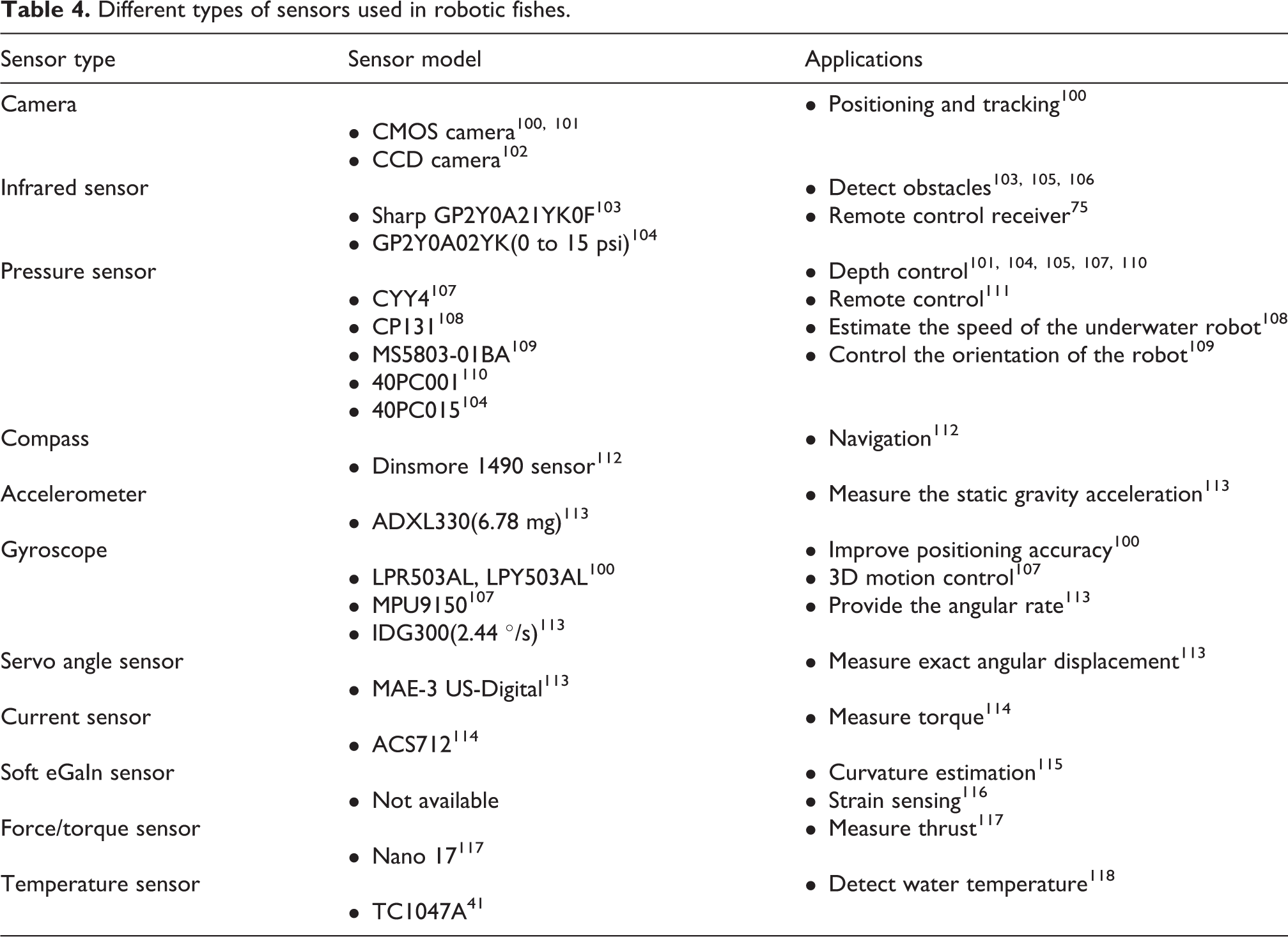
As an important part of underwater perception, artificial lateral line (ALL) has received more and more attention. The lateral line system is a unique skin sensory organ of aquatic vertebrates. 119 The basic sensory unit of the lateral line is the neuroma, which is a receptor organ that consists of sensory hair cells and support cells covered by a gelatinous cupula. 120 The ALL system inspired by it uses pressure sensors as the main sensing components. Multiple pressure sensors are distributed on the surface of the fuselage. Specifically, Wang et al. 121 distributed nine pressure sensors around the body to perceive the state of adjacent robotic fish by sensing the reverse Carmen vortex street. Zheng et al. 122 distributed eleven pressure sensors on the fuselage: four at each side of the shell, one at the tip of the head, and two at the top and bottom of the head. The state of adjacent fish was obtained by collecting hydrodynamic pressure variations data. Furthermore, piezoresistive, piezoelectric, capacitive, optical, and hot-wire sensors can be used to build ALL systems as well. See literature 123 for more details.
Modeling and control of robotic fishes
Modeling and control are considered to be the core parts of the robotic fish design. In this section, the methods of dynamic modeling are first presented. Then, two main control approaches: (1) trajectory approximation method and (2) central pattern generators (CPGs) are reviewed.
Dynamic modeling
Due to the complexity of the morphology and hydrodynamics of fish, it is very difficult to establish an accurate dynamic model. The numerical method and analytical method are typically adopted. The former often requires the establishment of N–S equations. Computational Fluid Dynamics (CFD) is applied to numerical simulations. Using the CFD method based on the N–S equations, the viscous force can be fully considered, and the unsteady and nonlinear effects caused by the tail swing can be analyzed, which makes the hydrodynamic prediction more reliable. 124 However, this method is very time-consuming due to the huge amounts of calculations, and it lacks the support of classified and fined experimental data. The latter, based on certain simplifications, is more feasible but less accurate. For instance, the Resistive Force Theory 13 is only suitable in the low Reynolds number condition for neglecting the inertia force. The WPT 15 simplifies the fish body as a flexible thin plate for wave motion, thereby being more suitable for the flatfish swimming. The EBT 14 is suitable for slender fish with small lateral deformation. It presents that the thrust of the fish is generated by the additional momentum corresponding to the motion of the fish body wave propagating backward. Based on the momentum balance in the hemisphere control volume containing the fish body, the effect of wake dynamics is also approximated. The large-amplitude elongated-body theory 18 proposed later extends its applications to larger lateral deformation, which makes it the most acceptable theory. In addition, Yu et al. 125 proposed a data-driven approach. In their method, the dynamic model is first derived with the Morrison equation and the strip method, and the parameters are directly identified from experimental data and integrated into the dynamic model to reshape it. Therefore, it is applicable to model swimming robots with complex and irregular geometric profiles and numerous heterogeneous hydrodynamic parameters.
Trajectory approximation
To approximate the trajectories of the fishes, it is important to get a deep understanding of the principles of their locomotion, which is characterized by the deforming bodies. A widely adopted function of the traveling body wave is proposed by Lighthill 14

where

where

Then, the function is discretized to fitting the body wave

where i is a serial number in an undulation circle and M represents the resolution of the discrete travelling wave. Therefore, a
Similarly, other swimming patterns could be realized by establishing corresponding kinematic functions. 127 In conclusion, this method is easy to implement but could not realize smooth gait transition, and the instantaneous torque changes and jerky movements have the risk of damaging the motors and gearboxes. Moreover, the online parameter tuning is difficult since each joint involves many values to promise accuracy.
Central pattern generator
Another control method is to use CPG, which is a neural network that exists in both invertebrates and vertebrates. It can generate rhythmic neural activity patterns, such as respiration, chewing, and sucking, in the absence of external signal input like sensory feedback or higher control centers. 128 In biology, CPG is turned out to be a distributed network composed of several coupled oscillators, which is suitable for multi-link mechanisms. 129 In particular, the oscillators are coupled in a certain topology, and each of the oscillators is in charge of a specific joint. Simple or low-dimensional input signals are sufficient to propose the coordinated wave motion of the robot. CPG-based controller exhibits superiorities: (1) provides stable rhythmic patterns, (2) realizes diverse motion modes of the robot through a variety of stable phase relationships, (3) presents smooth transition online between different gaits with simple control parameters, and (4) although CPG does not require sensory feedback, they are crucial to shaping the CPG control to improve adaptability and robustness.
CPG models
The first step to construct a CPG controller is to choose an appropriate CPG control model. The most widely used CPG model in a robotic fish domain is the oscillator model, of which the most common are the Hopf oscillator and the Ijspeert phase oscillator.
Hopf oscillator possesses a stable limit cycle. 130 It is able to produce sinusoidal oscillation independently. The dynamics of the Hopf oscillator could be described by the following differential equations

where x and y are the states of the oscillator,
Ijspeert et al. 131 developed a phase oscillator to control a salamander robot. The oscillator could be described as follows


where
Parameter tuning
Parameter tuning is the key problem in CPG modulation, as the CPGs involve many uncertain parameters in the equations while a well-established design methodology for CPGs to achieve the desired motion behavior is still missing. Lately, some intelligent learning methods are being proposed. Yu et al. 132 searched the optimized parameters by integrating particle swarm optimization (PSO) and a dynamic model. In PSO, each particle has the ability to perceive the best position of itself and the swarm and then adjust its actions based on this information by iteration. Specifically, the dynamic model is first developed as a guide to search the control parameters and the swimming patterns, and then, the PSO refines the searched parameters of the CPGs. Zhou et al. 133 adopted the genetic algorithm (GA) to optimize the parameters of the CPGs as GA possesses high-dimensional global searching capability. The speed and the instantaneous swimming power consumption are used as feedback to improve the controlling parameters by GA. Hu et al. 134 proposed a learning method to acquire fishlike swimming. First, they used the trajectory approximation method to obtain the joint angles as the teaching signals. By converting the parameters of frequency, phase difference, and amplitude into new state variables with their own dynamics, the teaching signals and their phase relations could be learned by the CPG network, thus the instructed locomotor pattern can be reproduced by the robotic fish. The learning is embedded into the dynamics of the oscillator, thereby external optimization or preprocessing of the teaching signal is not required. Ren et al. 135 proposed a general internal model (GIM)-based learning method. The GIM is composed of three components, namely the inner Hopf oscillator, the artificial neural network (ANN), and the outer signal modulator. The Hopf oscillator generates periodic input signals. The ANN is trained to yield the desired motion patterns when receiving the input signals from the inner Hopf oscillator, and the outer signal modulator adjusts the amplitude of the generated motion pattern according to task specifications since the output of the ANN cannot be resized by the input as the ANN is a nonlinear mapping. The GIM exhibits excellent function approximation ability, and the speed and direction control are realized by monotonically tuning parameters.
Close-loop CPG system
The close-loop CPG system plays a very significant role in the generation of diverse and stable movements. The framework of closed-loop control is schematically shown in Figure 8. Specifically, the sensory signal generated by them could directly act on the CPG, like a reflex action, which is an involuntary and nearly instantaneous movement in response to a stimulus, or received by the high-level center as feedback. Due to the nonlinear environment, the fuzzy or (proportional–integral–derivative) controller is adopted as the high-level center to decide the swimming mode based on the feedback. The gait transition could be realized by a finite state machine (FSM) since each gait corresponds to a set of control parameters. The combination of the CPGs and the FSM provides an effective way to switch locomotor patterns. Under this frame, Bal et al. 136 realized excellent autonomous swimming performance through precise yaw control. Yan et al. 137 achieved stable motion mode switching between swimming and crawling.

The schematic of the close-loop CPG system. CPG: central pattern generator.
Challenges and future directions
With the unique driving characteristics and application diversity, robotic fish will certainly become one of the major development trends in performing underwater tasks. However, there is a gap between the robotic fish and the real fish regarding the performance. The maximum speed of the robotic fish is 3.7 m/s, which is far more outstanding than others, while the swordfish reaches about 27 m/s. The maximum turning speed of the robotic fish is 670 °/s, while the archerfish is 4500 °/s. Moreover, fishes exhibit flexible and freely maneuvering, such as escape, rapid acceleration, and braking, while the robotic fish only execute simple turning or diving. The possible directions of robotic fish might focus on the following aspects.
First, one possible direction is drag reduction, which might contribute to the high speed of real fish inspired by Gray’s paradox. 12 The micron-scale caves distributed on the fish surface play an important role in drag reduction. 138 The concave shape creates a negative pressure area, sucking oil out of the hole to lubricate the surface to minimize frictional resistance. Dou et al. 139 developed a coating technology that autonomously forms the micron-scale caves when swimming. The gas-phase develops in the solid–liquid interface in low-pressure conditions due to flow separation and vortex and partially replaces the solid–liquid shear force with gas–liquid shear force, resulting in drag reduction. It is noteworthy that the drag reduction efficiency of the bionic surface becomes more significant as the flow rate increases (over 10% at the flow speed of 13.1 m/s). In the future, the drag reduction mechanism needs to be clarified, and more remarkable performance and simple fabrication of drag reduction technology are needed to be adopted in the robotic fish system.
Second, the question of improving the actuation system is another direction. On the one hand, the prototypes based on the multi-link mechanism actuated by the traditional DC and servo motors still represent the state-of-the-art swimming speed. However, it cannot perfectly fit the flexible movement of real fish, and the friction loss caused by additional transmission mechanisms cannot be ignored. Furthermore, it requires multiple motors to independently drive the fin rib to reproduce the undulation of ribbon fins, which is bulky and difficult to control. The design of MAR, using a single helix to realize undulation, shows a new direction of actuation system simplification. 34 On the other hand, the smart materials and soft actuators can be well integrated into the body of the robot fish with a smaller size and higher maneuverability, but most of the robotic fish with such actuators have a maximum speed of no more than 3 BL/s. 31 The FEA shows high compliance and the best “biomimicry”. This actuator is essentially powered by motors but uses fluid as the energy conversion medium, which gives it the advantages of high speed and flexible movement, especially the form of hydraulic exhibits great promise in terms of stability and energy recyclability. In the future, it is expected to be applied to undulation and muscle-like movements.
Third, the underwater perception is still not well-developed. Powerful perception offers detailed feedback in control and improves the adaptability of the robotic fish. However, current sensors, such as cameras, IMU, and GPS, have difficulty performing well in the harsh underwater environment. Moreover, they could only provide a single sensing signal and had blind areas, where they unable to sense objects or creatures’ subtle movements. 140 Lateral line is an important modality to sense the subtle changes in the water flow, which is composed of a row of neuromasts distributed throughout the fish body. 120 Based on it, the ALL is typically constructed by an array of distributed pressure sensors to sense the fluid velocity or reverse carmen vortex street, which is crucial to the perception among groups of underwater robots. 141 However, it is still worth exploring how to realize real-world perception. Recently, the increasing interest in proprioceptive sensing provides a new direction for underwater perception, which utilizes the kinematics or parts of the body to extract useful information inflow. 142 Since related research studies are just beginning, future directions might include determining the type of proprioceptive signal perceived and clarifying the neurotransmission mechanisms between proprioceptive and motor control. 143 From a long-term perspective, it is exciting to combine proprioceptive sensing with an ALL to realize powerful underwater perception.
Fourth, the control methods are needed to be improved. The close-loop CPG system has strong adaptability and robustness. However, how exactly the properties of sensory information affect the characteristics of the CPG output has not been fully investigated. Recent studies have shown that sensory feedback topology has a significant impact on the way that the neural oscillator setting affects the entrainment characteristics of the coupled system. 144 In general, a systematic design method for sensory feedback control is needed to be developed in the future. Alternatively, considering the complexity of nonlinear hydrodynamics, the iterative learning control could be regarded as a potential candidate. 145 The accurate model is not required when an appropriate learning gain is chosen. The learning formulates the input signal based on previous experimental data, and good speed tracking performance is achieved with constant iteration during the entire operation interval. In the future, it is expected to be applied in tracking maneuvering movements, such as turning, yawing, or pitching motions.
Conclusions
In this article, we have reviewed the characteristics of different fish locomotion and the robot designs based on it. We also have outlined features of smart soft actuators and sensors. Then, we have summarized modeling and control methods for efficient and stable swimming. Fish have many complex structural features, most of which are not yet known clearly for their potential impact on swimming performance. However, it is certain that the use of mechanical devices for imitation is a sure way to help us understand the hydrodynamic principles of fish movement and thus achieve the transcendence of the real fish. The robotic fish is still in the preliminary prototype development stage, and there is still a certain distance from the practical application, but with its excellent potential performance, it will certainly expand a wide range of applications in military and civil applications.
Footnotes
Acknowledgments
This work was supported by the Zhejiang Provincial Natural Science Foundation of China (Grant Nos. LY22E050019 and GG21E050044) and the National Natural Science Foundation of China (Grant Nos. 51805482 and 51975523).
Declaration of conflicting interests
The author(s) declared no potential conflicts of interest with respect to the research, authorship, and/or publication of this article.
Funding
The author(s) disclosed receipt of the following financial support for the research, authorship, and/or publication of this article: This research is funded by natural science foundation of zhejiang province (GG21E050044 and LY22E050019) and national natural science foundation of china (51805482 and 51975523).