
Abstract
The purpose of this study is to realise numerical control (NC) gear cutting on the split wheel blank of equal-base bevel gears, based on the instantaneous cutter position information in tooth surface forming and NC machining theory, the coordinate system of split equal-base bevel gears is established. According to the movement of tool centre coordinate and its transformation, the linear motion of machine tool is solved. By the rotation and translation of the tool axis vector, the solution of the rotary motion of the machine tool is obtained. According to the different rotation direction and concave-convex property of tooth surface, the calculating model of the starting point of processing of each tooth surface is deduced. The complete machining trajectory is formed by analysis and extension of the tool starting point and terminal point of machining, and the automatic generation of the NC machining program is realised. Finally, the simulation of gear cutting on the split wheel blank is carried out using VERICUT software. The experimental and tooth surface measurement results show that the mathematical model of motion trajectory is correct and the machining method is feasible.
Keywords
Introduction
Extra-large bevel gears are core components of large-scale key equipment, which are used extensively in important fields such as power generation, ships and mines. To date, the extra-large bevel gears used in key equipment have all been straight bevel gears,1–3 and the split structure has often been adopted in existing extra-large straight bevel gears.
The equal-base circle gear is a new type of curved tooth bevel gear. 4 Compared to the straight bevel gear, the equal-base circle gear exhibits certain advantages,4,5 such as strong carrying capacity, good transmission stability, small impact and low noise. The wheel and pinion of equal-base circle gear are formed by finger-shaped milling cutters with a general machine tool, and the machine tool structure is simple, while the cost of the cutter applied in the machining is low. Furthermore, tooth surface machining of the equal-base circle gear can be achieved by a two-axis linkage machine, making it easy to apply tooth machining following wheel blank splitting. In addition, the spiral angle of the equal base bevel gear is small, which is suitable for splitting along the tooth space. Under the principle of not damaging the tooth surface, the dividing path is generally designed as the connecting line at the midpoint of the outer and inner ends of the tooth space. Because of its simple machining principle, it is easy to improve the machining accuracy through the correction of the tool moving path and the cutting depth. Thus, the extra-large equal-base circle bevel gear is an ideal curved bevel gear for replacing the existing extra-large straight bevel gear.
In the field of equal base bevel gear, Cai and Cheng 6 proposed the concept of equal-base bevel gear and the method of NC form copying with a finger-shaped milling cutter, and verified the feasibility of NC machining through experiments. Cui and Shi 7 deduced the offset curves equation of the tooth line, and on this basis, analysed the geometric structure characteristics, machining methods and tool design of the equal base bevel gear. Gong et al.8,9 made a deep and systematic study on the transmission principle, tooth surface geometry, tooth shape error, tooth modification and meshing characteristics of the equal-base bevel gear by using modern calculation methods. Zhang et al. 10 carried out the analysis and research on the meshing characteristics, tooth surface geometry and modification of the equal-base bevel gear. Zhang et al. 11 researched deeply on the two-axis CNC machining theory of equal-base bevel gear, on this basis, a large size equal-base bevel gear was actually machined with the finger milling cutter. Deng et al. 5 studied the NC machining theory and method of equal base bevel gear with a pot-shaped milling cutter, and verified the tooth surface machining accuracy and NC machining method through theoretical analysis and experiment. All the above researches on the equal-base bevel gear are based on its integral machining, but there is no report on the research of the extra-large equal-base bevel gear, especially the split extra-large equal-base bevel gear.
According to the existing cutting theory of curve bevel gear, when it is processed by NC machine tool, the gear rotation centre must coincide with a rotation axis of the machine tool,12–15 which is a necessary condition for two-axis linkage machining of the equal-base circle bevel gear. In addition, only in this way, the indexing movement of the wheel blank can be realised. For the extra-large equal-base circle bevel gear, particularly when the diameter reaches approximately 3500 mm, few devices can meet this requirement. At this moment, it is a good choice to cut the wheel blank into several equal parts and then to machine the teeth. Therefore, when machining a separate block of the split extra-large equal-base circle bevel gear on a small-size machine tool, the rotary centre of the wheel blank is located outside the machine tool, the original motion control theory of cutting gear is no longer applicable and indexing during the machining process cannot be realised with ease. Split the wheel blank before machining tooth surfaces makes the tooth surfaces machining trajectory on a split wheel blank changeable and the control of tool attitude complex. In this situation, even for the tooth surface with the same rotation direction and same concave or convex characteristics on the same split wheel blank, the instantaneous attitude of tool, the starting point and the end point of tool movement are different. In addition to the particularity of the tooth surface of equal base bevel gear, the existing NC machining software can not program it automatically. Therefore, the NC cutting programme on split wheel blank is complex and the programming workload is large. How to generate the NC machining programme quickly and accurately is a key link to realise the gear cutting. With the rapid development of computer technology, great progress has been made in the fields of tooth surface precision modeling, simulation processing, error compensation,16–20 etc. The development of five-axis NC machining technology21–23 and its application in gear surface machining make it possible to NC machining this kind of split gear. 24
In the previous research of this research group, the tool position solution in machining process has been completed, the projection component of tool axis vector on the three coordinate axes is not always zero, five axis linkage machining is needed. Based on the premise that the tool position information is known, taking the split wheel blank as research object, and according to the NC machining theory, a general mathematical model for calculating the straight-line movement and rotary movement in NC cutting gear is derived and established, the problems such as the calculation of starting point, the cutting in and out path of tool, and the automatic generation of NC machining program are systematically studied, and actual machining process are carried out to verify these. The research has certain scientific significance and engineering application value for the manufacture of super large split bevel gear.
For this purpose, the paper is organised as follows. The section ‘Machining motion calculation of machine tool’ presents the detailed components of post processing to cutter position information, the complete NC machining trajectory generation and the NC program automatic generation. Section ‘Simulation processing and experiment’ reports the whole process of simulation machining, the experiments and tooth surface measurement. Conclusions and further developments are drawn in section ‘Conclusions’.
Machining motion of machine tool
Based on the theory of equal-base bevel gears, the tool coordinate system is established in the wheel blank coordinate system, and then the tool centre and tool axis are moved and rotated according to the instantaneous position and attitude of the tool, and the tool centre and tool axis vector corresponding to each instantaneous is solved. Considering the structural layout of general machine tools, and the position of split wheel blank on machine tools, the expression function of the machine tool motion is solved by post processing.4,5 Through the research on tool starting point, end point of cutting and the machining program generation automatically, finally, NC cutting motion of split wheel blank is realised.
Linear motion
For the known tool centre coordinates and tool axis vectors in the wheel blank coordinate system, the post-processing is used to transform them into the motion coordinates of the machine tool. Without loss of generality, taking

Coordinate systems in the split gear machining.
Combined with Figure 1, the coordinate systems are explained as follows:
Compared to the fixed coordinate system, the wheel blank coordinate system is rotating, and its each rotation position corresponds to a processed tooth surface. Therefore, the transformation matrix from the fixed coordinate system to the wheel blank coordinate system will change according to the value of angle
In order to determine the relationship between the rotating wheel blank coordinate system and the fixed coordinate system, the value of

where
The transformation matrix from the wheel blank coordinate system to the transition coordinate system is set as

where
The transformation matrix from coordinate system

The transformation matrix from coordinate system

Before solving the NC machining path, the tool position information has been obtained, which is a known vector. Here, set the cutter centre vector is
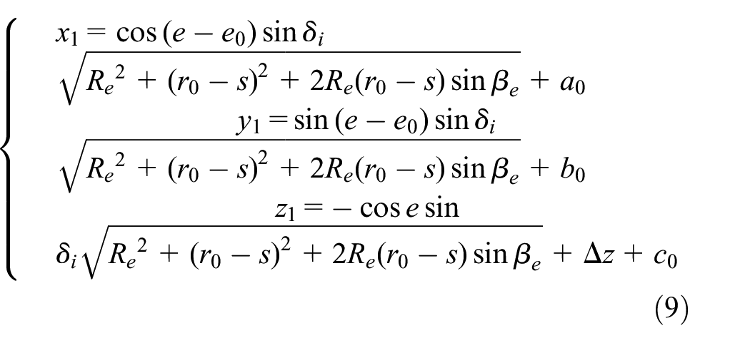
Substituting the parameter formula into the above equation, simplifying the equation and get

In equation (5)
Rotary motion
In the same way as

According to the principle of post-processing and the cutter axis vector obtained in equation (6), calculating the actual rotation angle
The initial tool axis vector is generally inconsistent with the direction of machine tool spindle (axis
For this purpose, the starting point of the cutter axis vector

Rotation relationship of the cutter axis vector in post processing.
The arrow in the rotation direction shown in Figure 2 means the axis
The following sections are the derivation and special case description of the calculation of angle

Two situations of angle
From Figure 3 and triangle function, the calculation formula of angle A is

Assuming the projection vector of

Four possible cases of angle
From Figure 4 and triangle function, the calculation formula of angle

Special case, when
Theoretic starting point
There are two theoretic starting points at the outer of tooth space corresponding to the concave and convex surfaces, the feature points
The tool moves from the outer to the inner when machining different tooth surfaces of equal-base circle bevel gears. So, substituting
The value of
Where,
After getting the coordinate of the theoretic starting point, combining with equation (5), in MATLAB environment, the machining paths of convex and concave tooth surfaces on both sides of each tooth space can be calculated and drawn. In order to visually observe the tool processing path, calculation and drawing has been performed for a split equal-base circle gear which design parameters represented in Table 1, what’s more, the wheel blank is divided into six equal sections in this example.
Basic geometric parameters of gear pair.

It should be pointed out that it’s no problem whether the splitting wheel blank can be divided equally or not, the number of teeth on each split separate block can be the same or different, which has no influence on the automatic generation of processing programs and NC processing.
In MATLAB environment, the processing paths of the example are shown in Figure 5.
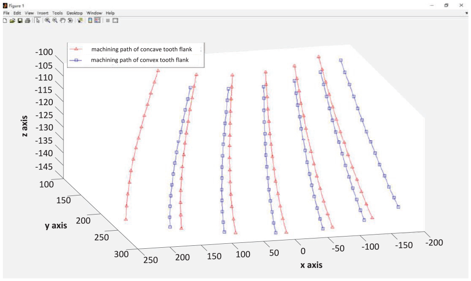
Machining paths of tooth surface (excluding the cutting-in and cutting-out paths of tool).
Extension of starting point
In the actual NC machining process, the tool is impossible to be at the theoretic starting point immediately when the tool is started and turned. Therefore, there is still a section of feed path which needs to be planned reasonably before the tool cuts into the theoretic starting point. This is to ensure that the cutter can gradually enter the theoretic starting point and avoid bumping the workpiece. As can be seen from Figure 5 each machining path is a spatial curve, so the best feed path is the natural outward extension of the machining path curve.
MATLAB software provides two-dimensional interpolation function interp2 (x, y, z, XI, YI), the parameters (x, y, z) are solved by the machining path coordinates in equation (5), the parameters XI and YI can be appropriately evaluated on the outer of the wheel blank according to the coordinate range of the theoretic starting point.
As the tool does not touch the workpiece in the start position of feed path, the value of XI and YI do not need to be precise, as long as the tool can move smoothly along the feed path to the theoretic starting point without collision.
Based on the above analysis, interpolation operation is done on the outside of the theoretic starting point, and several discrete points are obtained, which can be used as the feed path, the feed path in the example is shown in Figure 6:

Machining paths of tooth surface with the cutting-in paths.
Extension of terminal point
When the tool moves to the inner of wheel blank from its outer, in order to ensure that the tool can safely exit the workpiece, and avoid the tooth surfaces of both sides of the tooth space being damaged accidentally, so, it is necessary to plan the tool exiting path reasonably.
Similar to the processing of theoretic starting point, interp2, a two-dimensional interpolation function in the MATLAB programming environment, is used to extend the machining path at the end of the tool path. By interpolation operation, several tool withdrawal points can be inserted appropriately, the tool withdrawal path planning is completed. The tool withdrawal path in the example is shown in Figure 7.

Machining paths of tooth surface with the cutting-out paths only.
Up to this point, we get the complete machining path includes feed path (the path for cutter to cut in), machining path and withdrawal path(the path for cutter to cut out), the complete machining path in this example is shown in Figure 8.
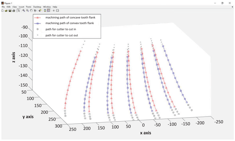
Complete tool centre trajectory.
NC programme
For the split equal-base bevel gear, the NC machining program of each tooth surface on it is different, and the data volume of processing parameters is huge. Normally, each coordinate needs to be input manually and accurately during programming, this is inefficient and prone to error clearly, and it is not easy to modify the program frequently. Therefore, through the reasonable design of the MATLAB program, with the automatic reading and writing function of the software, all the coordinate data will be saved to the program after the main program is completed.
Then write a subroutine to automatically generate NC code, automatically extract the coordinates of the corresponding points and write the programming code at the location, where the coordinates need to be entered. In the program, you can specify the saving path of the corresponding code file. This greatly improves the programming efficiency. Even changing the parameters of bevel gear, the new NC machining code can be generated quickly and accurately.
In MATLAB environment, the fopen function can be used in a custom path to build and open a text file, and then by calling the fprintf function, data will be written to the text in the specified format file. After the data is written, the fclose function is called to close the file. Before running the program that generates the NC machining code automatically, you need to run the main program first so that the coordinate values of all points are stored in the program. Then combine the built-in functions mentioned above, the NC machining code can be quickly generated through the circular call of variables.
Taking the first convex tooth surface of the split wheel blank as an example, which design parameters represented in Table 1. The program example of automatically generating NC machining code in Matlab environment is as follows:
‘NC machining code of convex tooth surface’;
% Name of the program.
fid=fopen(‘D:\…\01.nc’,‘wt’);
% Create a
fprintf(fid,‘G90 G00 A%f B%f\n’,A1(1),B1(1));
% Enter the G code instruction: G90 G00 A-15.9774 B9.3186…
for i=1:length(in_x01);
fprintf(fid,‘X%f Y%f Z%f \n\n’,in_x01(i),in_y01 (i),in_z01(i));
end;
% Loop to get and enter the coordinates of the incoming of tool points: X227.508838 Y236.175600 Z-149.396094…
fprintf(fid,‘G01 F800\n’);
% Enter the G code instruction: G01 F800.
for p=1:length(A1m);
fprintf(fid,‘A%f\t\tB%f\n’,A1m(p),B1m(p));
fprintf(fid,‘X%f\t\tY%f\t \tZ%f\n\n’,AX01(p),AY01(p),AZ01(p));
end;
% Obtain and input machine tool motion coordinates automatically: A-15.9917 B9.2936.
X215.049300 Y212.42100 Z-140.364900…
for o=1:length(out_x01);
fprintf(fid,‘X%f\t\tY%f\t \tZ%f\n’,out_x01(o),out_y01(o),out_z01(o));
end;
% Loop to get and enter the coordinates of the tool withdrawa points: X110.390925 Y124.490700 Z-98. 618757
fprintf(fid,‘\nM17’);
% Exit the subroutine call and return to the main program.
fclose(fid);
% After the file is written, save and close the file.
In order to illustrate the basic design idea of the above program, a concise flow chart is shown in Figure 9.
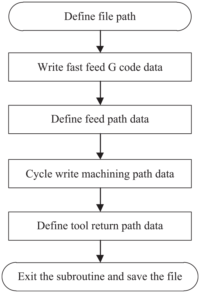
Concise program structure flow chart.
For the split wheel blank of the example shown in Table 1, the complete NC code generated by the above program will be used in subsequent processing experiments. Because the NC code is huge and limited to the length of the paper, the NC code is not listed here.
Simulation and experiment
In order to verify the correctness of mathematical model, and the feasibility of machining split gear in practise, the machine tool modeling, cutter modeling and split wheel blank modeling are carried out respectively according to the actual situation in this section. For the gear shown in Table 1, the machining trajectory calculation and NC programming are carried out according to the above mathematical model. With the help of VERICUT software, the cutting simulation is completed. On this basis, processing experiments and tooth surface measurement are carried out.
Simulation process
The machine tool needs three moving motions (X/Y/Z) and two rotary motions (A/B), according to the solution of the machining motion trajectory above. Also because the motion of the machine tool is complex in the cutting process, it is necessary to build the machine tool model by the third-party software. So, in INVENTOR environment, All the components of machine tools are modeled. Then, importing each component module of the machine tool into VERICUT software in turn, adjusting their assembly relationship and defining all the coordinate systems, building final model of machine tool as shown in Figure 10(a).

Model of machine tool and simulation: (a) model of machine tool and (b) simulation cutting interface.
Thereafter, for the above example presented in Table 1, the tool profile is calculated according to the gear design parameters, and the profile parameters are input in the tool management of VERICUT, the tool model is built.
Next, the machining movement tracks are calculated by the formulas deduced previously, and the NC machining codes are automatically generated by the method mentioned above. Then the subroutines of different convex and concave surfaces are established respectively, and the execution sequences of the subroutines are adjusted according to different cutting path plans. Thereafter, the main program calls the subroutine, the simulation process can be completed. Figure 10(b) is the overall simulation interface includes the machine tool, the wheel blank and the tool.
Machining experiment
On the basis of the above simulation, machining experiment is carried out on a five-axis CNC machine tool. According to the gear parameters in Table 1, the split gear billet is designed and processed, which material is aluminium alloy. In order to reduce the cutting force and the tool wear in finishing, rough slotting was carried out with standard tools before finishing. Fine milling cutter is designed according to the gear parameters in Table 1, and a special cutter bar is designed and manufactured. The cutter is connected with the spindle of the machine tool through the cutter bar and a spring chuck. The processed photographs and the finished product photograph are shown in Figure 11.

Processing photos.
Because of the particularity of the equal-base circle bevel gear, the existing gear measuring centre can not detect and analyse the tooth surface. Therefore, the tooth surface measurement after machining is carried out on the coordinate measuring machine. Fifty-five measuring points are taken on the whole tooth surface. The measured values are compared with the corresponding points on the theoretical tooth surface by C language programming.25,26 The photograph of the measurement site is shown in Figure 12, and the analysis result of tooth surface is shown in Figure 13.
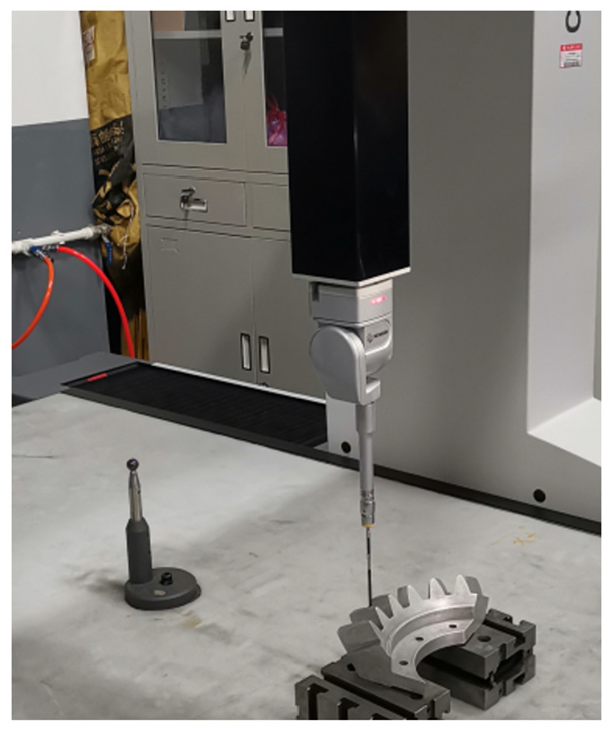
Tooth surface measurement.

Analysis results of tooth surface.
In the figure, the fine solid line represents the theoretical tooth surface, the blue solid line represents the machined tooth surface, the positive number represents the machined tooth surface overcutting and the negative number represents the machined tooth surface undercutting. As can be seen from the graph, convex surface is overcut more, concave surface is undercut more and the error at outer is greater than that at inner. The errors in root and top parts of teeth are larger, while the errors in middle part of teeth depth are smaller. For large size split gear, it can fully meet the engineering requirements.
Conclusion
The manufacture of super large assembled bevel gears includes many technical links, the research in this paper completed the NC machining research and feasibility verification of the tooth cutting on split wheel blank, based on the research conducted, the following conclusions can be drawn:
The study results suggests that the NC machining trajectory of the split equal-base circle bevel gears is solved correctly, and this new idea of cutting teeth is feasible.
The calculation and analysis of the tool starting point and terminal point in gear cutting are correct, and the research of automatic generation of NC machining program is feasible.
This research offers certain scientific significance and engineering application value, especially for machining super-large bevel gears on small-size machine tools. However, because the research is based on the special finger milling cutter, the tool design and manufacturing are troublesome, so it has its limitations in practical . Using general tools, such as ball end milling cutter or bar milling cutter, machining the tooth surface is worthy of further research.
Footnotes
Acknowledgements
The author would like to thank the first tractor factory in China, for their technical support and help in gear processing and measurement.
Handling Editor: Yuansheng Zhou
Declaration of conflicting interests
The author(s) declared no potential conflicts of interest with respect to the research, authorship, and/or publication of this article.
Funding
The author(s) disclosed receipt of the following financial support for the research, authorship, and/or publication of this article: This work was supported by the Key Scientific Research Projects of Colleges and Universities in Henan Province of China (No. 19A460020).