
Abstract
Slewing bearings are critical components of rotating equipment. Large structure sizes and heavy working load conditions require an extremely high load-bearing capacity and reliability. Overall and local contact finite element models of slewing bearings are verified by the empirical formula and Hertz contact theory. Validated finite element models are used to analyse the influence of the elastic material (E 1) and elastoplastic material parameters (EP 1, EP 2 and EP 3) on the load carrying capacity. The following conclusions are obtained by comparing the maximum contact load, the contact stress, the load distribution and the full-circle deformation. The influence of the material parameters on the slewing bearing is investigated to improve the analysis accuracy of the carrying capacity of the slewing bearings.
Keywords
Introduction
Slewing bearings are critical components of large-scale rotating equipment, consisting of rolling elements, inner rings, outer rings and isolation blocks, as shown in Figure 1. 1 They are used in relative rotation conditions and to transfer loads between two parts. The application fields range from the earliest traditional construction machinery to wind power generation, medical equipment, military applications, food processing, entertainment and other fields. The hard working environment, heavy loads and initial defects of the blank material easily cause damage to the slewing bearing. Moreover, the replacement and maintenance of the slewing bearing is time-consuming and expensive. Therefore, the carrying capacity and reliability are the main concerns for slewing bearings.

Single-row four-point contact slewing bearing.
Regarding the carrying capacity of slewing bearings, many scholars have used static mechanical models to study the load distribution, circle deformation and contact stress. Xuehai et al. 2 established a finite element model to analyse the influence of structural parameters on the carrying capacity, and the results were compared with the engineering experience formula results and Hertz contact theory results. The theoretical calculation results of the maximum contact load are larger than the finite element calculation results. Some researchers3–5 used the balance equation of ball slewing bearings to study the influence of ferrule deformation, connecting bolts and flexible supporting structures on the carrying capacity. The results show that the flexible supporting structure and the deformation of a ferrule have a great influence on the carrying capacity of a raceway. Olave et al. 6 obtained the load distribution of a slewing bearing by the finite element method and the calculation methodology. The influence of the structure’s elasticity was considered, and the two methods showed quite consistent results. A rigid ferrule is assumed in many studies when calculating the load distribution. Deformation occurs only between the rolling element and the raceway, and the influence of the uneven deformation of the ferrule and the supporting structure is not considered. This assumption is sufficient for the accuracy of the ordinary bearing calculation. However, the bending and torsion deformation of the slewing bearing cannot be ignored due to the large size of the bearing ring, complex load situation and relatively small ferrule stiffness.
Researchers use nonlinear structures instead of rolling elements to improve the calculation efficiency and reduce the calculation difficulty in the calculation of slewing bearings. Gao et al. 7 simplified the ball into nonlinear springs to calculate the load distribution and contact angle variation. Alain et al. 8 used the super unit to simulate the contact behaviour between a rolling ball and a raceway to obtain the load distribution. Although the calculation efficiency was improved, the change in the contact angle was not considered. Peter et al.9–11 established a three-row roller slewing bearing integrated finite element model, and nonlinear elastic joints were used to simulate the contact between the rolling element and the raceway. The influence of the contact angle needs to be considered in slewing bearings due to their large size and complicated load conditions.
A local finite element method (FEM) is developed to simulate the contact between the rolling ball and the raceway, and Hertz contact theory is used to validate the finite element model with elastic deformed material in this paper. Different elastic-plastic material models are further considered in the model. The springs are used to represent the rolling balls in the full-circle FEM of the slewing bearing. The elastic and elastic-plastic material properties are considered in the model. Finally, the simulated results are compared with the test results. The purpose of this paper is to find the best material model matching the actual working conditions, which is important for slewing bearing design.
Finite element model
Compression test and material properties
A large number of tests have an important role in analysing slewing bearing materials and structures, which gives slewing bearings a more reliable basis in practical promotion and application. The compressive mechanical properties of the material can reflect the characteristics of the material when the material is plastically deformed under the action of an external force. The deformation can be effectively observed through experiments, which provide a reference for the practical application of the project.
Three different elastic-plastic materials are considered. Elastic-plastic parameters EP 1 are based on standard GB/T7314-2005, 12 which is for a compression test at room temperature, as shown in Figure 2. To protect the upper and lower anvils of the testing machine, the upper and lower pads are added in the test. The material of the pads are GCr15, as shown in Figure 2. The surface hardness of the pads is 63 HRC, and the surface roughness Ra is 0.8 μm. The material of the slewing bearing and the specimen is 42CrMo. The surface hardness of the sample is 57 HRC, the depth of the hardened layer is 4 mm, and the surface roughness Ra is 0.8 μm. The sample is slowly loaded onto the test machine, and stress-strain results are recorded. The 0.2% plastic strain is taken as the critical yield point. The stress-deformation curve of the obtained material is shown in Figure 3. 13 The simulation results with the EP 1 setting are considered as the baseline in the study.
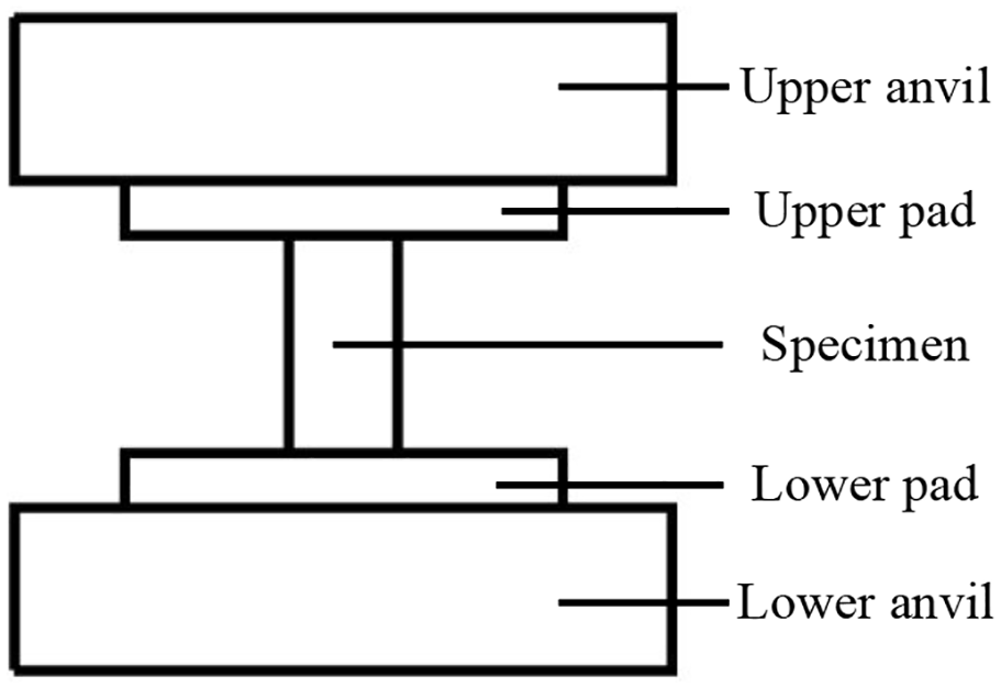
The diagram of the compression test. 13

Nonproportional compressive strength measurement results.
Elastic-plastic material parameters EP 2 are obtained by the following Hollomon’s equation14,15:

where
Elastic-plastic material parameters EP 3 are obtained by the Ramberg-Osgood equation4,16:

where E = 212 GPa,
Elastic material model E 1 is also considered in the study; the elastic modulus is 212 GPa, and the Poisson’s ratio is 0.3. 17
Overall finite element model of slewing bearings
A commercial 012-40-1000 single-row four-point contact ball slewing bearing is selected according to JB/T 2300-2011. 18 The basic structures are shown in Figure 4, and the geometric parameters are shown in Table 1.

Drawing and geometric parameters of the single-row four-contact ball slewing bearing.
Specific parameters of the single-row four-contact ball bearing.

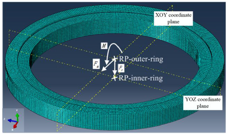
The finite element software used in the paper model is ABAQUS. The nonlinear spring is used to simulate the contact behaviour between the raceway and the balls, 19 as shown in Figure 5. The load-deformation characteristics of the spring and the rolling balls are the same. Hexahedral element and ‘sweep’ scan meshing are used. The meshing algorithm is the medial axis neutral axis algorithm. Hex unit type C3D8I is chosen as the element of the inner and outer rings. The surface contact part of the rolling ball is the main surface, and the contact part of the raceway is the slave surface in the contact between the rolling ball and the raceway. The inner ring surface is coupled to the reference point Rp-inner-ring. The outer ring surface is coupled to the Rp-outer ring, as shown in Figure 6. The Rp-inner-ring is constrained. The X-axis and Y-axis translational degrees of freedom and Z-axis rotation degrees of freedom of the Rp-outer ring are released. Other degrees freedoms are constrained. The load is applied to the Rp-outer-ring.

Nonlinear spring representing rolling balls: (a) schematic and (b) finite element model.
Loads applied to the slewing bearing.
Verification of the local finite element contact model of slewing bearings
A local finite element contact model is developed to simulate the contact between the rolling ball and the raceway. The following settings are made in the model to be able to use Hertz theory to validate the model: (1) the contact material is isotropic elastic; (2) there is no friction; and (3) the load direction is consistent with the initial contact angle. The local FEM is validated by the Hertz theory. The load direction in the FEM is changed to conform to Hertz theory, as shown in Figure 7.

Schematic diagram between the rolling ball and the raceway.
The maximum contact stress occurs at the geometric centre of the ellipse 20 as follows:

Two loads are applied in the model, and the results are shown in Table 2. The differences between the results of the Hertz theory and FEM are 6.84% and 5.27%, respectively, which are within a reasonable range. 21 Therefore, the results of the finite element contact model can be used in subsequent local slewing bearing models.
Comparison of the contact stress.

Analysis and discussion of the results
Overall model analysis
Many empirical formulas have evolved in the field of slewing bearings after long-term engineering practice. These formulas have been tested in practical engineering applications and have been largely applied. Equation (4) is suitable for a raceway with a zero-gap structure, 22 and equation (5) is suitable for slewing bearings that do not require strict cross-sectional clearance. 23


Three different load conditions are applied to the overall model (Figure 6), as listed in Table 3.
Load conditions in the overall finite element model.

The results of the maximum contact load are plotted in Figure 8. Material properties EP 1 are obtained through the compression test, and the results of EP 1 are considered as the baseline. The maximum contact load obtained by the FEM is substantially greater than that of the empirical formula, and the maximum error reaches 24.2% at load 1, while the error using equation (5) is less than that of equation (4). This shows that equation (5) is more suitable for the slewing bearings with gaps for this load condition regarding the maximum contact load. The contact angle changes when the slewing bearing is loaded. However, the contact angle maintains the initial value in equations (4) and (5), and this contributes to calculation errors.

Comparison of maximum contact loads of different models: (a) load 1, (b) load 2 and (c) load 3.
The elastic model and elastoplastic model result in the same maximum contact load at the small load (Load 1). The results of the maximum contact loads differ with different material settings with increasing load. The elastic material tends to result in a higher load than elastic-plastic materials, and the result of E 1 is 14.5% different from the baseline model at the highest load. The EP 3 model is the closest to the test results among the three elastic-plastic models, indicating that EP 3 can imitate the stress-strain curves of the material and can be used in modelling when no tested material properties are available.
The deformation comparisons of different models are shown in Figure 9. The results of the maximum contact load and the deformation of all the models are the same under small load conditions, indicating that only elastic deformation occurs. The differences between the models increase with increasing load as more plastic deformation occurs. The results of EP 3 match the best with the baseline model. It is also noted that the elastic material results in smaller deformations compared to EP materials, and the difference is as high as 12.9% at load 3, suggesting the importance of considering plastic deformation in the calculations.

Deformation comparisons of different models.
The comparisons of the calculation times of different models are shown in Figure 10. When the contact area is excessively plastically deformed, the calculation time of the elastoplastic material model is larger than that of the elastic material model under the same load conditions. The calculation time of the elastoplastic finite element model parameters will be very large. Therefore, a nonlinear spring structure instead of a ball is used to perform a full-circle deformation calculation, which will save considerable time and reduce the calculation difficulty.

Comparison of calculation time of different models.
The raceway load distribution consists of the contact load between each rolling element and the raceway inside the slewing bearing. When the local contact state between the rolling element and the raceway of the slewing bearing is analysed, the raceway load distribution provides the maximum contact load and its position. When the fatigue life of the slewing bearing raceway is studied, the raceway load distribution provides the contact load at any position for analysis and a basis for fatigue life in all areas of the raceway. The contact load distribution trends of the slewing bearings are the same at the small load, and the values and the trend are the same as shown in Figure 11. As the load increases, the contact load distribution becomes steeper, and the load value increases. The steeper the load distribution curve is, the smaller the number of balls that are subjected to large loads. The heavy-duty area ball is subjected to more loads, which will result in high stress in the area.

Slewing bearing load distribution diagram: (a) small load condition; (b) medium load condition and (c) large load condition.
Analysis of the local contact model results
The stress distribution is almost the same under the small load for all the material models, as shown in Figure 12. As the load increases, the equivalent stress values differ greatly, and the EP 3 material model is the closest to the test material EP 1 model. It is also noticed that the high stress area becomes larger with increasing load.

Local contact model stress: (1) small load condition, (2) medium load condition and (3) large load condition.
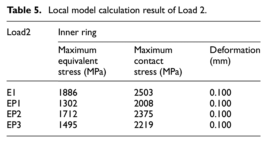
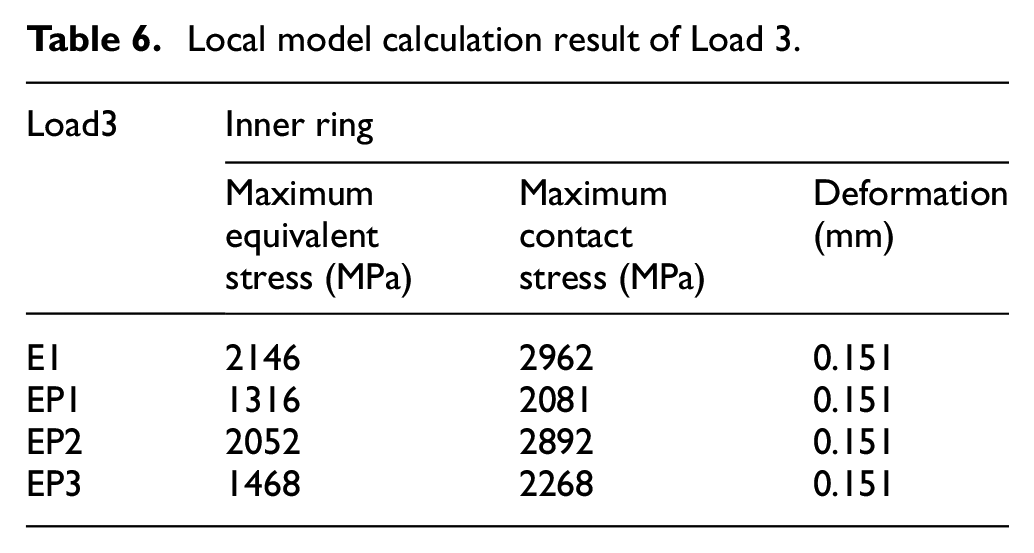
The equivalent stress, contact stress and deformation of the components in the local contact model of the slewing bearing are further listed in detail in Tables 4 to 6. All the values are the same under the small load. When the load is higher, the elastic model shows much greater equivalent stresses and contact stresses and a smaller deformation.
Local model calculation result of Load 1.

Local model calculation result of Load 2.
Local model calculation result of Load 3.
Conclusions
A local finite element model of the rolling ball and the raceway of a slewing bearing is developed and validated using Hertz contact theory. An overall model is established, in which the rolling ball is modelled as nonlinear springs.
Different elastic and elastic-plastic material models are considered in the model. It is shown that plastic deformation occurs at a higher load, indicating that elastic-plastic material properties must be considered in the model. Additionally, the maximum contact stress obtained by the elastic material model is substantially larger than that of the elastoplastic material parameter model, which yields unnecessary conservative results when calculating the safety factor and causes an unnecessarily heavy weight and large slewing bearings.
EP 3 matches best with the baseline model among all the elastic-plastic material models. When the test material properties are not available, the EP 3 model can be used to represent 42CrMo materials with different hardness. The research in this paper is beneficial for improving the calculation accuracy and reliability of the carrying capacity of a slewing bearing and to optimise the structure.
Footnotes
Appendix
Handling Editor: James Baldwin
Author contributions
All authors have contributed to the development of the research and in the elaboration of this paper. Particularly, Peiyu He, Yun Wang and Hong Liu contributed to the writing, the investigation and the simulation; Erkuo Guo and Hua Wang carried the experimental research and edited the manuscript. All authors have read and agreed to the published version of the manuscript.
Declaration of conflicting interests
The author(s) declared no potential conflicts of interest with respect to the research, authorship, and/or publication of this article.
Funding
The author(s) disclosed receipt of the following financial support for the research, authorship, and/or publication of this article: The authors gratefully acknowledge the support provided by the National Natural Science Foundation of China (No. 51575245 and 51679112), the Six Talent Peak Selection and Training Programme of Jiangsu (ZNYQC-002) and the China Postdoctoral Science Foundation (2020M671354).