
Abstract
Mechanical model with detailed design parameters of a rotor slewing bearing with the structure type of double-row tapered roller for supporting the rotor of the wind turbine was presented. The internal geometrical relationships of the rotor slewing bearing were established in the Cartesian coordinate system. The elastic contact deformations between each tapered roller and the raceways were expressed through the geometrical transformation. The mechanical model was established using the equilibrium relations in the rotor slewing bearing. The safety factor and the fatigue life which represents, respectively, the ability of resisting the rolling contact plastic deformation failure and the rolling contact fatigue failure of the rotor slewing bearing were obtained based on the solution of the mechanical model. Effects of the detailed design parameters such as axial clearance, contact angle, and roller semi-cone angle on the carrying capacity of the rotor slewing bearing were analyzed. The results show that right amount of small negative axial clearance, increase in contact angle, and decrease in roller semi-cone angle are advantageous for enhancing the carrying capacity of the rotor slewing bearing. This provides the basis for the reasonable value selection of the design parameters of the double-row tapered roller slewing bearing for supporting the rotor of the wind turbine.
Keywords
Introduction
In recent years, utilization of renewable energy represented by wind power by countries around the world reached a climax. The world wind capacity reached 435 GW by the end of 2015. 1 With the emergence of many kinds of faults of the grid connected wind turbines, reliability problem of the wind turbines becomes more and more prominent. Slewing bearings are one of the key components with the most expensive maintenance and replacement cost in the wind turbine, the reliability problem of slewing bearings used in wind turbines is becoming the focus of attention of researchers. The reasonable design of the rotor slewing bearing used in the wind turbine is based on the systemic mechanical analysis of the influencing law of the detailed design parameters on the carrying capacity.
At present, the research work of the slewing bearing used in the wind turbine mainly focused on the pitch slewing bearing or yaw slewing bearing which has the structure form of single-row or double-row four-point contact ball. Gao et al. 2 established the nonlinear equations of a single-row four-point contact ball slewing bearing, the sensitivity of some design parameters of the ball, and the raceways which influence the maximum ball load and the slewing bearing service life was discussed. Chen et al. 3 developed a mechanical model of a double-row four-point contact ball slewing bearing and studied the effects of the geometric parameters on the carrying capacity of the slewing bearing. Potočnik et al. 4 described the internal geometrical relationship of a double-row four-point contact ball slewing bearing with vectors and established the equilibriums of the slewing bearing. Calculation of the maximum ball load and the fatigue life of the bearing were performed. Glodež et al. 5 established a vector-based static equilibrium model of a double-row four-point contact ball slewing bearing, and the fatigue lifetime of the slewing bearing was calculated by stress-life approach and strain-life approach. Aguirrebeitia et al. 6 presented a static mechanical model of a single-row four-point contact ball slewing bearing under radial load, axial load, and tilting moment load. A carrying capability surface of the slewing bearing was calculated by solving the model. Wang and Yuan 7 established the static mechanical model of a double-row four-point contact ball slewing bearing in the polar coordinates and analyzed the effect of negative clearance on the load distribution of the balls. Daidié et al. 8 presented an analysis method of single-row four-point contact ball slewing bearing based on finite element analysis software, and the balls under compression were modeled by nonlinear traction springs between the curvature centers of the raceways. Olave et al. 9 proposed the calculation of the ball loads in a single-row four-point contact ball bearing considering the elasticity deformation of the supporting structure based on the finite element model (FEM) analysis and an elastic calculation procedure which considered the stiffness effect of the supporting structure. Gao et al. 10 calculated the load distribution of a single-row four-point contact ball bearing using FEM which simplified the balls to the springs. Chen and Wen 11 employed finite element analysis of the ball loads of the pitch slewing bearing of the wind turbine with the structure of double-row four-point contact ball and compared the results which considered the whole hub, the partial hub, and the rigid outer ring, respectively. Plaza et al. 12 studied the load distribution of the pitch slewing bearing of the wind turbine with the structure of single-row four-point contact ball and presented a FEM using the superelements, the model significantly reduced the computational time and nearly without accuracy loss.
Compared with the asynchronous doubly fed wind turbine, the direct-drive wind turbine eliminates the gear-speed increaser, and the rotor is connected directly to a permanent magnet generator, this offers significant advantage because the gear-speed increaser is more susceptible to fail, and only one slewing bearing is needed to support the rotor of this kind of wind turbine. The double-row tapered roller slewing bearing is deemed as a suitable selection to support the rotor of direct-drive wind turbine because the design of the double-row tapered roller slewing bearing is built around the concept of zero slip which minimizes wear over long periods of operation. Related research of mechanical calculation of double-row tapered roller slewing bearing has not been previously proposed.
In the traditional description of internal geometrical relationships of the slewing bearing, a polar coordinate system is set with its origin at the bearing center in the radial plane of the slewing bearing, and the polar angle describes the azimuthal angle of rolling element along the circumference. The Z-axis is in the bearing axis direction. Polar coordinates based method only uses two axes. In this article, the internal geometrical relationship of the double-row tapered roller slewing bearing for supporting the rotor of the wind turbine was described in Cartesian coordinate system. The Cartesian coordinates based method uses three axes to describe the internal geometrical relationships of the rotor slewing bearing, which is more advantageous than the polar coordinates based method which only uses two axes. The displacements of the raceway surface at the roller contact sites after the rotor slewing bearing being loaded were represented through geometrical transformation. The mechanical model including the detailed design parameters was established using the mechanical equilibrium relations in the rotor slewing bearing. Based on the solution of the mechanical model, two carrying capacity indicators, the safety factor and the fatigue life of the rotor slewing bearing, were calculated. The influencing law of the detailed design parameters on the carrying capacity was analyzed; this provides the basis for the reasonable value selection of detailed design parameters of double-row tapered roller slewing bearing for supporting the rotor of the wind turbine.
Mechanics modeling
The mechanical model of the double-row tapered roller slewing bearing was built based on the deformation compatibility conditions and the load equilibrium conditions.
Deformation compatibility conditions
The rotor slewing bearing is mainly composed of inner ring, outer ring, and two rows of tapered rollers. The outer ring is installed on the frame of the wind turbine, and the inner ring is joined with the rotor of the wind turbine. During the operation of the wind turbine, the aerodynamic loads acting on the rotor are passed to the frame through the rotor slewing bearing. The rotor slewing bearing sustains the radial load, axial load, and tilting moment load simultaneously.
For the convenience of the description of the internal geometrical relationships of the rotor slewing bearing, set up a Cartesian coordinate system in the center of the rotor slewing bearing, as shown in Figure 1. The coordinate system has its origin at the center of the rotor slewing bearing, the X-axis is vertically upward, the Z-axis is horizontal in the bearing axis direction, and the Y-axis is horizontally sideways so that X-axis, Y-axis, and Z-axis rotate clockwise.
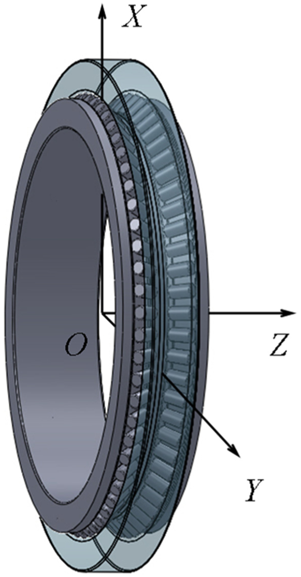
Coordinate system of the rotor slewing bearing.
In the axial section of the rotor slewing bearing, draw two dotted lines passing the centers of two tapered rollers and perpendicular to the center line of the tapered rollers, respectively. The dotted lines intersect with the raceway surface and produce the center points of the raceway width, that is,
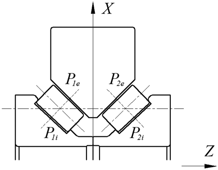
Center points of the raceway width.
Before the rotor slewing bearing being loaded, suppose that the tapered rollers are in the ideal position. That is at each roller position, gaps between each roller and raceways are same and equal to

Geometrical relationships in the XOZ coordinate plane.
In the XOY coordinate plane, positions of the center point
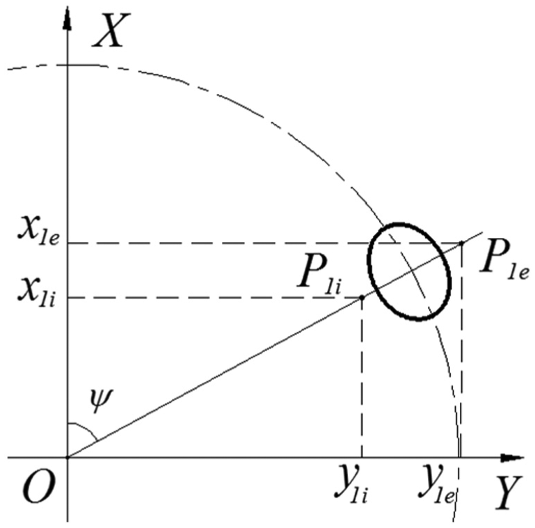
Geometrical relationships in the XOY coordinate plane.
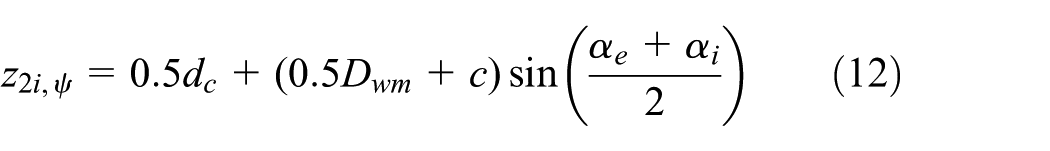
Use the geometrical relationship in the XOY coordinate plane and the XOZ coordinate plane, refer to Figures 3 and 4, the coordinate of each center point of each raceway can be described. At arbitrary roller azimuth angle


where
The coordinate of the center point


The coordinate of the center point


The coordinate of the center point


Before the rotor slewing bearing being loaded, the distances between the center points of the inner raceway and the outer raceway at the arbitrary roller azimuth angle


As the rotor slewing bearing being loaded, the outer ring is fixed in the wind turbine, and the inner ring produces the radial displacement

Inner ring displacements.
Thus, the positions of the centers of the inner ring raceway change correspondingly. According to the principle of geometrical transformation, the coordinate of the center point

Using the same geometrical transformation method, the coordinate
After the rotor slewing bearing being loaded, the distances between the center points of the inner raceway and the outer raceway at arbitrary roller azimuth angle


According to the geometrical relationship in Figure 3, the elastic contact deformations between the tapered roller and the raceways along


where
According the internal geometrical relationship of the rotor slewing bearing, the elastic contact deformations between the roller and the raceways along the normal direction of the outer raceway are


where
According to Hertz contact theory, the relationship between the roller load

where
Load equilibrium conditions
The entirety composed of the rollers and the inner ring of the rotor slewing bearing is at an balancing state under the external load
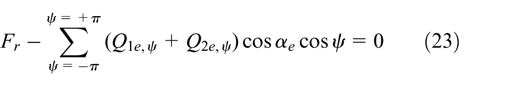


Equations (23)–(25) constitute a system of nonlinear equations with
Load analysis for the tapered roller
The tapered roller sustains three loads: they are the normal load from the inner raceway, the normal load from the outer raceway, and end surface load from the guide flange of the inner ring. Suppose the load between the roller and inner raceway, outer raceway, guide flange is
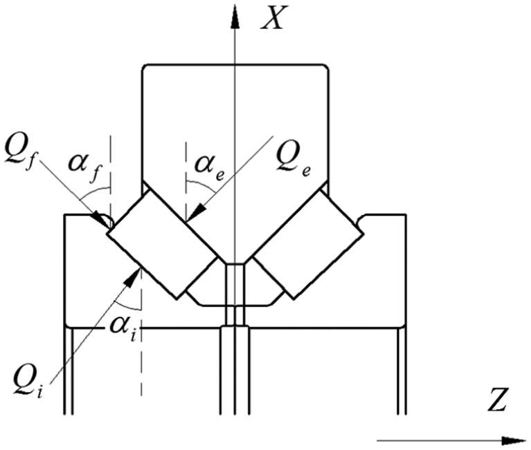
Loads of the tapered roller.
For static equilibrium, the sum of loads in the vertical direction and the horizontal direction is equal to zero, respectively, that is


In the above two equilibrium equations, the following can be obtained by eliminating

So load
Carrying capacity
Two carrying capacity indicators, that is the safety factor and the fatigue life which represents, respectively, the ability of resisting the rolling contact plastic deformation failure and the rolling contact fatigue failure of the slewing bearings are usually used as their design basis.
Safety factor
The rotor slewing bearing in the wind turbine sustains the action of impact loads during operation. Oversize impact loads will cause the permanent plastic deformation of the raceways at the contact sites between the tapered rollers and the raceways. This kind of deformation may affect the running performance of the rotor slewing bearings. According to the test results of Shen et al., 16 the maximum contact stress between the roller and the raceway surface of the slewing bearing made by the material of 42CrMo should be limited to 3300 MPa. This stress value is used as the allowable contact stress between the roller and the raceway. According to contact mechanics theory, the calculating formula of contact stress between the roller and the raceway is 14
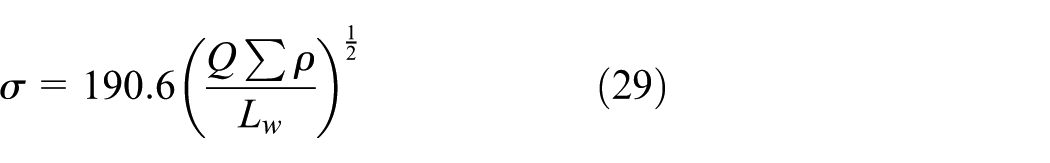
where
Consider the most loaded roller with the load
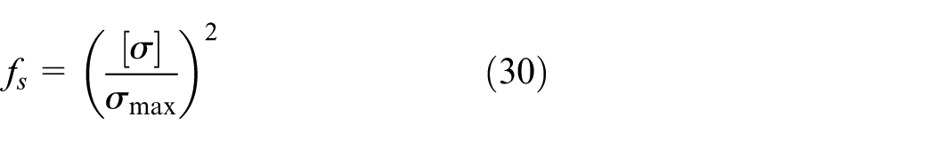
where
Fatigue life
The basic dynamic load ratings, dynamic equivalent roller loads, and roller load distributions are needed to calculate the fatigue life of the slewing bearing. The basic dynamic load ratings depend on the design parameters of the rotor slewing bearing, while the dynamic equivalent roller loads and the roller load distributions depend on the external loads carried by the slewing bearing. The basic dynamic load rating of the inner raceway and the outer raceway can be calculated using the design parameters of the slewing bearing. The dynamic equivalent roller load on the inner raceway and the outer raceway can be calculated using the calculated roller loads. The fatigue life of inner raceway of each row can be calculated by the following 14
where
The fatigue life of outer raceway of each row can be calculated by the following

where
Then, the fatigue life of the rotor slewing bearing is

Based on the calculated roller loads
Effect of the design parameters on the carrying capacity
The rolling between the tapered roller and the raceway of the tapered roller slewing bearings is zero slip. The precondition to achieve zero slip is that the generating lines of all tapered rollers and the raceway cones, and the bearing axis intersect with the same point. As designing the double-row tapered roller slewing bearings, design space dimensions (i.e. inside diameter, outside diameter, and width) are given first, detailed design parameters such as clearance (preloaded), contact angle, and roller semi-cone angle need to be determined.
The slewing bearing to be analyzed in this article is a rotor slewing bearing in certain type of 2.0 MW direct-drive wind turbine. During operation, the external loads of the rotor slewing bearing are calculated using bladed wind turbine simulation tool, 17 as shown in Table 1.
Working condition.

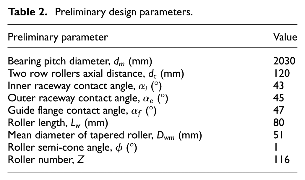
The given design space dimensions are as follows: the outside diameter is 2330 mm, the inside diameter is 1890 mm, and the width is 285 mm. According to these given dimensions, the preliminary design parameters of the rotor slewing bearing were determined as shown in Table 2. Based on these preliminary design parameters, select possible values of the detailed parameters such as clearance (preloaded), contact angle, and roller semi-cone angle that meet the zero slip design principle. The effect of these parameters on the safety factor and the fatigue life of the rotor slewing bearing were analyzed, so as to provide the basis for the reasonable value selection of these design parameters.
Preliminary design parameters.
Effect of the clearance
The effect of the axial clearance

Effect of clearance on the carrying capacity: (a) effect on the safety factor and (b) effect on the fatigue life.
As observed from Figure 7(b), as axial clearance increases from −0.0125 to 0.6, the fatigue life of the rotor slewing bearing decreases slowly. As the axial clearance decreases from −0.0125 to −0.4 toward the negative direction (preload increases), the fatigue life of the rotor slewing bearing decreases rapidly. Especially smaller the negative clearance is, more obvious this trend is. Maximum fatigue life appears as the axial clearance is near zero and slightly less than zero.
The effect of the axial clearance on the carrying capacity of the rotor slewing bearing can be attributed to the fact that increase or decrease in the clearance changes the roller load distribution. As the axial clearance increases, the rollers sustaining external loads become less and less, roller loads increase with it too, so the safety factor and the fatigue life decrease with it. From this perspective, smaller clearance is more advantageous to the rotor slewing bearing. As the axial clearance decreases toward the negative direction, the roller preloads increase with it, and the roller loads increase with it too, so the safety factor and the fatigue life decrease with it. From this perspective, bigger negative clearance is more disadvantageous to the rotor slewing bearing.
Effect of the contact angle
The effect of contact angle

Effect of contact angle on the carrying capacity: (a) effect on the safety factor and (b) effect on the fatigue life.
As observed from the results, effect trends of the contact angle change on the safety factor and the fatigue life of the rotor slewing bearing are roughly consistent. As the contact angle increases from 40° to 60°, the safety factor and the fatigue life of the rotor slewing bearing increase with it. The increase in the contact angle causes the component
Effect of the semi-cone angle
The effect of the semi-cone angle

Effect of semi-cone angle on the carrying capacity: (a) effect on the safety factor and (b) effect on the fatigue life.
Conclusion
In this article, the internal geometrical relationships of a rotor slewing bearing in wind turbine were described in Cartesian coordinate system; this is different from the traditional description of internal geometrical relationships of the slewing bearing in the polar coordinates. The geometrical relationships of all raceways are described as a unified form by this means; this makes the calculating model neater and more convenient for computer programming. Mechanical model with detailed design parameters was established using the equilibrium relations in the rotor slewing bearing. Effect laws of the detailed design parameters such as axial clearance, contact angle, and roller semi-cone angle on the carrying capacity of the rotor slewing bearing were analyzed.
As the axial clearance increases toward the positive direction, the safety factor and the fatigue life of the rotor slewing bearing decrease slowly. As the axial clearance decreases toward the negative direction (preload increases), the safety factor and the fatigue life of the rotor slewing bearing decrease rapidly. As the contact angle increases from 40° to 60°, the safety factor and the fatigue life of the slewing bearing increase with it. As the roller semi-cone angle increases from 50′ to 1°20′, the safety factor and the fatigue life of the slewing bearing decrease with it slowly. These results demonstrate that right amount of small negative axial clearance, increase in the contact angle, and decrease in the roller semi-cone angle are advantageous for enhancing the carrying capacity of rotor slewing bearing used in wind turbine.
Footnotes
Appendix 1
Academic Editor: David R Salgado
Declaration of conflicting interests
The author(s) declared no potential conflicts of interest with respect to the research, authorship, and/or publication of this article.
Funding
The author disclosed receipt of the following financial support for the research, authorship, and/or publication of this article: This project was supported by the National Natural Science Foundation of China (No. 51475144).