
Abstract
Slewing bearings are widely used in industry to provide rotary support and carry heavy load. The load-carrying capacity is one of the most important features of a slewing bearing, and needs to be calculated cautiously. This paper investigates the effect of mesh size on the finite element (FE) analysis of the carrying capacity of slewing bearings. A local finite element contact model of the slewing bearing is firstly established, and verified using Hertz contact theory. The optimal mesh size of finite element model under specified loads is determined by analyzing the maximum contact stress and the contact area. The overall FE model of the slewing bearing is established and strain tests were performed to verify the FE results. The effect of mesh size on the carrying capacity of the slewing bearing is investigated by analyzing the maximum contact load, deformation, and load distribution. This study of finite element mesh size verification provides an important guidance for the accuracy and efficiency of carrying capacity of slewing bearings.
Introduction
Slewing bearings are the core components of large-scale rotating equipment, which is mainly composed of rolling elements, rolling rings, and isolation blocks, and is used to support rotatory motion and transmit loads. One example of single-row four-point contact slewing bearings is shown in Figure 1. Slewing bearings are widely used in industry, including construction machinery, entertainment equipment, wind turbines, medical equipment, and communication equipment. The harsh working environment, high working frequency, heavy load (axial force, radial force, and overturning moment), and large structural size (the maximum diameter can be up to 40 mm) are the characteristics of the slewing bearing. The contact area between the rolling element and the raceway is small, and the contact stress is very high (maximum allowable contact stress 4200 MPa), and the raceway failure exceeds 98% of the total failure of the slewing bearing.1,2 Therefore, the carrying capacity of the slewing bearing needs to be investigated to improve the reliability and service life of the slewing bearing. This has also become the principle of the slewing bearing design, which is of great help to reduce the accident rate, casualties, and economic losses.
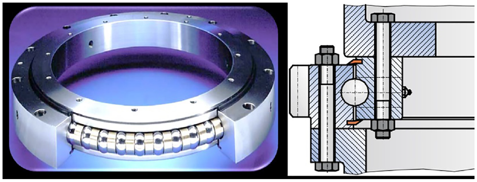
Single-row four-point contact slewing bearing. 3
Hertz contact theory is often used to calculate the local stress and strain distribution of the contact area, which is fast and the results are in line with the tests. 1 The maximum equivalent stress of the raceway is at a certain depth below the contact surface. The finite element modeling is thus a good alternative to solve the above problem. 4 Many scholars have analyzed the carrying capacity of slewing bearings using the finite element method, and it is found that the mesh size of the finite element model of the rolling ball and the raceway has great influence on the simulation results.5–7 Tian 8 developed a FE contact model of two rolling balls, and found that when the mesh size of the contact area was close to 50% of the short half axis of the contact ellipse, the calculation results were reliable. Satyanarayana and Melkote 9 also developed a ball and plate contact model, and the results show that the mesh size of the contact area needed to be less than 40% of the equivalent contact radius to obtain accurate contact deformation, and that the mesh size need to be not larger than 25% of the equivalent contact radius to make sure the contact pressure distribution is accurate. He et al. 10 investigated that mesh size of the contact area of slewing bearing, and the mesh size on the raceway was limited to 4–10 mm, and the ratio of the maximum to the minimum mesh size of the transition area is less than 4 to ensure the calculation convergence. Xin 11 investigated the mechanical properties of the rolling bearing using FE model, and concluded that the mesh size of the upper target surface should be about 1.5–2 times of the mesh size of the lower contact surface, and that the mesh size of the contact area should be five times smaller than the short semi-axis size of the contact ellipse. Many scholars used nonlinear structures (e.g. springs) to replace solid rolling bodies in the overall FE model of slewing bearing,12–14 which effectively solved the computational convergence problems.15,16 It should be noted that the mesh size of the overall FE model of slewing bearings has great influence on the calculation of the load distribution.
The rest of the paper is organized as follows: the second part described the finite element models. First FE model is a modified rolling ball and raceway FE model, which is developed to conform to Hertz theory, so that Hertz theory can be used to verify the model, the optimal mesh size is investigated. Second FE model is the contact model of real contact situation of rolling ball and raceway, in which the changing of contact angle during loading is included, and is called the local FE model of the slewing bearing; the effect of mesh size on the results of the maximum contact stress and the contact area is investigated; the third FE model is the overall model of slewing bearing in which elastic-plastic deformed spring is used to represent the local contact pair of rolling ball and raceway. The third part is about the experiments set up to measure the deformation and load distribution slewing bearing; the results and discussions are presented in part 4, and conclusion as part 5.
Finite element models
Hertz contact theory
The application of Hertz contact theory requires the following assumptions: (1) Elastic deformation occurs only in the contact area of the two objects and conforms to Hooke’s law; (2) The load is applied perpendicularly to the contact surface, and the friction between the contact objects is neglected. The contact surface and deformation formula between the rolling ball and the rolling ball can be derived from the Hertz contact theory 4 :
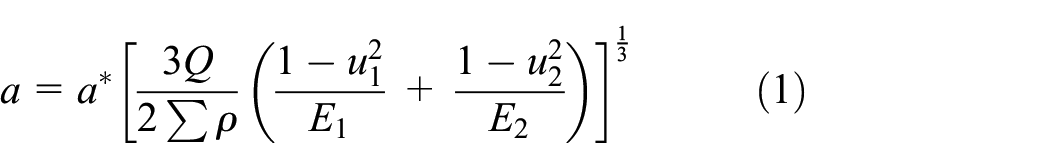


where
The maximum contact stress of the contact area between the balls appears in the geometric center of the ellipse, as:
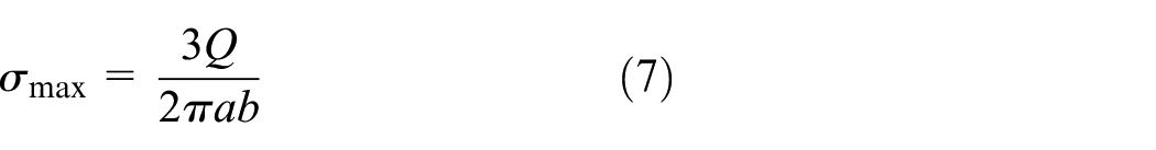
where
Local finite element contact models of slewing bearing
A single-row four-point contact ball type slewing bearing of 012-40-1000-10 (Referring to JB/T2300-2011 17 ) is selected and the structural dimensions are shown in Figure 2. The diameter of the ball is 40 mm, the number of the ball is 64, the diameter of the raceway is 1000 mm, and the initial contact angle is 45°.

Dimensions of single-row four-contact ball slewing bearing.
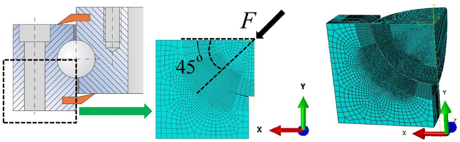
A local finite element model is developed to model the contact between the rolling ball and the raceway. To improve the calculation efficiency, only a quarter of the ball and raceway is modeled, as shown in Figure 3. The bottom surface of the raceway is fully constrained. The X-direction and Y-direction translation degrees of freedom of the ball is released, and other degrees of freedom are constraint. When the slewing bearing is loaded in actual working conditions, the rolling ball moves toward the edge of the raceway. The contact angle changes and the load on the rolling ball are not perpendicular to the raceway, which does not satisfy the assumption of Hertz contact theory. To be able to use Hertz theory to verify the local contact model, the same load as the initial contact angle (45°) is applied to the ball to ensure that the ball and the raceway are always in vertical contact, as shown in Figure 3. This model satisfies Hertz theory, and is called the verifying model (to distinguish from the real contact model that will be discussed later). The finite element software is ABAQUS. The verifying model is used to investigate the mesh size of the local finite element contact model of the slewing bearing. Hexahedral element C3D8I is assigned to mesh the 3D model. The meshing technology is Sweep mesh. The meshing algorithm is Medial Axis. The contact type is surface-to-surface contact, the surface of the rolling ball is the main contact surface, and the surface of the raceway is the contact slave surface. The materials of the ball and raceway are set the same, with the elastic modulus of 207 GPa and Poisson’s ratio of 0.3. According to the load capacity curve of the slewing bearings (based on the standards JB/T2300-2011), the load 2828 and 28,280 N are applied to the local verifying model. The maximum contact stress on the raceway surface calculated by the Hertz contact theory is 1195 and 2575.2 MPa, and the short half-axis length of the contact area is 0.3931 and 0.8469 mm, respectively. The mesh size from large to small is set from 1.5 to 0.15 mm 8 to investigate the effect of the mesh size on the accuracy of calculations.
Local contact model of ball and raceway of slewing bearing.
In actual working conditions, the load between the ball and the raceway in the slewing bearing is like in Figure 4 (left), and the verifying model is modified to adopt the real working conditions, as shown in Figure 4 (right). The load and boundary conditions are changed, and the load of Y direction is applied. The degree of freedom of translation in the Y-axis direction is released from the ball, while other degrees of freedom are constrained. The freedoms of the raceway bottom are constrained.

Local contact finite element model of slewing bearing.
Overall finite element model of slewing bearing
The nonlinear spring is used to simulate the contact behavior between the raceway and the ball of the slewing bearing, as shown in Figure 5(a). The load-deformation of the ball and raceway can be described as 4 :

where

Overall finite element models of slewing bearing: (a) nonlinear spring to represent the ball and (b) nonlinear springs in the slewing bearing.
To improve the calculation efficiency, ½ of the bearing is modeled in the finite element model. As shown in Figure 5(b), the reference points Rp-inner-ring and Rp-outer-ring are set in the geometric center of the inner and outer rings. The upper surface of the inner ring is kinematic coupling with the Rp-inner-ring. A fully fixed constraint is applied to the Rp-inner-ring. The lower surface of the outer ring is kinematic coupling with the Rp-outer-ring. The Rp-outer-ring releases the X-direction and Y-direction translational degrees of freedom and the Z-direction rotation degrees of freedom, constraining other degrees of freedom. According to the carrying capacity of single-row four-point contact ball slewing bearing, 17 an axial force of 79.1 kN and overturning moment of 200 kN·m to the reference Rp-outer-ring are applied to the model.
Experimental setup
The experiment of the single-row four-point contact ball slewing bearing (type 012-40-1000-10) was carried out on a slewing bearing test bench, as shown in Figure 6(a). Sixty-nine strain gauges are evenly attached along the inner side of the circumference and located in the middle area inside the inner ring, to measure the deformation of the slewing bearing indirectly, as shown in Figure 6(b) and (c). The deformation direction of the strain gauges is consistent with the axial direction of the slewing bearing, and temperature compensation is performed during the measurement. An axial force and an overturning moment are applied to the bearing by controlling the output pressure of the hydraulic cylinders M1and M2.

Test devices: (a) slewing bearing test apparatus, (b) layout diagram of strain gauge measuring points, and (c) actual layout diagram of strain gauge measuring points.
Results and discussions
Results of local finite element verification model
Figure 7(a) and (b) show the contact stress contours of the raceway between the ball and the raceway. It is found that: (1) The contact stress values of the raceway surface are different in the finite element model with different mesh sizes, and the values error is large; (2) As the mesh becomes smaller, the contact area of the contact stress contours becomes smoother. The transition region has no abrupt change, and the contact area is similar to an elliptical shape, which is consistent with the Hertz contact theory. Figure 7(c) and (d) are the equivalent stress contours of the local contact model of the slewing bearing. When the finite element mesh size is large, the maximum equivalent stress is on the raceway surface and not below the contact area, which is inconsistent with the actual situation and cannot be used in subsequent analysis.

Stress contours: (a) contact stress contours of mesh size 1.5 mm, (b) contact stress contours of mesh size 0.15 mm, (c) equivalent stress contours of mesh size 1.5 mm, and (d) equivalent stress contours of mesh size 0.15 mm.
Figure 8(a) shows the large mesh size on the contact area. The rolling ball and the raceway contact area interferes in the red marked area, and the mesh of the rolling ball is inserted into the raceway, which is not a smooth contact of the solid model and the error is large. In this case, the contact area between the ball and the raceway becomes small and causes local stress concentration. When the finite element mesh size is small, the contact area between the ball and the raceway is smooth, as shown in Figure 8(b).

Mesh diagram of the local finite element model of the slewing bearing: (a) mesh size 3 mm and (b) mesh size 0.1 mm.
An optimal mesh size of a contact model can be effectively determined by comparing the results of the stress contours, the maximum contact stress, and the contact area to Hertz theory. Figure 9 shows the comparison between the Hertz theory and the simulation results using different mesh size, where Figure 9(a) and (c) are the results under load 2828 N, and Figure 9(b) and (d) are the results under load 28,280 N. When the finite element mesh size is smaller than 50% of the short semi-axis length calculated by Hertz contact theory, the errors of the maximum contact stress and the contact area become stable, and the errors are within the acceptable range and can be used for subsequent carrying capacity analysis. 18 The mesh number of different meshing size is listed in Table 1. As discussed above, half of the short semi-axis length of the contact area was selected as the mesh size in the following finite element simulations. The mesh size at load 2828 N is chosen as 0.2 mm and the mesh size at load 28,280 N is chosen as 0.4 mm.

Comparison between the Hertz contact theory and finite element: (a) maximum contact stress and error of load 2828 N, (b) maximum contact stress and error of load 28,280 N, (c) contact area and error of load 2828 N, and (d) contact area and error of load 28,280 N.
Mesh number of finite element model.

Results and discussions of local finite element model
The finite element models are shown in Figure 4. Based on the analysis in Section 3.1, the model of mesh size 0.2 mm is selected as a reference for the load of 2828 N, and the model of mesh size 0.4 mm is for the load of 28,280 N. The comparisons between models of different mesh size are shown in Figure 10. It is shown that the simulation results are close to that of the reference model, and the deviations are small, thus, the mesh size smaller than 50% of the short semi-axis length calculated by Hertz contact theory can provide accurate simulation results.

Local finite element model results: (a) equivalent stress of load 2828 N, (b) equivalent stress of load 28,280 N, (c) maximum contact stress of load 2828 N, (d) maximum contact stress of load 28,280 N, (e) contact area of load 2828 N, and (f) contact area of load 28,280 N.
One of the important parameters affecting the bearing performance of the slewing bearing is the contact angle. Figure 11 shows the contact angle in the local contact finite element model of a slewing bearing with a load of 2828 N. The contact angle is 45°, which is the same as the initial contact angle. The small load does not cause the ball to move toward the edge of the raceway, so no changes are observed in the contact angle.
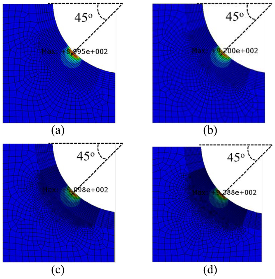
Contact angle of local finite element contact model of slewing bearing with load of 2828 N: (a) mesh size 0.4 mm, (b) mesh size 0.3 mm, (c) mesh size 0.2 mm, and (d) mesh size 0.15 mm.
As the load increases, the contact angle of the local contact model of the slewing bearing becomes larger, as shown in Figure 12. The maximum equivalent stress and the contact angle varies slightly, which shows that the finite element mesh size affects the value and position of the equivalent stress. As the contact angle increases, the assumption of the Hertz contact theory of the load acting perpendicular to the raceway is not satisfied, and the theoretical solution obtained by the Hertz contact theory cannot be used for comparative analysis. If the load is continuously increased, the contact angle continues to increase.

Contact angle of contact finite element local model of slewing bearing with load of 28,280 N: (a) mesh size 0.4 mm, (b) mesh size 0.3 mm, (c) mesh size 0.2 mm, and (d) mesh size 0.15 mm.
Results of overall finite element model of slewing bearing
Comparison with the finite element model of slewing bearing nonlinear spring
The mesh size of the finite element model of the slewing bearing is from 1 to 6 mm (MS 1-MS 6), and the load distribution results are shown in Figure 13. It is shown that the load distributions of the slewing bearings of different mesh sizes are quite similar, thus the mesh size has little effect on the load distribution of the slewing bearing.

Full-circle load distribution of the slewing bearing: (a) load on spring 1 and (b) load on spring 2.
Figure 14 shows the overall deformation of the slewing bearing with different mesh sizes. The maximum deformation of slewing bearing is located at the maximum coupling of the axial force and the overturning moment. As the mesh size becomes smaller, the overall deformation of the slewing bearing becomes larger. As the inner ring of the FE model is fixed and the loads are applied in the outer ring, large deformation occurs in the outer ring.

Overall deformation of slewing bearings of different mesh sizes: (a) MS 6 mm, (b) MS 5 mm, (c) MS 4 mm, (d) MS 3 mm, (e) MS 2 mm, and (f) MS 1 mm.
Comparison with the experimental results
The deformation of the finite element model corresponding to the position of the strain gauge is extracted, and plotted together with test results, as shown in Figure 15. The simulation results are quite close to each other except for the mesh size smaller than 5 mm, and the test results and the finite element calculation result show the same trend. The test results show large fluctuation at small deformation regions (strain gauge numbers 1–20 and 60–69), but they show a good match at the large deformation regions. The load distribution will be affected by the unevenness of the installation foundation surface, bolt pre-tightening force, and other factors in actual working conditions. Therefore, the load distribution obtained in the experiment will be different from the theoretical analysis result, but the change trend of the load distribution of the heavy load distribution are relatively consistent, which can also prove the reliability of the finite element analysis result. When the mesh is refined to a certain extent, the deformation of the slewing bearing is deformed equally under the selected load and structural dimensions.

Comparison of deformation results between the finite element model and strain test.
Comparison with the empirical formulas
After long-term engineering practice, many empirical formulas have been developed to calculate the carrying capacity of slewing bearings, one of formulas is equation (9), 10 which is suitable for the slewing bearing with no strict requirement for the cross-sectional clearance.

where
The simulated maximum contact load is compared with the results calculated using equation (7), and the results are shown in Figure 16. As the mesh size of finite element model of the slewing bearing becomes smaller, the difference and errors between the simulated results and that using equation (7) becomes smaller, and difference of the mesh size of 1 mm is only 4.56%.

Comparison of maximum contact load of slewing bearing.
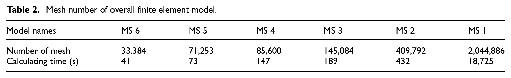
Table 2 shows the mesh number using different mesh size. Huge number of meshes will cause the simulation very time-consuming. Therefore, it is of great significance to select the optimal mesh size to reduce the calculation time while ensuring the accuracy of simulations. By comparing the experimental results and that of the empirical formulas, the mesh size 1 mm in overall model can provide the accepted simulation results.
Mesh number of overall finite element model.
Conclusions
The influence of the mesh size on the finite element local and overall model of the slewing bearing is studied in this paper. The local finite element contact model is compared and verified with Hertz contact theory. The results of overall finite element model are compared with the strain test. The effect of mesh size in local and overall finite element models are investigated by comparing the results of equivalent stress, contact stress, contact area, load distribution, full circle deformation, etc. The conclusions are as follows:
When the mesh is too big in the local finite element contact model, the contours of the contact area between the rolling ball and the raceway are not smooth, and discontinuous occurs in the contact area, resulting in a decrease in the contact area, causing local stress concentration.
Mesh size affects the value and position of the maximum equivalent stress. The mesh size needs to be smaller than 50% of the short semi-axis length calculated by Hertz contact theory to obtain acceptable results. Also, the contact angle changes obviously under high load conditions, and the mesh size needs to be small enough to capture the contact angle accurately.
In the overall FE model of the slewing bearing, the mesh size is ranged from 6 to 1 mm. The trends of the load distribution of the inner ring are not influenced by the mesh size; however, the deformation of the outer ring increases with the mesh size becoming smaller.
The paper provides an important guidance for the slewing bearing designers to calculate the carrying capacity and structural design optimization.
Footnotes
Appendix
Handling Editor: James Baldwin
Author contributions
All authors have contributed to the development of the research and in the elaboration of this paper. Particularly, Peiyu He, Qinrong Qian, Yun Wang, and Hong Liu contributed to the writing, the investigation, and the simulation; Erkuo Guo and Hua Wang carried the experimental research and edited the manuscript. All authors have read and agreed to the published version of the manuscript.
Declaration of conflicting interests
The author(s) declared no potential conflicts of interest with respect to the research, authorship, and/or publication of this article.
Funding
The author(s) disclosed receipt of the following financial support for the research, authorship, and/or publication of this article: The authors gratefully acknowledge the support provided by the National Natural Science Foundation of China (nos. 51575245 and 51679112), the Six Talent Peak Selection and Training Program of Jiangsu (ZNYQC-002), the China Postdoctoral Science Foundation (2020M671354), and the Postgraduate Research & Practice Innovation Program of Jiangsu Province (KYCX20_1062).