
Abstract
The brake disc plays a crucial role to keep the stable braking of a high-speed and heavy-duty disc brake. There is always high temperature, brake vibration, and even serious deformation under braking pressure and frictional resistance. To improve brake performance, this paper aims to find new internal and surface structures of the brake disc. An equivalent moving load (EML) topology optimization method for internal structure is proposed. Topography optimization method oriented to displacement and stress control for surface structure is carried out. Multiobjective functions containing thermal-structural coupled rigidity and natural frequency of the brake disc are established in the internal and surface structure optimizations. Internal and surface structures of the brake disc are optimized, and the mechanic properties of the brake disc are improved. Thermal-structural coupling and modal analyses are verified with high-speed and heavy-duty brake working conditions. The results show that new brake disc structures meet the requirements, and the effectiveness of the proposed EML topology optimization and topography optimization methods has been proved.
Keywords
Introduction
High-speed and heavy-duty disc brakes are widely used in many fields, such as high-speed railway vehicles and large-megawatt wind turbines. Figure 1 shows the high-speed and heavy-duty disc brake used in a 2 MW wind turbine. The brake disc is an important component of the high-speed and heavy-duty disc brake. During braking, the brake disc-pad contact produces a lot of heat under the action of braking pressure and frictional resistance. Abrasion of the brake disc is one of the most common faults in the brake system. 1 Uneven contact of the brake disc-pad leads to a discontinuous contact area. It affects the brake displacement, the surface temperature, the contact stress, even the brake shaking and chattering directly. Therefore, the high-speed and heavy-duty braking process is a friction-heat-vibration coupling phenomenon. 2
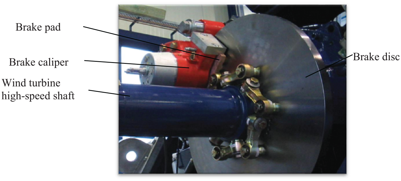
High-speed and heavy-duty brake disc used in a 2 MW wind turbine.
The friction-heat-vibration coupling phenomenon and the resulting issues have become key points of the disc brake study. In the temperature and thermal stress field, Goo 3 measured the contact pressure of the brake disc-pad to understand the tribological characteristics of a frictional brake system. Wang et al. 4 investigated the temperature evolution of the railway vehicle brake disc during high-speed braking by using in situ experiments, theoretical analysis, and finite element modeling. The results showed that it was the corresponding fluctuation of instantaneous frictional coefficient and thermal stress distribution caused by the temperature variation that resulted in the thermal damages. Sawczuk 5 found that the coefficient of friction decreases upon the wear of both the brake pad and the brake disc. Chen and Kienhöfer 6 analyzed that the mechanical stresses developed by the brake disc were characterized in terms of compressive stresses due to the clamping load as well as the shear stresses due to the applied braking torque. Furthermore, Gigan et al. 7 studied the thermal-mechanical behavior of the brake disc in heavy vehicles and established the fatigue life model to calibrate the thermal-mechanical fatigue life. Hong et al.8,9 used an infrared camera to analyze the thermal behavior of the brake disc in high-speed railway vehicles, and the causes of the hot band and hot spot were suggested. Waddad et al. 10 presented a multi-scale strategy for the thermal-mechanical simulation of frictional systems. With the established model, the influence of the interface behavior and wear on the system response was clearly shown. The above research showed the universality of the problems caused by high temperature and thermal stress in the high-speed and heavy-duty brake working conditions. Improving the temperature and thermal stress distribution is an urgent problem to be solved. An important issue in brakes is temperature changes, which in extreme cases generate hot-bands or hot-spots, Li et al. 11 carried out full-scale emergency braking tests. The tests results showed that the cyclic thermal and mechanical loads cause high temperature, plastic strain, and even phase change of the brake disc steel. Meanwhile, the occurrence of variable stresses causes fatigue cracks, Wang et al. 12 analyzed the sequential thermal and mechanical stress that affected crack propagation and microstructure evolution in the brake disc, and simulated braking cycles on a full-scale braking bench test rig.
In the field of braking vibration and noise, De Simone et al. 13 presented the results of an experimental investigation on squeal noise emitted by a disc brake for railway applications, which proved the existence of the brake vibration and screaming. Cascetta et al. 14 developed a numerical model for squeal frequency prediction of railway disc brake based on the finite element theory. Tang et al. 15 developed a bespoke small-scale brake dynamometer to simulate the braking conditions of a railway disc brake system. They investigated that higher rotation speeds were found to result in higher sound pressures. Chen et al. 16 carried out a field test measurement and a finite element analysis of disc brake squeal to suppress or eliminate brake squeal of light rail trains. The existence of brake vibration and its influence on the braking process was verified by experiment and simulation analysis. Important issues in brakes are vibrations and noise, which harm braking performance, Cabboi and Woodhouse 17 presented a first qualitative attempt to predict squeal events utilizing rate-and-state models based on the identified model parameters and shown to give promising correlation with experimental results. Sawczuk et al. 18 presented the relation between vibroacoustic signals of the right and left friction pad during braking depending on the mass distribution of the lever system component.
It is also worth quoting the works of researchers on the use of other materials for shields. The widely used brake disc material is cast iron which consumes much energy due to its high specific gravity during braking. Crăciun and Pinca-Bretotean 19 developed a new natural fiber reinforced aluminum composite for the brake disc. By modeling appropriate matrix and reinforcement volume percentages, low-density and high-hardness characteristics of materials can be obtained. Li et al. 20 discussed the research status and development trends of ceramics for automotive disc-brakes. According to the ceramic disc-brakes, various properties and characteristics, including fracture toughness, strength, compactness, corrosion resistance, wear resistance, micro-morphology, and thermal stabilities are analyzed. Yevtushenko et al. 21 determined the temperature fields in the coating and the disc a one-dimensional friction heat problem during braking was formulated, taking into account the dependence of thermal properties of materials from temperature. Strojny-Nędza et al. 22 presented the developed method of manufacturing dense copper–alumina FGMs, using ceramic preform with a graded porosity infiltrated with molten copper, to obtain a material with high resistance to friction wear as well as good dissipation of heat generated. Varecha et al. 23 focused on the investigation of tribological and thermodynamic parameters of the coated C45 steel substrate. The simulation of the non-stationary heat conduction process in the brake system revealed that the most suitable thickness of the steel brake disc should be at least 8.2 mm. This research would help the designer to choose the right procedures for designing a multidisc brake system.
Based on the above research, many scholars have researched the structure optimization of the brake disc to improve the effect of temperature and vibration. Zhou et al. 24 proposed a non-dominated sorting genetic algorithm-analytic hierarchy process (NSGA-AHP) method for the multiobjective optimization in a disc brake. Labdi and Bouchetara 25 developed a thermal and mechanical study of an aeronautical brake disc, in which they had made geometric changes. It is also worth mentioning the research on drilled discs, Yan et al. 26 used numerical simulations to carry out a systematic comparison of the thermo-fluidic characteristics between standard and cross-drilled ventilated brake discs incorporating radial vanes. Mechanisms for heat transfer enhancement by the cross-drilled holes are clarified. Besides, some studies had shown that specific surface structures can improve the brake performance of the brake disc, such as providing a stable friction coefficient and avoiding brake vibration and screaming. Kim et al. 27 optimized the tie-bar shape and the groove shape around the disc hub by FE-based shape optimization to reduce squealing. Lu et al. 28 designed several parallel grooves structures on damping components, and experiments were performed using a purpose-built experimental test bench. The results showed that the parallel-grooved structure could effectively suppress the friction-induced vibrations, and improve the wear characteristics. Zhang et al. 29 designed a different-angled grooved structure, and the grooved structure was manufactured on the damping components. The results showed that the grooved-structure brake disc exhibited a lower vibration amplitude. Sayeed Ahmed and Algarni 30 analyzed the effect of design modification with radial grooves on disc brake performance and its thermal behavior by using additive manufacturing. They also decided on the design modification and the number of radial grooves based on existing dimensions.
However, the surface structures designed above are all designed artificially. It is still not clear that what kind of surface structure can be used on the high-speed and heavy-duty brake disc to maintain the stable braking process. In addition, the brake performance of the brake disc with both internal and surface structure also should be analyzed. Therefore, the structural design for the braking performance of high-speed and heavy-duty brake discs is very important. This paper starts from the design of the brake disc structure for performance improvement and obtains the mechanical performance of the unoptimized brake disc by analyzing the performance of the brake disc under high-speed and heavy-load braking conditions (thermal structure coupling analysis and modal analysis). The requirements that the brake disc needs to meet after being optimized. This paper proposes two methods to optimize the internal structure and the surface structure, respectively. In both of the two methods, it is considered for improving the rigidity and avoiding the brake vibration under the thermal-structural coupling working condition. Finally, to verify whether the performance of the optimized brake disc structure meets the requirements, the braking performance comparison including thermal structure coupling analysis and modal analysis is carried out. The reliability of the proposed method can also be verified through data comparison. The overall flow chart of the entire study in this paper is shown in Figure 2.

Overall flow chart of the entire study in this paper.
Mechanic property analysis of high-speed and heavy-duty brake disc
Thermal-structural coupling analysis
Disc brakes have a complex structure, and the braking process requires the cooperation of many components to complete. Taking the large-megawatt wind turbine brake shown in Figure 1 as an example, the thermal-structural coupling of the high-speed and heavy-duty brake disc is studied.
Assumptions
There are many components in high-speed and heavy-duty brake discs, such as brake calipers, hydraulic cylinders, etc., to accelerate the convergence of the simulation, the model of the high-speed and heavy-duty brake disc needs to be simplified before the thermal-structural coupling analysis. It is simplified into a model of the brake disc and the brake pad, and the effects of other components on the brake disc and the brake pad are loaded into the model in the form of various constraints, to simulate the real braking conditions. Some basic assumptions are claimed as follows:
Both materials are considered isotropic, and the sliding friction coefficient between them is constant during the sliding process. All the material property parameters do not change with the temperature change.
The contact surface of the brake disc and the brake pad is an ideal flat plane.
During the braking process, all the kinetic energy is converted into heat, and the thermal simulation is performed dynamically.
Brake pads are fixed on every side of the brake disc, so the force and heat conditions on both sides are the same. The brake disc-pad is symmetric along the mid-plane. The brake disc in this article is cut into two parts along the mid-plane of thickness direction, and there is only one brake pad and half of the brake disc.
The thermal stress effect in the calculations is considered, and the thermoelastic instability phenomenon during a single braking process is ignored. Furthermore, the effects of wear and fatigue are not considered.
The braking process of disc brake is a typical thermal-mechanical coupling problem and the effects of heat and force are mutually interrelated. To analyze the simultaneous solution of mechanical and thermal problems, a strong coupling method is used for calculation.
Methodology of the thermal structural coupled analysis
Distribution of heat-flow density
According to the law of energy conservation and the principle of frictional heat generation, that is:

where Q is the friction heat, W is the friction work, Ff is the friction, s is the friction distance, μ is the coefficient, F is the braking pressure, v(t) is the braking speed, and te is the braking time.
According to the heat flow calculation equation, the total heat-flow density generated by the brake disc and the brake pad during the braking friction process is calculated, that is:
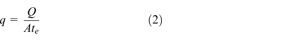
where, q is the heat-flow density, and A is the contact area. The generated total heat flow will be distributed by the brake disc and the brake pad in a proportional equation. The equation for calculating the proportional coefficient is:

where r is the heat-flow density distribution ratio, qd and qp are the heat-flow, kd and kp are the thermal conductivity, Cd and Cp are the specific heat capacity, and ρd and ρp are the density.
Heat conduction
Combining natural heat conduction and friction heat-flow formulas, the heat conduction equations of brake discs and brake pads can be obtained:

where kc is the thermal conductivity between the brake disc and the brake pad. Td and Tp are the transient temperatures. On the contact interface between the brake disc and the brake pad, the transient temperature of each node is correspondingly equal, and the heat-flow density is calculated between the brake disc and the brake pad according to the respective material properties and distributed ratio, which can be obtained Td = Tp. The transient temperature of the contact interface between the brake disc and the brake pad is equal. Therefore, equation (4) can be expressed as:

According to the above derivation of the natural heat conduction and friction heat-flow density between the brake disc and the brake pad, the temperature rise equation of the brake disc can be obtained, that is:

where, ωt is the weight coefficient of the heat-flow density, p(x,y,t) is the specific pressure, p(x,y,t) is the relative speed, and T0 is the environment temperature.
Calculation of thermal stress
When performing topology optimization analysis of a structure under the action of a thermal structure coupled field, it is necessary to obtain the equivalent stress and equivalent strain. Therefore, the calculation of thermal stress is deduced below:

where, [σ] is the thermal stress of the brake disc, [D] is the elastic stain matrix of the brake disc, [ε] is the strain matrix, [Δε] is the temperature strain matrix. In the three-dimensional space, the temperature strain caused by the temperature change of the friction material of the brake disc can be expressed in terms of temperature rise, that is:

where αt is the coefficient of thermal expansion. Based on the above equations:

The thermal stress generated by the brake disc along the thickness direction is:

where σz is the thermal stress of the brake disc.
Calculation of contact pressure
The contact pressure between the brake disc and the brake pad is generated by the oil pressure generated by the hydraulic cylinder.

where P is the contact pressure between the brake disc and the brake pad, P1 is the oil pressure, d1 is the diameter of the brake cylinder piston.
Establishment of the finite element model
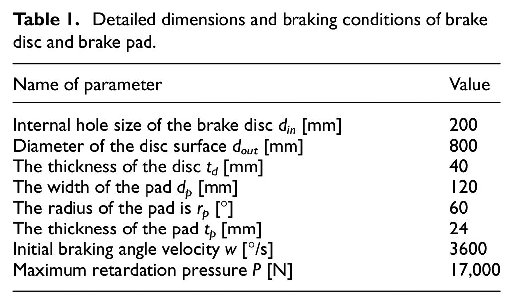
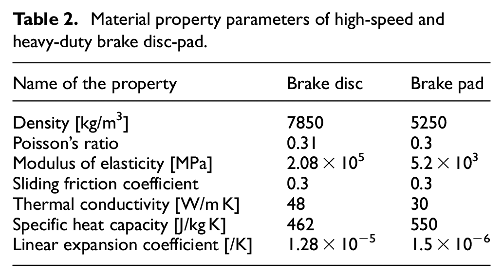
Based on the assumptions, the finite element model of the large-megawatt wind turbine brake disc-pad is established by using the Abaqus software. In this paper, the temperature-displacement coupling C3D8RT type element is adopted, because C3D8RT has the advantage of the thermal structural coupled simulation calculation, including 8-node thermally coupled brick, trilinear displacement, and temperature, reduced integration, and hourglass control. The hexahedral mesh is used, which could make the solution efficient and the convergence is well. The entire brake is divided into a total of 7995 grids. According to the actual working conditions of the disc brake, the brake disc rotates with the high-speed shaft during braking, the brake pad is fixed on the caliper body. The upper surface of the brake pad is pressed, and the brake pad is pressed against the brake disc for contact friction. Since the brake disc has a symmetrical structure, only one side is studied, and the bottom surface of the brake disc is symmetrically restricted. The brake pad is fixed, and the surface load of the upper surface of the brake pad is set in the z-direction to limit the displacement of the brake pads in the x and y directions. To control the speed of the brake disc, a rigid point RP point is set in the center of the brake disc, the inner ring of the brake disc is set as a rigid area. Set the RP point to have the initial speed, which can only rotate around the z-axis, and restrict the x and y-axis rotation of the brake disc. The restraint of the brake disc and brake pads is shown in Figure 3, and detailed dimensions and braking conditions of brake discs are shown in Table 1. The material of the brake disc is E355CC, which has the advantages of mechanical properties, including high toughness, strong compressive and tensile capabilities, and well plasticity and welding properties. 31 Meanwhile, the material of the brake pad is F1101H, which has high plasticity and toughness, corrosion resistance, and stable friction coefficient. 32 Material property parameters of high-speed and heavy-duty brake disc-pad are shown in Table 2.
Detailed dimensions and braking conditions of brake disc and brake pad.

Thermal-structural coupling analysis finite element model of brake disc and brake pad.
Material property parameters of high-speed and heavy-duty brake disc-pad.
Results of thermal-structural coupling analysis
With the Abaqus software, the thermal-structural coupling analysis is completed. After 19.16 s, the braking process is over. Result contours of the brake displacement, the surface temperature, and the equivalent stress after thermal-structural coupling analysis are shown in Figure 4.

Result contours of thermal-structural coupling analysis: (a) brake displacement, (b) surface temperature, and (c) equivalent stress.
Figure 4(a) is the displacement contour of the brake disc surface. The displacement value increases from the inner side to the outer side of the brake disc. The maximum displacement of the brake disc is 0.8003 mm. Figure 4(b) and (c) show the surface temperature and equivalent stress, respectively. Both the maximum value of the surface temperature and the equivalent stress appears at the contact area of the brake disc and the brake pad. The maximum temperature is 662.3°C, and the maximum equivalent stress is 359.1 MPa. The maximum value appears at 13.14 s.
Modal analysis
The basic theory of modal analysis is to list the dynamic balance equation of the structure as a whole, that is:

where, [M] is the mass matrix, [C] is the damping matrix; [K] is the stiffness matrix,

Substituting into equation (13):

The matrix is called the characteristic matrix of the system. Equation (13) is a quadratic eigenvalue problem. The necessary and sufficient condition for equation (13) to have a non-zero solution is:

Equation (15) is a 2n-degree equation about λ, with 2n characteristic roots, λi(i = 1,2,…,2n), usually, λ is a complex number. Due to the positive definiteness of the damping matrix, and the mass matrix, stiffness matrix, and damping matrix are all real matrices, λi must have a negative real part, and conjugates appear in pairs. The eigenvectors corresponding to the complex eigenvalues are also in the form of conjugate complex numbers. Each pair of conjugate complex eigenvalues corresponds to an attenuated vibration of a specific frequency and attenuation rate in the system. According to the above method, the RADIOSS module in HyperWorks software is used to perform modal analysis on the brake disc of a large megawatt wind power brake, which provides the former 4 modes shown in Figure 5. The frequencies of the former 4 modes are 288.56, 288.58, 310.14, 382.33 Hz, respectively. The vibration modes of the former 4 modes are stretching along the line y = −x in the plane xOy, stretching along the line y = x in the plane xOy, radial stretching along the circumference of the brake disc, and stretching along the x-axis and y-axis, respectively. The meshing and boundary condition set in the model building process is the same as in section 2.1.3.

Modal analysis results of the high-speed and heavy-duty brake disc: (a) first mode, (b) second mode, (c) third mode, and (d) fourth mode.
Mechanic property of brake disc
With the results of the thermal-structural coupling analysis and the modal analysis, the mechanic property of the high-speed and heavy-duty brake disc can be obtained. To meet the rigidity and strength requirements of the high-speed and heavy-duty brake working conditions, the maximum displacement and the maximum equivalent stress should be no more than 0.8 mm and 359.1 MPa, respectively. To ensure the braking efficiency, the maximum surface temperature should be no larger than 662.3°C. The brake vibration mainly appears with a low-frequency band, 1 which means the natural frequency should be increased to avoid the brake shaking and chattering frequency.
Internal structure optimization
Division of optimization areas
The high-speed and heavy-duty brake disc is divided into three areas, and Figure 6 is the diagram of the division.
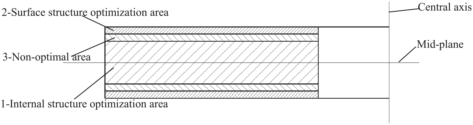
Diagram of optimization area division.
Figure 6 shows the three areas. The first area is the internal structure optimization area. The thickness of the internal structure is 60% of the total thickness of the brake disc. The main function of this area is to provide enough rigidity and strength to prevent the high-speed and heavy-duty brake disc from being crushed by retardation pressure during the braking process. The second area is the surface structure optimization area, which is on the two sides of the brake disc. Its thickness is 20% of the brake disc, and 10% on each side. This area provides a contact area between the brake disc and the brake pad, which is the initial position of heat generation and directly participates in the high-speed and heavy-duty braking process. The last area is the non-optimal area. This area connects the optimized internal and surface structures. Because the brake disc is symmetrical along the mid-plane, the following optimization will be carried out with the simplified model. Only half of the brake disc will be optimized to speed up the calculation.
Equivalent moving load method
Physical model
During the braking process, friction is produced on the contact surface of the brake disc and the brake pad. The friction and retardation pressure are moving loads, and their action positions change with the rotation of the brake disc. This makes it difficult to optimize the internal structure of the brake disc by using ordinary topology optimization methods. The continuous dynamic braking process can be transformed into some equivalent working conditions by using the equivalent moving load (EML) method proposed in this paper. 33 The physical model of the EML method is shown in Figure 7.

Physical model of the EML method: (a) before equivalent and (b) after equivalent.
The actual braking process is shown in Figure 7(a). The brake pad remains stationary and is considered as the reference system. The brake disc rotates around the center axis, and the movement track of the center position on the brake pad is a circle with a radius of r. In Figure 7(b), the brake disc is regarded as the reference system and remains stationary. Over time, brake pads appear in different positions on the brake disc. The figure formed by sequentially connecting the center positions is the inscribed regular polygon of the inscribed circle in Figure 7(b). By using the inward circular polygon approximation algorithm, the following similar mathematical descriptions can be made to the EML method.
Mathematical model
Because the brake pressure changes dynamically during the braking process, it is difficult to determine where the maximum brake pressure appears. Therefore, the load in each equivalent moving load condition is set to the maximum brake pressure, which makes the effect of the load the same as the effect of the maximum brake pressure during braking. This article also optimizes the stiffness and natural frequency of the brake disc, so its comprehensive objective function G(x) can be expressed as:

where, x is the design variable, that is, the relative density of each element. To avoid singularity, xmin = 0.001. i is the total number of elements. The serial number of the equivalent working condition is j, and the total number of EML working conditions is N. Cj(x) is the flexibility of the structure under the jth working condition. Cmax and Cmin are the maximum and minimum values of Cj(x), respectively. They can be calculated by setting the objective function to maximize or minimize Cj(x). Λ(x) is the frequency of the structure. Λmax and Λminmin are the maximum and minimum values of Λ(x), respectively. They can be calculated by setting the objective function to maximize or minimize Λ(x). ω1 is the weight coefficient of compliance with the target. V is the volume of the optimized structure, and V0 is the initial volume of the structure. f is the volume percentage.
Finite element model
Through the HyperWorks software, the internal structure optimization of the high-speed and heavy-duty brake disc with the EML method is completed. The finite element model is shown in Figure 8. The dynamic braking process is equivalent to 60 EML working conditions. The temperature load of the brake disc is received from the result of the thermal-structural coupling analysis in Section 2.1.4 The other constraints are the same as the model of thermal-structural coupling analysis in Section 2.1.3.

Finite element model of internal structure optimization by using the EML method.
The relevant parameters in equation (16) are set as shown in Table 3. Λ, Λ, C, and Cmaxminmax,min are all calculated by using the HyperWorks software. 1 ω1 and f are set artificially according to the requirement of the design.
Internal structure optimization parameters of the high-speed and heavy-duty brake disc.

Result of internal structure optimization
After 48 iterations in the HyperWorks software, the internal structure optimization of the high-speed and heavy-duty brake disc is finished. Figure 9 shows the internal structure optimization result with the density of the element ranging from 0.45 to 1.

Density result of the internal structure optimization.
The topology result is central symmetry around the central axis of the brake disc. The direction of the friction goes clockwise, which is in the positive direction of the z-axis. Since the brake disc is subjected to the brake torque during the braking process, a large stress concentration is generated at the inner hole of the brake disc. This is similar to the stress concentration of the cantilever beam at the distal end. Therefore, in the topology optimization result, the element density at the inner hole is close to 1, and at the same time, the hole size around the inner hole is also very small. To avoid excessive stress concentration, the topology result uses the path shown in Figure 8 to transfer the brake torque to the entire brake disc. The direction of the transmission path is the same as that of the brake torque. Such a structure is conducive to the transmission of the brake torque, which relieves the brake deformation and stress concentration of the brake disc itself. Moreover, Hammerström and Jacobson 34 had proved that this kind of helix structure can reduce the squeal problems of the brake disc.
The result shows that the internal structure of the brake disc is divided into 10 parts. Take one of the 10 parts as an example, the holes on each part show long strips. The distance between adjacent holes is roughly equal. The holes on the same part are parallel and perpendicular to the left edge. This kind of internal structure improves the natural frequency, meanwhile speeds up the heat conduction between the brake disc and the air by increasing the surface area.
Surface structure optimization
Topography optimization method
Design variation in topography optimization
The topography optimization method is a shape optimization method that satisfies the design requirements by machining surface structure changing within the range of specified depth in the normal direction of the optimized surface. Combined with the finite element method, the range of specified depth is transformed into the displacement of nodes in the normal direction of the finite element model, which makes the finite element model meet the optimization requirements. The topography optimization method can improve surface performance, such as reducing deformation, increasing modal frequency, reducing vibration amplitude, etc. The design variable and related parameters of the topography optimization method are shown in Figure 10.

Schematic diagram of topography optimization.
In Figure 10, the design variable is h, the depth of the surface structure. α is the buffer angle set to avoid stress concentration, and wmin is the minimum width of the optimized surface structure. The shaded part is the surface structure to be machined.
Displacement control method
Satisfying the strength requirement is an important target to maintain the safety of the structure. The displacement of some key nodes of the structure is limited to a certain range. It ensures that the displacement and deformation of the structure do not exceed the specified value. Therefore, the displacement control is expressed as

where uir is the r-th displacement of the i-th element and

where

The two-norm form of
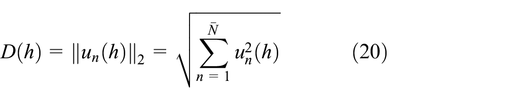
where
Stress control method
In a 2D plane problem, the stress vector of the element
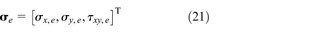
Mohr’s theorems are used as the failure criterion of materials, so the von Mises equivalent stress

The von Mises equivalent stress

where
Mathematical model
The machining depth h (h < 0) of the surface structure is the design variable of the topography multiobjective optimization in this article. In the process of multiobjective optimization, the minimization of maximum displacement and the maximization of the natural frequency of the surface of the high-speed and heavy-duty brake disc are considered simultaneously. The optimization directions of the two optimization objectives are different. Therefore, the multiobjective function is established by using the compromise programing theory, 35 and the weight value of the maximum displacement minimization problem is set to be ω2, then the weight value of the natural frequency maximization problem is set to be (1-ω2). Combined with equations (16) and (22) deduced before in this article, the objective function f(h) of the multiobjective optimization can be expressed as follows

where umaxj(h) is the maximum displacement of the j-th optimization area. F(h) is the first-order natural frequency of the optimized surface structure under the constraint state, and Fmax and Fmin are the results obtained by maximizing and minimizing the first-order natural frequencies of the optimized surface microstructures under the constraint state, respectively. ω2 is the weight coefficient of the displacement objective.
Finite element model
The internal and external radii of the fan surface on the brake pad are r1 = 380 mm, r2 = 360 mm. The effective braking radius re and the maximum brake torque MF can be calculated by the following equations. 36


Finally, the effective braking radius re is 370.09 mm, and the brake torque MF is 3774 N m. To restrain the size of the surface structure of the high-speed and heavy-duty brake disc after optimization, the surface model of the brake disc is divided into 40 equal areas along the circumference direction, as seen in Figure 11. Areas are distinguished by red and blue and meshed by a quadrilateral mesh of 2 mm × 2 mm. The inner hole of the high-speed and heavy-duty brake disc fits with the interference of the spindle, so all points on the inner hole are restricted to the degrees of freedom in x, y, and z directions. The RBE2 connection relationship between the central point of the high-speed and heavy-duty brake disc and the nodes on the effective braking radius is established. The braking torque MF acts on the central point in the plane xOy. The temperature load of the brake disc is received from the result of the thermal-structural coupling analysis in section 2.1.3. Finally, the finite element model of the high-speed and heavy-duty brake disc is obtained as shown in Figure 11.
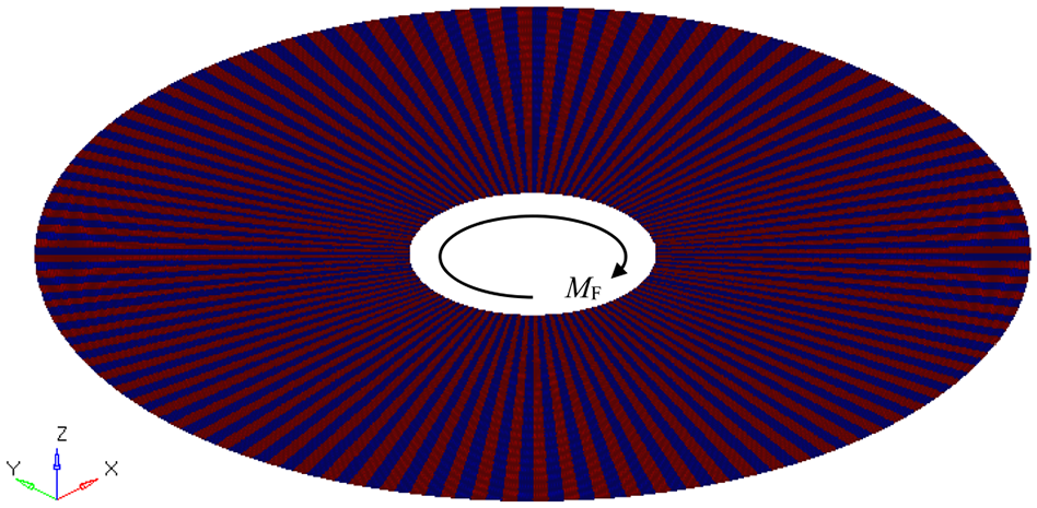
Surface structure optimization model of the high-speed and heavy-duty brake disc.
By choosing one of the 40 areas as the master area and the other 39 areas as the slave areas, the optimization area has a repetitive mode, which simplifies the surface structure optimization model of the high-speed and heavy-duty brake disc.
As shown in Figure 12, the spatial coordinate system (right-handed Cartesian coordinate system) is established. Point A is the origin of the coordinate system, point B is the point on the x-axis positive direction, point C is the point in the xOy plane, and point D is the point on the z-axis positive direction. Every master/slave area has its spatial coordinate system. The definition of the spatial coordinate system of the master area is completed by defining the above 4 points, and the same method is used in the slave areas. This ensures that the optimization results of all the master/slave areas are consistent and repeatable, to facilitate the subsequent reconstruction and the machining of the optimized surface structure.

Space coordinate system setting of the master/slave area.
The relevant parameters in equation (24) are set as shown in Table 4. Fmax and Fmin are all calculated by using the HyperWorks software.
1
Surface structure optimization parameters of the high-speed and heavy-duty brake disc.

Optimization results
Based on the finite element model and optimization constraints described above, the surface structure of the high-speed and heavy-duty brake disc is optimized. The optimization result is shown in Figure 13.

Result of the surface structure optimization.
The shape change of the brake disc is shown in Figure 13. Because the optimization parameter hmin is set to be −4, the maximum and minimum values are 0 and −4, respectively. The smaller the value is, the greater the depth of processing required. The optimized surface structure of the brake disc can be divided into two parts (divided by white dotted line), the outer area of the brake disc (friction contact area) and the inner area of the brake disc (rigidity strengthening area).
In the friction contact area, the area of the surface structure to be machined and the area of the non-machined surface each account for 50%. The surface structure is evenly distributed within the frictional contact area. The symmetry of the brake disc is ensured so that its center of mass remains at the center of the brake disc. During the braking process, the contact between the brake disc and the brake pad in the friction contact area is the main area of heat generation, and the shape of the surface structure in the friction contact area is thick and long, and its distribution is relatively scattered. The surface of the brake disc is divided into 40 master/slave areas before optimization, and each area has the same structure. The connecting lines between the master/slave areas are straight, but in a single master/slave area, the connecting lines between the surface structures to be machined and the non-machined surface have obvious features. Now describe one of the areas, as seen in Figure 13. In this selected master/slave area, the shape of the connecting line is a trapezoidal sawtooth. It is discontinuous in the radial direction. Such a connection line can alleviate the high temperature and stress concentration on the surface of the brake disc.
In the rigidity strengthening area, the shape of the machined surface structure is short and small. The structure presents radial distribution along with the brake disc. and its distribution is relatively denser than the surface structures in the friction contact area. The primary function of these structures is to create a sufficient pleat shape to increase the stiffness of the brake disc surface, the principle of which is similar to the corrugated structure for packaging.
Reconstruction and mechanic performance verification
Reconstruction
The outline of the reconstructed high-speed and heavy-duty brake disc comes from the result of the surface and internal structure multiobjective optimization. By using the data tracing technology and considering the manufacturing process, the outline can be obtained directly. The results shown in Figures 9 and 13 are in irregular shapes. To manufacture the new brake disc easily, the structure of the brake disc needs to be reconstructed, and only the main features in the results are retained.
The 3D printed model of the brake disc shrunk 50 times is shown in Figure 14. Figure 14(a) shows the reconstructed internal structure of the brake disc according to the result in Figure 9. The reconstructed internal structure of the brake disc can still be divided into 10 identical areas like the optimization result shown in Figure 9. However, in each area, the grooves are reconstructed from a wave shape into a smooth strip shape, and the groove width in each area is the same, which facilitates the internal structure of the brake disc to be milled without changing cutting tools in other sizes. Figure 14(b) shows the reconstructed surface structure of the brake disc according to the result in Figure 13. After reconstruction, the surface of the brake disc can still be divided into two areas as in Figure 13, namely the rigidity strengthening area and the friction contact area. The rigidity strengthening area simplifies the optimization results in Figure 14, reducing the processing difficulty of the structure in the region. In Figure 13, the optimization result of the friction contact area is relatively regular and clear, and the trapezoidal sawtooth structure is retained during the reconstruction process. However, the trapezoidal sawtooth structure of the brake disc surface could increase the wear of the friction material. In addition, the volume of the brake disc after reconstruction is significantly reduced. That is, the quality of the disc body is reduced.

Reconstruction model of brake disc with internal and surface structures by 3D printing: (a) optimized internal structure and (b) optimized surface structure.
After reconstruction, there is a slight difference between the reconstructed structure and the optimization results. Moreover, it is not clear whether the performance of the high-speed and heavy-duty brake disc can meet the requirements analyzed in Section 2. Therefore, it is necessary to verify the performance of high-speed and heavy-duty brake disc with internal and surface structures.
Thermal-structural coupling analysis verification and results
The working conditions and boundaries are the same as the high-speed and heavy-duty brake disc without surface and internal structures in Section 2.1. The thermal-structural coupling analysis finite element model of the high-speed and heavy-duty brake disc with surface and internal structures is shown in Figure 15.

Thermal-structural coupling analysis finite element model of reconstructed brake disc and brake pad.
With the Abaqus software, the thermal-structural coupling analysis of the high-speed and heavy-duty brake disc with internal and surface structures is finished. The total braking time is 18.03 s. Contours of displacement, surface temperature, and equivalent stress after thermal-structural coupling analysis of the high-speed and heavy-duty brake disc with internal and surface structures are shown in Figure 16.
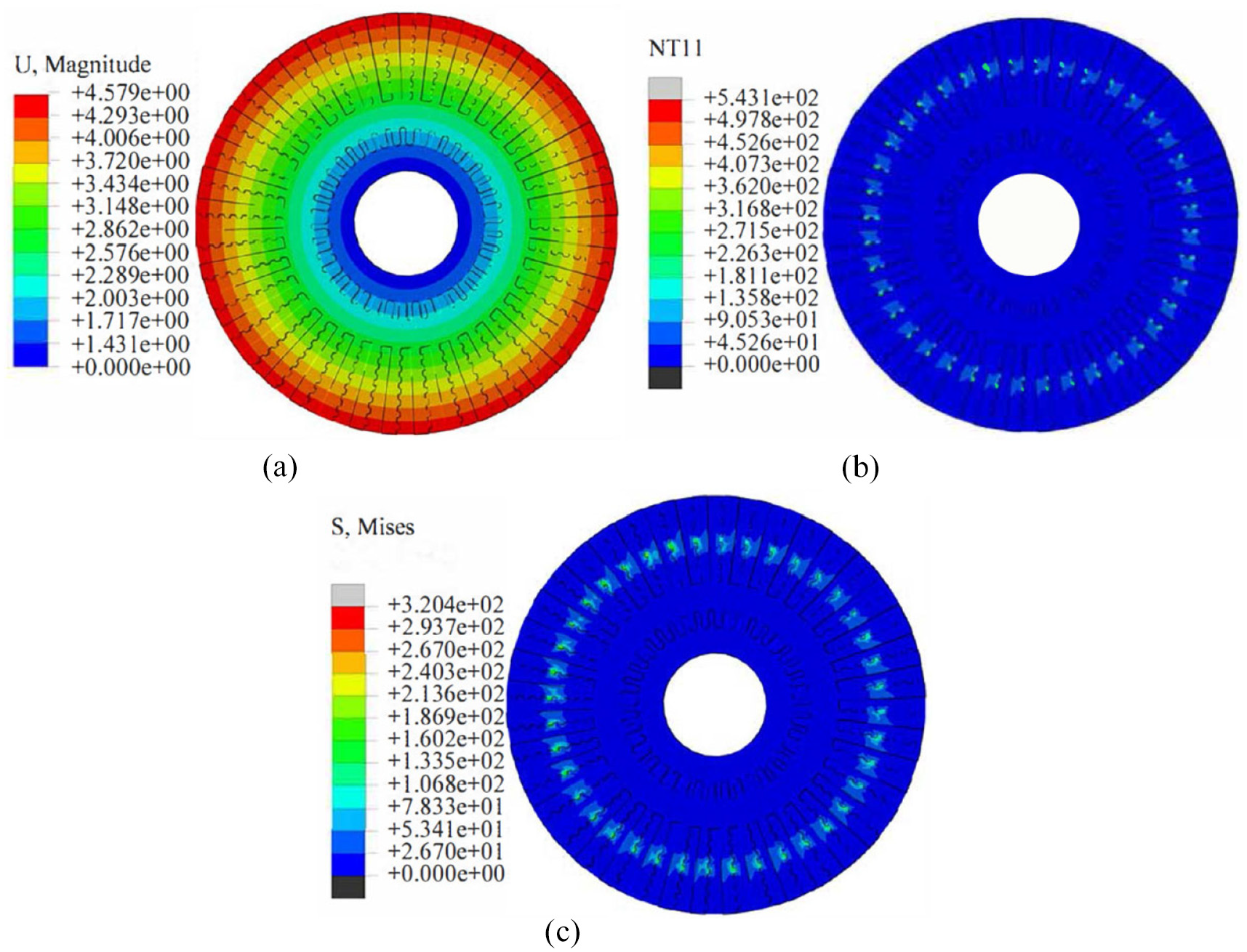
Thermal-structural coupling analysis result contours of the reconstructed brake disc: (a) brake displacement, (b) surface temperature, and (c) equivalent stress.
Figure 16(a) is the displacement contour of the brake disc surface. The displacement value increases from the inner side to the outer side of the brake disc, which is the same as the result of the brake disc without surface and internal structures. The maximum displacement of the brake disc with surface and internal structures is 0.4579 mm. Figure 16(b) and (c) show the surface temperature and equivalent stress, respectively. Because of the existence of the surface structure on the brake disc, the surface temperature and the equivalent stress are not continuous. The maximum temperature is 543.1°C, and the maximum equivalent stress is 320.4 MPa. The maximum value appears at 12.17 s. The surface temperature and equivalent stress contours prove the previous analysis of the optimization results. The high temperature and stress concentration areas are not continuous.
Modal analysis verification and results
The modal analysis verification is conducted by using the HyperWorks software, which provides the former four modes shown in Figure 17. The frequencies of the former four modes are 346.93, 347.27, 366.66, 435.57 Hz, respectively. The vibration modes of the former four modes are stretching along the line y = x in the plane xOy, stretching along the line y = −x in the plane xOy, radial stretching along the circumference of the brake disc, and stretching along y = x and y = −x, respectively.
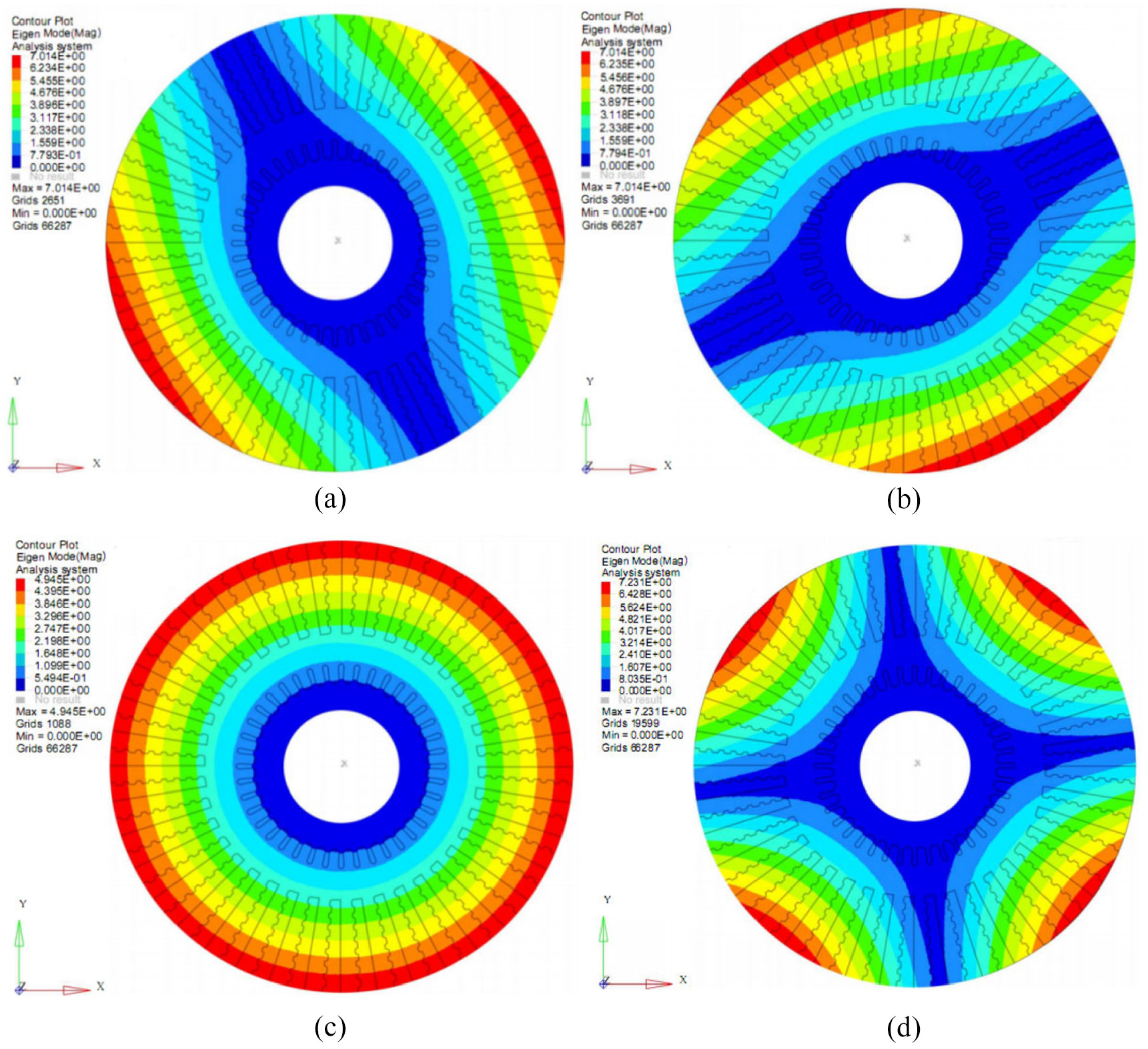
Modal analysis results of the reconstructed brake disc: (a) first mode, (b) second mode, (c) third mode, and (d) fourth mode.
Performance comparison
Performance comparison of the high-speed and heavy-duty brake disc before/after the internal and surface structures multiobjective optimization is shown in Table 5.
Performance comparison of high-speed and heavy-duty brake disc before/after optimization.

Conclusions
In this paper, aiming at the brake performance requirements of disc brake discs under high-speed and heavy-duty conditions, the optimization technology of brake disc structure under multi-physical coupling is carried out, and a multi-physical coupling model of high-speed and heavy-duty disc brake is established. The mechanism of high-speed heavy-duty braking under the multi-physical coupling is revealed. The structural topology optimization method based on EML and topography optimization method for displacement and stress control are proposed. The internal and surface structures of high-speed and heavy-duty brake disc are optimized, and the performance of the optimized brake discs is verified. Based on the above research, this paper draws the following conclusions:
Aiming at the multi-physical coupling behavior formed during the vibration process of loads such as brake pressure, friction resistance, and temperature loads under high-speed and heavy-duty braking conditions, a multi-physical coupling analysis method is proposed. A multi-physical coupling model for high-speed and heavy-duty disc brakes is established. The multi-physical coupling analysis of the brake disc is carried out to simulate actual high-speed and heavy-duty conditions, and the mechanism of high-speed and heavy-duty braking is revealed, and the performance of the brake disc under high-speed and heavy-duty braking conditions is obtained. The maximum surface deformation of the studied high-speed and heavy-duty brake disc during the braking process is 0.8 mm. Both the surface temperature and equivalent stress of the brake disc present a circular distribution, the frequencies of the former four modes are 288.56, 288.58, 310.14, and 382.33 Hz.
Aiming at the characteristics that the magnitude, direction of action, and location of the moving load change over time, this is equivalent to multiple equivalent moving load conditions, and a structural topology optimization method based on equivalent moving loads is proposed. The moving load composed of brake pressure and friction resistance in high-speed and heavy-duty braking conditions is converted into multiple equivalent moving load conditions distributed on the brake disc. The optimization goal is to minimize the static flexibility and maximize the dynamic frequency under the coupling effect, and the multiobjective topology optimization of the internal structure of the brake disc is carried out, and the internal structure of the brake disc is obtained. The proposed structural topology optimization method based on equivalent moving loads can obtain the optimal structure under sufficient equivalent moving load conditions. The optimized internal structure of the brake disc can transmit the load to the outer edge of the brake disc, which has the characteristics of fast heat dissipation under the effect of temperature load and vibration coupling and can increase the modal frequency.
In response to the requirements of high-speed and heavy-duty braking conditions for the surface performance of brake disc, the research of a multiobjective surface topography optimization method that can control global displacement and stress is proposed. Furthermore, taking the interface stiffness and frequency improvement under the coupling action as the optimization objective, the multiobjective optimization of the brake disc interface is carried out, and the surface structure of the brake disc is obtained. The surface topography optimization method oriented to displacement and stress control can be set in the surface to meet the surface displacement and stress constraints, and the braking interface with improved surface stiffness and modal frequency can be optimized. The optimized surface structure of the brake disc is divided into friction contact area and rigidity strengthening the area. Under the action of temperature load, the braking interface has the function of providing sufficient heat dissipation and holding wear debris. Under the restraint of braking torque and vibration frequency, the braking interface of the brake disc has the characteristics of improving the stress distribution and reducing the stress concentration.
Based on the optimization results of the internal and surface structure of the brake disc, combined with the manufacturability of the brake disc, the internal and surface structure of the brake disc is reconstructed, and the performance of vibration characteristics and multi-physical coupling characteristics are verified. The maximum deformation of the brake disc surface after optimization is 0.46 mm, which is 42.78% lower than before optimization. The former four modal frequencies are 346.93, 347.27, 366.66, and 435.57 Hz, respectively, which are increased by 20.23%, 20.34%, 18.22%, and 13.93% respectively compared to before optimization. The surface temperature and stress distribution of the brake disc is affected by the braking interface of the high-speed and heavy-duty brake disc in a discontinuous circular ring distribution, and the stress concentration at the contact position with the high-speed rotating main shaft is relieved.
This paper considers the influence of friction heat between the brake disc and the brake pads, the thermal-mechanical coupling mechanism of the brake interface during the braking process is analyzed, and then the structure of the brake disc is optimized. However, in long-term braking conditions, wear and fatigue of the brake disc would occur, especially under high-speed and heavy-duty braking conditions. Therefore, to obtain a wear-resistant and anti-fatigue brake disc, further research of an optimized method is needed.
Footnotes
Appendix
Handling Editor: Chenhui Liang
Declaration of conflicting interests
The author(s) declared no potential conflicts of interest with respect to the research, authorship, and/or publication of this article.
Funding
The author(s) disclosed receipt of the following financial support for the research, authorship, and/or publication of this article: The authors gratefully acknowledge the financial support of the National Natural Science Foundation of China (No. 51675075), the Scientific Research Project of the Education Department of Liaoning Province (No. LJKZ0479), and the Transportation Science and Technology Project in Liaoning Province (No. 2021048).
Data availability
The data used to support the findings of this study are available from the corresponding author upon request.