
Abstract
Sub-surface damage during machining of aluminum-based metal matrix composites (MMCs) has been modeled using finite element models. These models are based on reinforcement particles size and volume fractions and particles are distributed uniformly in the metal matrix. In order to simulate particle debonding cohesive zone elements (CZE) have been incorporated along the parting line. In addition, failure criteria based on brittle fracture have been added for ceramic particles to simulate particle fracture. To reduce computational time and simplify the model both CZE and particle fracture is limited to the reinforced particles along the parting lines facing the tip of the cutting tool. The damage depth beneath the machined surface is measured by using the non-zero plastic strain values in the equivalent plastic strain contours obtained from the FE models. The results were compared against published experimental data and found to be in good agreement.
Introduction
Metal matrix composites (MMCs), due to their remarkable physical and mechanical properties, have attracted considerable interest from industries, particularly the automotive and aerospace sectors. They have superior combinations of high-temperature performance, elevated thermal conductivity, greater strength and rigidity, higher strength-to-weight ratio, as well as lower thermal expansion coefficient in comparison to polymer matrix composites (PMCs). 1 MMC, like many other composites, is a mixture of two or more materials with a matrix (metal) composition and a reinforcement structure (in the form of particles, whiskers, or fibers). 2 They present exciting possibilities to customize materials to particular design requirements and provide more alternatives for broader applications in various conditions to fit the user needs. 3
On the one hand, MMCs are useful in demanding applications, but they are difficult to process using traditional machining procedures (like milling, turning, and drilling). 4 The key problem is its heterogeneous composition that contributes to anisotropic thermal and mechanical properties hence the varying thermal and mechanical forces on cutting tools.5,6 Moreover, the abrasive properties of the reinforced particles substantially impact the life of the tool. The machining of MMCs is indeed difficult due to the extreme tool wear rate and the presence of strong unstable cutting forces. 7 Certainly, the performance of these materials relies heavily on the reinforcement, the matrix, and the interface between the matrix and reinforcement particles. The hard and rigid reinforced particles interact with the cutting tool throughout machining and operate like sharp edges, contributing to an increase in the tool wear, higher surface roughness, and greater cutting forces. 8 Machining factors such as tool geometry, feed rate, speed, and cutting depth also influence machining forces and surface integrity. 9 In particular, the rise in cutting speed increases the quality of the surface and feed worsens it, while the cutting depth exhibits a less significant impact on the properties of the machined surface. 10 The feed has a significant impact on surface roughness, while the cutting speed has an impact on tool wear, cutting power, and forces. 11
It is imperative to have a comprehensive and profound perspective into the MMC behavior under different cutting situations to facilitate its optimum machining. 12 The unique machining mechanics of MMC, therefore, demand greater attention from both industry and academia. In the last two decades, researchers have done a large number of experimental studies, but finite element (FE) has attracted greater consideration for its advantages, particularly cost-effectiveness, lesser resource needs, and its ability to holistically examine machining processes such as the impact of machining variables on the machined surface, interaction between tools and particles, chip removal mechanisms, etc. FE simulation has become the most practicable way to evaluate and comprehend the machining process and to assess the effect of various machining variables. Lately, there have been a variety of attempts to model the machining of MMCs. 13 This could be because innovations in computing power have allowed complex numerical simulations to be effectively performed. FE methods are also among the most commonly known analytical techniques in the field of machining simulation.14,15 One of the first researches on the machining of MMCs utilizing the FE model was done by Monaghan and Brazil.16,17 During the machining operation, a multi-phase two-dimensional (2D) model for aluminum/silicon carbide (Al/SiC) based MMC was created to analyze the flow stress, failure process, residual stresses, damage conditions, etc. Similarly, the thermal and mechanical interplays of the tool-chip, as well as tool-workpiece nodes, were considered in a robust three-dimensional (3D) FE model of the cutting tool explored by El-Gallab and Sklad 18 through the turning of Al/SiCp composite. They inferred that the machining of Al/SiCp culminated in three heat origins released at the tool-chip interface, tool-workpiece juncture, and the shear plane. Furthermore, spiky (or rough) SiC particles incorporated in the Al matrix led to excessive tool wear and unacceptable surface quality in Al/SiCp composite machining, making composites challenging to machine using traditional production methods.
It is important to investigate the basics of the MMC machining by analyzing the impact of reinforcement particles, the significance of the volume (size and distribution) of reinforcement particles, damage mechanism, tool-particle interaction, the impact of machining variables (feed, cutting depth, speed, etc.) on surface quality, tool wear, etc. A plethora of studies have been carried out in the literature to comprehend the mechanics of machining MMCs. For example, the orthogonal machining of the alumina (Al2O3)/Al 6061 MMC composite and a tungsten carbide tool was studied by Zhu and Kishawy. 19 By using temperature-dependent material physical characteristics, a plane-strain thermo elasto-plastic FE model was established. In this model, the interface failure mode was integrated amidst the Al matrix and Al2O3 particles. It was observed that the estimated components of cutting force improved with feed and the von mises equivalent stress distributions showed an increasing trend for particle stress in the undeformed chip and attained a maximum level for the reinforcements in the primary shear zone. Owing to the breakdown of the Al2O3 particle’s interface, the hard particles were debonded or partially debonded and scratched the face of the tool rake, producing greater wear on the tool. The FE cutting simulation model formulated by Pramanik et al. 20 was based on the three-particle distribution scenarios. The three scenarios were particles scattered over the cutting path, particles on the cutting path, and particles beneath the cutting path. During orthogonal cutting of composite SiCp/Al6061 materials with 20% SiC flecks, the interaction between the cutting tool and SiC particles was investigated. The data revealed that the principal source of tool wear was particle sliding on the tool’s contact surface. Dandekar and Shin 21 performed multi-step 3D machining simulations for an A359 Al matrix composite reinforced with 20% SiC component. To anticipate damage during machining, the thermo-elastic–plastic failure model and the cohesive zone model were used together. Upon an increment in the cutting force, the damage depth increased, confirming that the damage depth was dependent on the cutting force. The model reported in this research was adept to figure out all the failure occurrences, including particle fracture, debonding at the particulate–matrix junction, and matrix void generation. A thermal-displacement coupled FE model was implemented by Zhou et al. 22 to study the impact of higher volume fractions and large-sized SiC particles. The cutting force and the von mises equivalent stress were analyzed in-depth under various cutting settings. The findings demonstrated that the cutting speed and depth had a substantial influence on the cutting force, while the expulsion of the SiC particle depended on the position of the cutting tool relative to the particle. With an increment in the cutting speed, the cutting force dropped, whereas, with a rise in cutting depth, it increased almost linearly.
To simulate the behavior of all critical elements, such as the matrix, particles, and particle-matrix interface, throughout MMC machining, a micro-mechanical FE study can also be undertaken. Different components of the mechanism, such as particle debonding and fracture, as well as various tool-particle interaction scenarios, were explored by Ghandehariun et al. 23 To create a 2D microscopic model of SiCp/Al composite materials, Fathipour et al. 24 employed ABAQUS/Explicit software. The SiC particles with 20% volume fractions, assumed as an elastic material, were considered in this model. After the particle-matrix interface was linked together, binding constraints were applied. The Johnson-Cook constitutive model was used in this study. The variations in cutting force and morphology of chip formation were examined. Williams et al. 25 used a 3D FE modeling technique to investigate the effect of particle/matrix interface debonding in Al alloy matrix composites reinforced by SiC particles. The impact of particle volume fractions and volume size on elastic and plastic characteristics was investigated. They also used user-defined cohesive zone elements to mimic interfacial debonding. The angular particles were more susceptible to interfacial debonding and displayed a greater degree of load transfer. In the angular particles, a greater decrease in stress was recorded due to the flat surfaces, normal to the loading axis, that bear load. 2D FE modeling employed by Wang et al. 26 explained the forming process of the chip and machined surface in the cutting of SiCp/Al composites. Multi-phase modeling including a spherical SiC reinforcement phase haphazardly dispersed in a 6061 Al alloy matrix was applied. Simulation of the orthogonal cutting procedure with an augmenting volume fraction of SiC reinforcement particles was employed to study the consequences of different percentages of reinforcement particles. Due to the existence of randomly scattered SiC particles, the cutting force pattern derived from machining SiCp/Al composites was dominated by considerable high fluctuations. 20 Particle debonding, small holes, elevated and impacted particles were present in the simulated surface morphology. By combining the three-phase friction model, Duan et al. 27 created a FE model of inconstantly allotted round particles. This three-phase friction model assumed the impact of matrix adhesion, two-body abrasion, and three-body rolling on friction at the tool-chip interface in the machining of Al/SiCp composites. The cutting simulation’s chip morphology was well-matched with the experiments and was identified as a saw-toothed chip. According to this analysis, the chip formation simulation showed that the shear zone deformation process in Al/SiCp composite machining could be categorized into four phases: shear localization manifestation, shear localization formation, initiation, and propagation of the crack. Researchers carried out a FE based analysis of a gas turbine’s rotor blade made up of MMC. The results of MMC material blade were compared with Ti6Al4V blades. MMC-based blades had less mass, less tip displacement, and lower maximum stress values, according to the findings. 28 Particle based and fiber based MMCs were studied for ductile damage by Drabek and Böhm. 29 In an another study, FE modeling has been utilized for Al/SiCp composites’ solidification process. 30 A three phase MMC was developed and analyzed using FE modeling by Saxena et al. 31 The results demonstrated a good agreement between the experimental data and the micro-mechanical and macro-mechanical FE analysis models. The findings of the FE analysis showed that the waste steel chip powder particles exhibited more stressed than the TiB2 powder particles.
The residual stress implications on the tensile characteristics of particle reinforced MMCs were documented by Zhang et al. 32 They assessed the damage mechanism by devising a representative volume element (RVE) based FE model. In this investigation, damage to SiCp/Al composites involved damage to various components, matrix, SiC particles, and interface. The tensile loading behavior of 15 vol.% SiCp/2009Al was modeled with different particle sizes (5 and 13 µm). The consequences of load transfer, plastic strain gradient, reduction of grain size, thermal residual stress/strain, and MMC damage were analyzed. According to their findings, load transfer played a crucial role in strengthening MMC, residual stress/strain induced by the MMC cooling process enhanced the yield strength and the size effect of MMC was primarily driven by grain refinement and strengthening of plastic strain gradient. An orthogonal cutting FE model developed by Laghari et al. 33 simulated SiCp/Al composite machining after randomly distributing the particles through the matrix. The constitutive models of the matrix, particles, as well as interface layers, were independently established. In this research, the SiC particles were adapted in the form of an oval shape. This model was employed to research the influence of cutting speed, feed rate, cutting thickness, and various volume fractions of SiC particles on surface formation, chip morphology, stress distribution, and cutting forces. When the particles came into contact with the cutting route, the failure mechanism was largely brittle fracture, according to the results. The particles were predominantly fractured and delaminated from the matrix beneath the cutting path, while the particles and matrix were mostly delaminated over the cutting path. The findings also revealed that the interface layer between matrix and reinforcement had a significant impact on stress and strain transfer in the SiCp/Al MMC during the cutting process. The analysis managed to show that with the rise in cutting thickness, the cutting force had gone up, but the effect of cutting speed was not apparent. On the cutting surface, there were abnormalities such as holes from particle smashing, abrasive grooves and cracks from matrix ripping, and protrusions from particles pushed into the matrix and partially exposed to the outside. Furthermore, as the feed rate increased, the chip design moved from spring-shaped coils to C-type chips, the number of curls gradually decreased, and the radius of the chip curls steadily improved. Umer et al., 34 optimized the tool wear rate from the data obtained through FE modeling of machining of Al-SiC MMCs. Multi objective genetic algorithm (MOGA-II) was utilized for optimization. Results revealed that low cutting speed and moderate feed rate are optimal for less tool wear.
One of the critical factors in evaluating the quality of the machined MMC workpiece is the sub-surface damage either in form of matrix deformation or reinforced particle debonding and particle fracture. Most of the previous works related to sub-surface damage in MMC are limited to experimental studies. Despite applications of FE models in modeling of MMC machining, no work has been reported to date regarding the modeling of sub-surface damages utilizing 2D or 3D FE models. Thus, the focus of this work is to assess the capabilities of the micromechanics-based FE models in predicting the sub-surface damage during MMC machining. The models are validated by published experimental data by Kannan and Kishawy. 35
Materials and methods
Orthogonal cutting simulations utilizing finite element (FE) modeling were performed to examine sub-surface damage while machining aluminum-based MMCs. Table 1 shows the various cutting speeds, feed rates, average particle sizes, and cutting tool geometry employed in the simulation.
Finite element (FE) models’ parameters for cutting conditions and tool geometry.

The MMC workpiece was made from an aluminum alloy called Al-6061 and reinforced with alumina (Al2O3) particles. The average grain size of the polycrystalline diamond (PCD) cutting tool utilized in the analysis is 15 µm. The mechanical and physical attributes of the matrix, reinforcing particles, and tool material are shown in Table 2.
Characteristics of workpiece and cutting tool.

For simultaneous temperature-displacement study with the stationary workpiece and progressive tool, ABAQUS/Explicit was utilized. The circular reinforced particles with a homogeneous dispersion were used to create the MMC workpiece. As a result of a single mesh for the whole workpiece, there were no tie-constraints linking matrix and reinforcement particles. To aid in the smooth chip production requirement, a separation line was developed with an allocated damage. The mesh was improved at the tool tip to account for substantial temperature fluctuations. Four-node continuum planar strain elements with limited integration and temperature degrees of freedom (CPE4RT), were used in the investigation. The total number of nodes vary from model to model, on the average there were around 20,000 nodes in a single FE model.
Until the damage criterion is met, the matrix material is assumed to be a temperature-dependent elasto-plastic material. Using the Johnson-Cook (J-C) strain, strain rate, and temperature dependent plasticity model, the mises flow stress was computed. Because the workpiece material is subjected to high strains, quick strain rates, and high temperatures, this model is ideal. As a result, the mises flow stress can be quantified using equation (1).

where A, B, C, n, and m characterize the material constants, including yield stress constant, strain hardening constant, strain rate hardening constant, strain hardening exponent, and coefficient of temperature dependence, respectively. Torsion, tensile, and dynamic split hopkinson bar tests were conducted to establish these material constants for the J-C equation (equation (1)). Furthermore,
The J-C constants for Al-6061 alloy.

The chip detachment from the workpiece was modeled using a parting line made up of sacrificial elements. The J-C progressive damage criterion, which considers strain, strain rate, temperature, and pressure stress was used to define these elements. The damage factor was calculated for each element using equation (2).

where

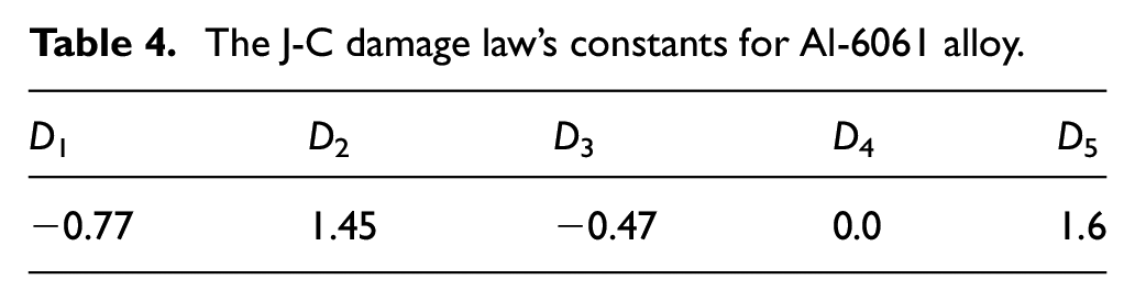
where σ* symbolizes the ratio of pressure stress to von mises stress. Material constants D1 to D5 are established using tensile and torsion testing. Table 4 summarizes the J-C damage parameters for matrix material.
The J-C damage law’s constants for Al-6061 alloy.
The reinforcement particle materials are assumed as perfectly elastic that is no plastic deformation until the commencement of fracture. Brittle cracking model available in ABAQUS is utilized to simulate the failure of the reinforcement particles. Two approaches are commonly used to model matrix-reinforcement debonding. The first is to employ cohesive zone elements that degrade as a result of separation. Some experts believe that the interface bonding strength should be around 50 J/m.2,21,23 Another method is matrix element collapse around the reinforcement particles. In this study cohesive zone elements were utilized to model the debonding between matrix and reinforcement particles. The J–C damage law in equation (3) shows that the debonding energy is proportional to the failure stress–strain values.
To mimic the interaction between the tool and the workpiece, the Coulomb friction law is applied. According to this law, when the shear flow stress of the workpiece material exceeds the critical value of frictional stress, there is no sticking and relative motion or slide occurs. Conversely, sticking happens when the shear flow stress is lower than the critical value of frictional stress. The frictional stress is estimated using the following equation (equation (4)).

where s, ρ, and τ are the frictional, normal, and shear flow stresses, respectively, at the tool rake face. The coefficient of friction is considered to be 0.15, according to Zhu and Kishawy. 19
Due to the fact that the computing effort of an explicit analysis is proportional to the size of the smallest element, excessive matrix material deformation caused by hard reinforcement particles leads to really sluggish computation. Artificially applying mass to the selected elements can assist to alleviate this difficulty and accelerate the processing. In ABAQUS/Explicit, this option is called as mass scaling and is therefore used for MMC cutting simulation. 37
Results and discussions
Micromechanics based FE models, that is models developed considering reinforcement particle size and volume distribution in the matrix can be utilized to simulate tool-particle interaction. By utilizing the cohesive elements between reinforcement particles and matrix de-bonding can be simulated. Similarly using brittle failure criterion for reinforcement particles, fracture can be predicted with the advancement of the tool into the workpiece. Figure 1 shows two instances of tool-particle interaction as tool the advances into the MMC workpiece. Particle fracture can be noticed for the first particle along the cutting line as the cutting progresses in Figure 1 (top). Similarly, high stresses can be seen in the cohesive elements around the second reinforcement particle and de-bonding initiates. Further advancement of the cutting tool is shown in Figure 1 (bottom) and due to high surface traction more cohesive elements deleted and de-bonding continues to progress for the second reinforcement particle. Also, it can be visualized that as the portion of the reinforcement particles start to detach from the metal matrix either by de-bonding or fracture, stress decreases as depicted in Figure 1.

Tool-particle interactions modeling during MMC machining.
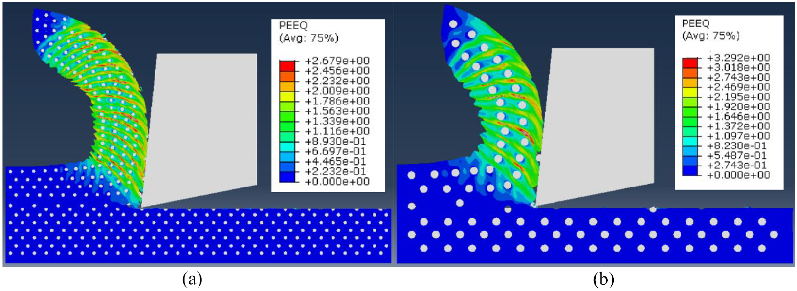
Finite element model results for damage depth comparison for different particle sizes are shown in Figure 2. It is evident from the Figure that damage depth decreases with increase in particle size. The gray area in the figures refers to the plastically deformed workpiece material (non-zero plastic strain) and the damage depth is calculated by measuring the thickness of the plastically deformed area below the machined surface. The damage depth is calculated at six different places on the machined surface and the average value is taken for comparison with the experiments. Figure 3 depicts the comparison for model results with the published experimental data. It is evident from the figure that the model predictions are in good agreement with the experimental findings and the error is around 9%. As the particle size is increased with the same volume fraction, the average distance between the reinforced particles increases. Consequently, large spacing between the reinforcement particles results in less localization of plastic strains in the matrix and this leads to reduced damage depth. This can be well understood by comparing the equivalent plastic strain contours for both particle sizes as shown in Figure 4. Although the magnitude for maximum plastic strain is higher with larger particles, the strain contour is comparatively uniform i.e. less localization of plastic strain as compared to the model with smaller reinforced particles. Similar gradient occurs also across the machined surface as shown in Figure 2 and hence damage depth is reduced with large particle size.

Damage depth comparison for different particle sizes (a) 9.5 µm, (b) 20 µm, V = 60 m/min, f = 0.1 mm/rev, volume fraction = 10%.

Damage depth results for models and experiments with different particle sizes, V = 60 m/min, f = 0.1 mm/rev, volume fraction = 10%.
Equivalent plastic strain for different particle sizes (a) 9.5 µm, (b) 20 µm, V = 60 m/min, f = 0.1 mm/rev, volume fraction = 10%.
Mises stress contours along the workpiece matrix for different particle sizes are shown in Figure 5. As shown high stressed regions are more frequent along the chip with workpieces having smaller reinforcement particles. On the other hand, workpieces with large reinforcement particles have comparatively low high stressed bands. Similar pattern can also be examined on the machined workpiece surfaces for the two models and high stressed regions are more consistent with smaller particle size. This is due to high frequency interactions between the tool and the reinforcement particles which leads to large plastic deformation along and beneath the machined surface for smaller size particles.

Mises stress contours for different particle sizes (a) 9.5 µm, (b) 20 µm, V = 60 m/min, f = 0.1 mm/rev, volume fraction = 10%.
Figure 6 shows the damage depth obtained from FE models at different feed rates. It can be visualized from the Figures that damage depth increases with rise in feed rates. Figure 7 depicts a comparison between the model and experimental data. As depicted from the figure the models show similar trend, however they underestimate the damage depth by around 11%. This is due to the simplified FE models in which particle fracture and debonding is considered only along the cutting line. The increase in damage depth with increase in feed rate is also observed by other researchers.34,38 Higher feed rate results in higher cutting and thrust forces that leads to higher stresses along the machined surface. The high stresses along the machined surface induces more plastic strain and consequently damage depth increases. These observations can also be verified by examining contours of equivalent plastic strain and mises stress in Figures 8 and 9 respectively. It can be noticed that the magnitude of equivalent plastic strain increases with feed rate as shown in Figure 8. Also, with higher feed rates, highly localized plastic strain regions can be seen clearly near the tool-chip contact area. Similarly, differences can be marked in stress contours for the two feed rates as shown in Figure 9. High stressed regions are more frequent with large feed rates particularly near the tool-chip contact areas. This is due to high sticking friction with thicker chips resulting in increased tool-chip contact area.

Damage depth for different feed rates (a) f = 0.1 mm/rev, (b) f = 0.3 mm/rev, V = 60 m/min, particle size = 17 µm, volume fraction = 10%.

Damage depth results for models and experiments with different feed rates, V = 60 m/min, particle size = 17 µm, volume fraction = 10%.

Equivalent plastic strain for different feed rates (a) f = 0.1 mm/rev, (b) f = 0.3 mm/rev, V = 60 m/min, particle size = 17 µm, volume fraction = 10%.

Mises stress contours for different feed rates (a) f = 0.1 mm/rev, (b) f = 0.3 mm/rev, V = 60 m/min, particle size = 17 µm, volume fraction = 10%.
Damage depth results obtained from FE models at different cutting speeds are shown in Figure 10. It is obvious that the damage depth does not change much with the cutting speed, however a slight reduction can be noticed. Figure 11 compares the simulation results with the experiments and the average error is around 13%. At lower cutting speed the effect of thermal softening is low and strain hardening predominates resulting in higher stresses on the machined surface. With higher cutting speed mechanical loads reduce and thermal softening predominates. This leads to decrease in damage depth with the rise in cutting speed. Equivalent plastic strain contours at different cutting speeds are shown in Figure 12. The strain contours are found to be similar except that the magnitude escalates with the increase in cutting speed. This is due to higher temperatures and more thermal softening with the rise in cutting speed. Figure 13 shows the mises stress contours in the MMC matrix at different cutting speeds. It is clear from the contours that high stressed regions are more pronounced at low cutting speed. As stated above at lower cutting speeds the matrix is harder and thermal softening effects are low resulting in higher stresses as shown by the maximum mises stress values at different cutting speeds.

Damage depths at different cutting speeds (a) V = 24 m/min, (b) V = 60 m/min, (c) V = 100 m/min, f = 0.1 mm/rev, particle size = 23 µm, volume fraction = 20%.

Damage depth results for models and experiments with different cutting speeds, f = 0.1 mm/rev, particle size =23 µm, volume fraction = 20%.

Equivalent plastic strain at different cutting speeds (a) V = 24 m/min, (b) V = 60 m/min, (c) V = 100 m/min, f = 0.1 mm/rev, particle size = 23 µm, volume fraction = 20%.
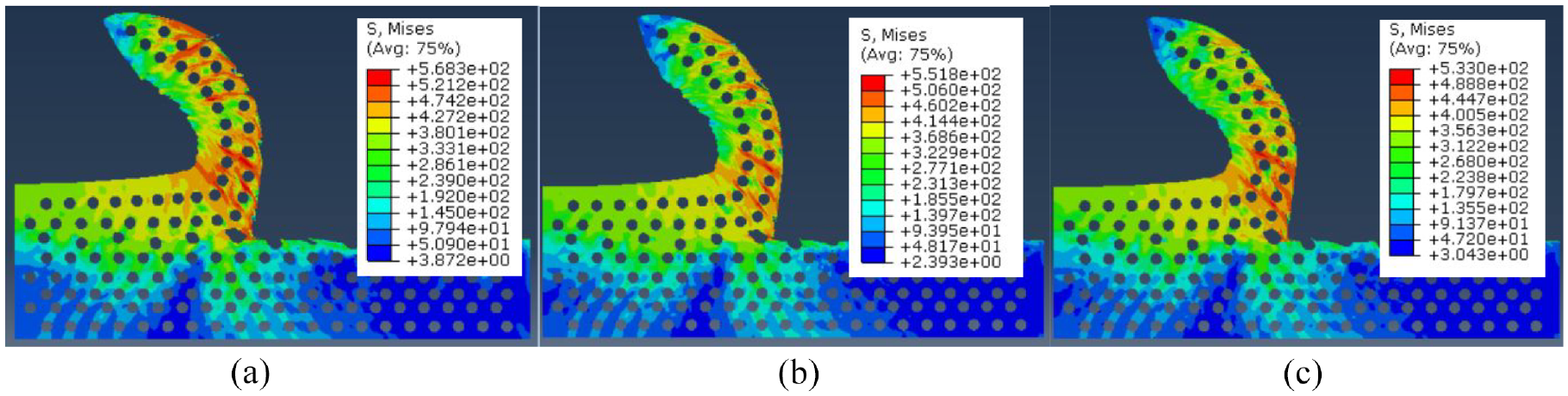
Mises stress contours at different cutting speeds (a) V = 24 m/min, (b) V = 60 m/min, (c) V = 100 m/min, f = 0.1 mm/rev, particle size = 23 µm, volume fraction = 20%.
The effects of cutting speed on the debonding and fracture of reinforced particles at the machined surface is shown in Figure 14. It is obvious from the figure that at low cutting speed there is more de-bonded particles as compared to the fracture particles at the machined surface. As the cutting speed increases from 24 to 60 m/min the number of de-bonded particles are reduced and most of the particles are fractured by the advancement of the cutting tool. With low cutting speed the engagement time between the cutting tool and reinforcement particle is larger which facilitates debonding. In contrast, as cutting speed increases, the interaction time decreases and the impact on the reinforcement particle is higher due to greater momentum of the tool which results in more particle fractures as depicted in Figure 14.

Machined surface characteristics at different cutting speeds (a) V = 24 m/min, (b) V = 60 m/min, f = 0.1 mm/rev, particle size = 23 µm, volume fraction = 20%.
Conclusions
The FE models developed using CZE and failure criterion for reinforced particles are able to simulate damage depth, particle debonding and fracture with reasonable degree of accuracy.
Damage depth is shown to decrease as particle size increases because particle spacing increases, resulting in reduced stresses at the machined surface.
Higher feed rates give rise to thick damage layers due to higher cutting and thrust forces. The high thrust forces on the flank face give rise to increased mechanical loads on the machined surface.
The cutting speed variations do not have any profound effect on the thickness of the damage layers. A slight reduction is observed with increased cutting speed due to softening of the matrix as a result of higher temperatures.
The influence of cutting speed on particle debonding and fracture at the machined surface can be simulated by the developed FE models. Low cutting speeds facilitate de-bonding whereas higher cutting speed give rise to more particle fracture at the machined surface.
Footnotes
Handling Editor: Chenhui Liang
Declaration of conflicting interests
The author(s) declared no potential conflicts of interest with respect to the research, authorship, and/or publication of this article.
Funding
The author(s) disclosed receipt of the following financial support for the research, authorship, and/or publication of this article: This research and APC was funded by the National Plan for Science, Technology, and Innovation (MAARIFAH), King Abdulaziz City for Science and Technology, Kingdom of Saudi Arabia, Award No. 13-ADV-971-02.