
Abstract
To analyze the cause and mechanism of oil mist escaping from the lower guide bearing during the operation of a turbine, the oil-gas mixture in the lower guide bearing was numerically simulated by using the VOF two-phase flow model and the SST turbulence model. The influences of different sealing clearances and speeds on the flow field and the oil-gas distribution in the oil tank were studied, and the escaping characteristics of oil mist were analyzed. The results show that increasing the clearance of the labyrinth seal will reduce the pressure difference between the inside and outside of the oil tank and reduce the driving force for the escape of the oil mist. However, increasing the clearance will increase the turbulence of the flow field, the number and volume of bubbles in the lubricating oil, which will lead to the uneven distribution of oil and gas and reduce the motion stability of the lower guide bearing. The change of speed will affect the normal use of the shaft-collar pump. High speed will aggravate the generation of bubbles in the oil tank and increase the possibility of cavitation in the lower guide bearing structure. In engineering practices, it is necessary to comprehensively consider factors such as oil mist escape phenomenon, economic benefits, process manufacturing and assembly, and adopt the lower guide bearing structure with a suitable labyrinth seal clearance.
Introductions
The escape phenomenon of oil mist from the lower guide bearings of a turbine has been discovered during the operation of hydropower stations around the world.1–4 The lubricating oil is atomized in the bearing chamber due to the temperature rise, and the oil mist escapes from the oil tank due to the internal and external pressure difference. The escape of oil mist is extremely harmful to the ecological environment, the safe operation of the power station, and the health of the staff working in the power station. Therefore, it is particularly urgent to solve the problem of oil mist escaping from the bearings of a power station.
As verified by scholars, the sealing performance and the sealing method of turbine bearing will greatly affect the escape of lubricating oil mist.5–9 Wu et al. 10 presents a computational fluid dynamic investigation quantifying the effects of labyrinth seal geometry and operating conditions on the rotor and stator circumferential friction factors. Brajdic Mitidieri et al. 11 studied the lubrication characteristics of sliding bearings based on the gas-liquid two-phase flow model. Walicka et al. 12 discussed the influence of both bearing surfaces roughness and porosity of one bearing surface on the pressure distribution and load-carrying capacity of a thrust bearing surfaces. Wasilczuk 13 presented lubricating systems of large tilting pad thrust bearings utilized in large, vertical shaft hydrogenerators in this paper. Akbarzadeh 14 studied the numerical calculation method of heat flow in the oil tilting-pad journal bearings of a vertical hydropower station, and used this method to analyze the effects of pad number, preload factor, pivot position and shaft rotational speed on the bearing lubrication performance. Canbulut et al. 15 simulated the hydrostatic bearing system through neural network research and obtained the amount of oil leakage. Chun and Khonsari 16 presented a wear analysis procedure and the wear calculation of journal bearings for a stripped-down single cylinder engine during start-up and coast-down. Wodtke et al. 17 studied the effect of thermal deformation of the bearing bush on the bearing performance, and verified the simulation results through experiments.
Regarding the numerical calculation and analysis of the oil-gas mixture in the bearing, Gertzos et al. 18 simulated the fluid domain of the oil film based on Fluent, and compared with the test results to verify the authenticity of the simulation. Jourak 19 used the slip grid for steady and unsteady calculations of the sliding bearing lubricants in turbulent flow. Li and An 20 established a calculation model for the plane thrust sliding bearing considering the micro-morphology based on the numerical simulation of rough surfaces. Aiping et al.21,22 took different bearing clearances as variable parameters and applied them in the rotor bearing model to study their influence on the rotor stability in the bearing chamber. Minghu 23 introduced cavitation and turbulence to the bearing model in CFD, and analyzed the influence of the micro-textured structure on the bearing capacity. Lijie et al. 24 optimized the load-bearing characteristics of the electric spindle based on ANSYS fluid-solid coupling calculation.
In terms of bearing load and cooling performance, McCarthy et al. 25 studied the influence of the surface material of thrust pad on the hydrodynamic lubrication of tilting pad thrust bearings from the aspects of oil film temperature and thickness. Shinkarenko et al. 26 studied the effect of surface deformation on the load-bearing performance, and found that surface micro-deformation can effectively improve the bearing capacity. Korolev et al. 27 studied the influence of different assembly conditions on the bearing capacity of ball bearings through experiments.
At the same time, many scholars have studied the influence of factors such as tip clearance and rotation speed on the internal flow pattern of fluid machinery. Shi et al.28–30 investigated the effect of tip clearance on the velocity distribution in a multiphase pump, the internal flow and velocity distribution characteristics in pump under different tip clearances were studied using experimental and numerical methods.Cao et al. 31 investigated the effect of blade pressure distribution on tip leakage flows based on three aspirated blades, including the one designed with conventional method and the other two designed with curvature induced pressure recovery. Han and Tan 32 studied the influence of speed on the energy performance of mixed-flow pumps, tip leakage flow, TLV structure, and pressure pulsation.
Based on the VOF two-phase flow model and the SST turbulence model, the influence on the oil-gas distribution and the flow field characteristics in the bearing oil tank by different sealing clearances and speeds were compared and analyzed for the turbine in Yuzixi Hydropower Station. The escaping mode and amount of oil mist were analyzed. The measures to inhibit the escape of oil mist were proposed after comprehensive consideration of the effect of different factors on the escape of oil mist in various hydro-generator sets.
Physical model and mesh generation
Computational domain model
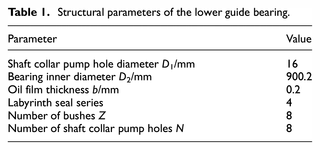
This research is based on the block-divided tile bearing structure with thin oil lubricated internal circulation in Yuzixi Hydropower Station, which is suitable for turbines under various heads, and has a simple structure and convenient installation. The structural parameters of the lower guide bearing are listed in Table 1.
Structural parameters of the lower guide bearing.
In order to comply with the real movement of the lower guide bearing and simplify the numerical calculation method, the oil-gas mixture with a thickness of 1 mm from the surface of the shaft collar, the spindle and other rotating parts is set as the rotating domain as shown in the Figure 1, and other fluid domain is set as the stationary domain according to the working principle of the shaft collar pump. The lower guide bearing with thin oil lubricated inner circulation is equipped with a collar structure. The collar is connected with the spindle and rotates with it. The lower guide bearing collar has eight collar pump holes at the bottom of the corresponding lower guide bearing bush. The center line of the collar pump hole has a 45° angle with the spindle axis on the shaft surface. In the oil tank of the lower guide bearing, lubricating oil is below the oil-gas interface, while air is above the oil-gas interface. During the rotation of the spindle, the shaft collar uses the centrifugal force of the lubricating oil in its cavity to generate a pressure head, forcing the oil to flow into the guide bush clearance through the shaft collar pump hole, thus providing circulation power for the lubrication and cooling oil in the lower guide bearing.

Lower guide bearing structure. 1: Cooler. 2: Bearing bush. 3: Shaft collar pump hole. 4: Shaft collar. 5: Oil retaining ring. 6: Spindle. 7: Oil-gas interface. 8: Labyrinth seal clearance. 9: Dynamic and static interface. 10: Rotating domain.
During the operation of the unit, the shaft collar drives the lubricating oil to circulate, while the lower guide bearing bush remains stationary. The oil film in the guide bush clearance generates heat due to the viscosity of the lubricating oil, which increases the oil temperature in the lower oil guide groove and vaporizes a small amount of lubricating oil, forming oil mist. The oil mist, driven by the pressure difference between the inside and outside of the oil tank, escapes from the cavity between the shaft collar and the oil retaining ring, causing the leak of the lubricating oil.
According to the structure data of the lower guide bearing of a vertical hydro-generator set, the calculation domain model for the oil-gas two-phase fluid is established, as shown in the Figure 2.
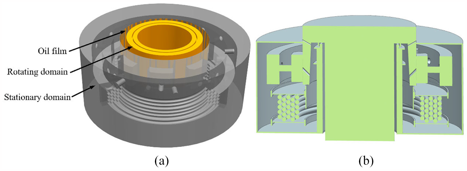
Lower guide bearing 3D model: (a) oil-gas two-phase fluid model and (b) structural section of lower guide bearing.
Mesh generation for the computational domain and working conditions
The quality of the grid plays a vital role in the accuracy of the calculation results. As the main load area, the oil film has a thickness of only 0.2 mm, so the rotating domain adopts the structural grid. Since the lower guide bearing includes complex structures, such as bearing bushes, coolers, shaft collars, venting flat holes, and labyrinth seals, the stationary domain adopts the non-structural grid. In order to ensure the quality of the grid and the accuracy of the connection between the nodes of the static and static interface in the static domain, the mesh encryption processing and adjustment are carried out on the static and static interface and the computing domain with small size. The following guide bearing oil system temperature is the standard, and mesh independent analysis is carried out for the lower guide bearing. Finally, the grid data with a grid number of 17,965,008 was selected for calculation, and the grids for the computational domain are shown in the Figure 3.
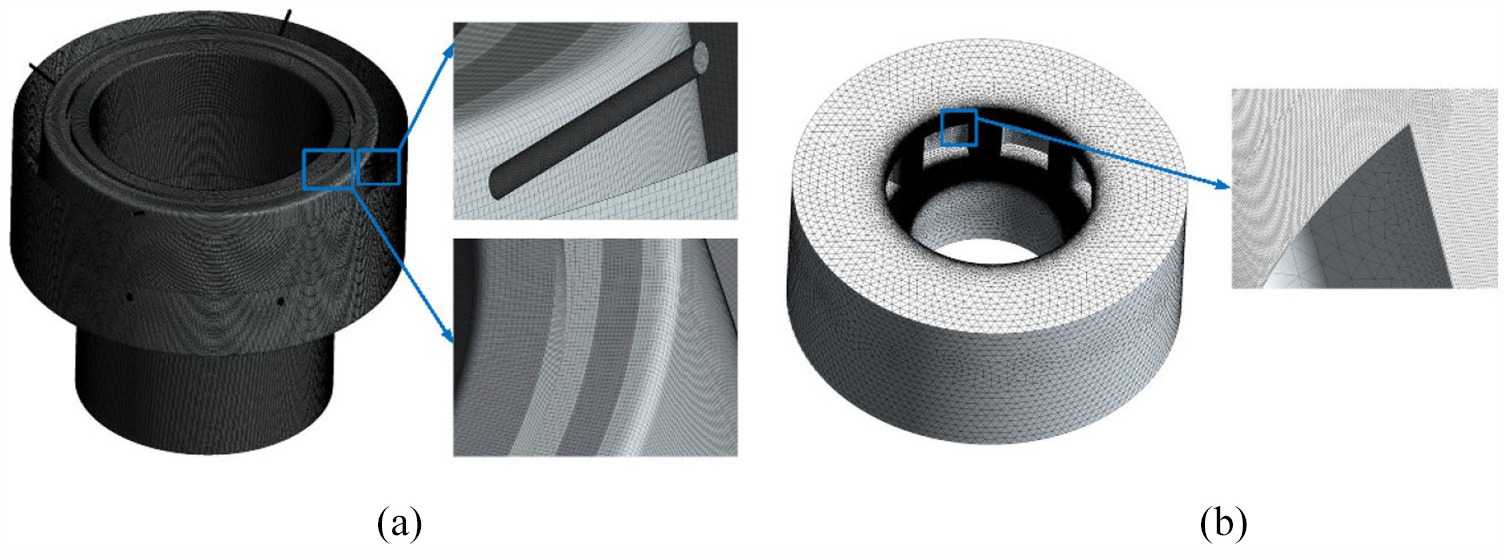
Rotational and static grids of lower guide bearing in numerical calculations: (a) rotating grid and (b) stationary grid.
In view of the characteristic parameters of different turbines, the influence of the labyrinth seal clearance and speed on the escape phenomenon of bearing oil mist is discussed, and the selected calculation conditions are listed in Table 2.
Calculation conditions.

Mathematical model and numerical method
Mathematical model
This paper mainly studies the two-phase flow of lubricating oil and air in the lower guide bearing of a hydro-generator set. Air and lubricating oil are distributed at the top and bottom of the oil tank, so the VOF two-phase flow model suitable for the conditions of clear interface between phases and significant impact of the interface on the flow field is adopted. The volume fraction and viscosity formula of the two-phase flow model are as follows:


where, α represents the phase volume fraction, ρ represents the density of each phase, kg/m3, and μ represents the viscosity of the phase.
As a rotating part, the shaft collar forms a dynamic and static connection with the guide bush. The influence of shear stress on the oil film must be considered, so the k-ω equation in the SST turbulence model is adopted. Its turbulent kinetic energy k and diffusivity ω are calculated by the following formula:


where, Gk represents the k production term of the turbulent energy; Gω represents the ω production term; Г k and Г ω represent the effective diffusion terms of k and ω respectively; Yk and Yω represent the turbulent dissipation terms of k and ω respectively; D ω represents the orthogonal divergent term; and Sk and Sω are user-defined source terms.
Numerical method
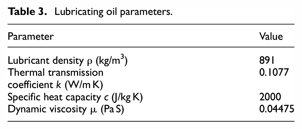
The lower guide bearing of the power station in this research uses the L-TSA46# turbine oil, and the parameters of the lubricating oil are listed in the Table 3. The cooler adopts the T2 copper tube (red copper tube) with a heat transfer coefficient of 377 W/m K.
Lubricating oil parameters.
When the lower guide bearing is working, the friction power consumption will be transformed into heat, so that the temperature of lubricating oil will rise. The basic conditions for achieving thermal balance in bearing operation are as follows: the heat generated by bearing friction in unit time H is equal to the sum of the heat taken away by lubricating oil flowing in unit time H1 and the heat emitted by bearing H2. Therefore, the calculation formula of friction heat of bearing per unit time is as follows:

Where, Ff represents the friction force in the fluid; u represents the circumferential velocity of lubricating oil.
The magnitude of frictional resistance (or shear force) in the fluid is proportional to the velocity gradient and contact area, and is related to the properties of the fluid, but independent of the pressure of the fluid. Its mathematical expression is:

Where, μ represents the dynamic viscosity of lubricating oil; A represents the contact area of the flow layer, taking 0.39517 m2; du/dy represents the velocity gradient, which represents the rate of change of flow velocity in its normal direction.
The heat taken away by the lubricating oil H1 is:

Where, Q represents the oil consumption can be obtained according to the coefficient of oil consumption; ρ represents the density of lubricating oil; c represents the specific heat capacity of lubricating oil; t2 represents the highest temperature of hot oil (assuming that the interface between bearing bush and oil film is the highest oil temperature heating surface); t1 represents the cold oil temperature.

Where, α s represents the surface heat transfer coefficient of the bearing, and αs = 140 W/(m2 K); d represents the diameter of bearing bush; B is the bearing bush width.
The setting of boundary conditions is a crucial step to solve the computational domain and obtain the correct simulation results. The spindle speed is set as n = 500 r/min, the temperature on the cooling pipe wall surface is set as 18.5°C, the interface between the oil film and the bearing bush is set as a 70°C heating surface, as the heat generated by the friction of the bearing bush, the ventilation hole and the oil outlet are set as openings, and the reference pressure is set as 1 atm.
The solution method of the numerical calculation affects the accuracy of the calculation results. The time derivative in this study adopts the first-order implicit formula, the difference format adopts the second-order precision, the numerical precisions of both the convection term and the turbulence term are high resolution, and the heat transfer model adopts the Total Energy.
Analysis of calculation results
The internal circulation structure of lubricating oil in the lower guide bearing is a semi-open structure, and the pressure difference between the inside and outside of the oil tank is used as a driving force to drive the gaseous oil mist inside the oil tank to escape, causing the leakage of the lubricating oil. The distribution of oil and gas in the oil tank reflects the fluctuation of the oil level and the characteristics of air bubbles in the tank during the operation of the hydro-generator set.
In order to verify the consistency between the numerical calculation results and the actual operation of the power station, the temperature of the lower guide bearing in the power station is monitored in real-time. The authenticity and accuracy of the numerical simulation are guaranteed by comparing the calculated heat transfer of the bearing with the actual temperature of the bearing. The monitoring point for the temperature of the lower guide bearing after stable operation is the oil-gas interface. The field investigation shows that the temperature remains at 45.5°C, the numerical results show that the temperature range of oil-gas interface is 42°C–47.5°C. As shown in Figure 4, it can be seen that the actual temperature of the lower guide bearing is consistent with the calculated result, which proves that the numerical calculation results are correct and reliable.

Temperature distribution of lower guide bearing: (a) original structure and (b) new structure.
Effect of labyrinth seal clearances on pressure characteristics and oil-gas distribution
The shaft collar speed is set to 500 rpm, and the labyrinth seals with five clearances of 4, 6, 8, 10, and 12 mm are selected. The pressure distribution on the characteristic axial plane when the hydro-generator set is operating stably is shown in Figure 5. The shaft collar is driven by the spindle to rotate at a high speed, the lubricating oil and air in the rotating domain are also driven to rotate, resulting in a pressure drop on both sides of the oil retaining ring in the rotating domain. The pressure difference inside and outside of the oil tank drives the oil foam and oil mist in the oil tank to escape from the cavity between the oil retaining ring and the shaft collar. Due to the synergistic effect of centrifugal force and gravity, the oil pressure increases with the increase of the radius, and the pressure is large near the outer edge at bottom of the oil tank. The part above the center line of the lower guide is mainly the air phase with a small pressure change gradient, and the part below is the lubricating oil phase with a uniform pressure change.

Pressure distribution on the axial plane of the lower guide bearing at different labyrinth seal clearances: (a) 4 mm, (b) 6 mm, (c) 8 mm, (d) 10 mm, and (e) 12 mm.
The pressure differences between the inside and outside of the oil tank at five types of labyrinth seal clearance are shown in the Figure 6. Due to the differences of density and viscosity between the oil and gas phases, the pressure difference gradually decreases as the seal clearance increases. The pressure difference is the largest at the 4 mm clearance, reaching to 10.9 kPa. The huge pressure difference will drive the oil mist in the oil tank to escape along the cavity, causing the leakage of lubricating oil.

Pressure difference between the inside and outside of the oil tank at different labyrinth seal clearances.
The oil-gas distribution on the characteristic axial plane when the hydro-generator set is operating stably is shown in Figure 7. Red represents the lubricating oil and blue represents the air. Due to the turbulent flow in the oil tank, the gas phase appears in the oil phase below the centerline of the lower guide, which will cause serious surge phenomenon. The large number of bubbles in the lubricating oil and their uneven distribution will affect the operating stability of the lower guide bearing structure, and accelerate the collision and impact of the lubricating oil, and accelerate the production of oil foam and oil mist. Under the combined action of the pressure difference and the centrifugal force, the lubricating oil climbs along the inner wall of the shaft collar. The labyrinth seal installed on the oil retaining ring of the lower guide bearing will prevent the lubricating oil from leaking through the cavity, which reduces the amount of leakage and the fluctuation amplitude of the oil-gas interface, and ensures the flow pattern in the oil tank and the stability of operation. The shaft collar pump hole at the five types of seal clearances is filled with lubricating oil, forming an oil film in the clearance with the bearing bush, which takes away the heat generated by the high-speed relative movement of the bearing bush and the shaft collar, and protects the bearing bush from being burnt out. With the increase of the seal clearance, the number of bubbles in the lubricating oil increases and the volume also increases, which makes the oil-gas distribution in the oil tank uneven and reduces the operational stability of the lower guide bearing.

Oil-gas distribution on the axial plane of the lower guide bearing at different labyrinth seal clearances: (a) 4 mm, (b) 6 mm, (c) 8 mm, (d) 10 mm, and (e) 12 mm.
Effect of speed on pressure Characteristics and oil-gas distribution
At present, vertical units are usually adopted for domestic and foreign hydro-generating sets, and the lower guide bearing is an important structure to ensure the stability of the vertical units. The parameters of the unit are different for different power stations. In this study, six working conditions with the sealing clearance of 8 mm and the speed from 200 to 700 rpm are selected. The rotation speed of the shaft collar is closely related to the pressure difference between the inside and outside of the oil tank. If the speed is too low, the lubricating oil cannot enter the clearance between the shaft collar pump hole and the bearing bush, causing the failure of the shaft collar pump, and the lubricating oil cannot transfer the heat generated by the friction between the high-speed rotating shaft collar and the bearing bush. If the speed is too high, the flow state pf the oil-gas mixture in the oil tank will be turbulent, which will increase the turbulent kinetic energy of the flow field and the fluctuating amplitude of the oil-gas interface, resulting in the unstable operation.
The distribution of pressure on the characteristic axial plane in the oil tank at different speeds is shown in Figure 8. When the turbine speed is lower than 300 rpm, the gravity is the dominant force on the oil-gas mixture inside the oil tank. The pressure is evenly distributed gradually increasing from the top to the bottom of the oil tank. The pressure in the shaft collar pump hole is small, and the oil tank cannot provide enough pressure head, disabling the function of the shaft collar pump. When the turbine speed increases from 400 rpm, both the centrifugal force and the gravity act on the oil-gas mixture. On the same radial plane, the pressure increases along the radius, and the lubricating oil enters the clearance between the shaft collar pump hole and the guide bush. When the turbine speed is higher than 600 rpm, the centrifugal force will be the dominant force on the oil-gas mixture, causing the uneven pressure distribution in the tank and on the same radial plane, which will lead to radial vibration of the spindle, reduce the stability of the unit and affect the operation safety of the power station.

Pressure distribution on the axial plane of the lower guide bearing at different speeds: (a) 200 rpm, (b) 300 rpm, (c) 400 rpm, (d) 500 rpm, (e) 600 rpm, and (f) 700 rpm.
The variation pattern of the pressure difference between the inside and outside of the oil tank at different speeds is shown in Figure 9. It can be seen that the speed is proportional to the pressure difference. When the turbine speed is lower than 300 rpm, the variation of the pressure difference is small, which cannot provide enough pressure head to the shaft collar pump hole. When the turbine speed is higher than 600 rpm, the pressure difference can ensure the operation of the shaft collar pump, and protect the bearing bush from being burned out during the high-speed operation.
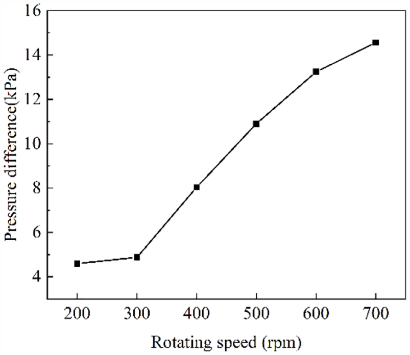
Pressure difference between the inside and outside of the oil tank at different speeds.
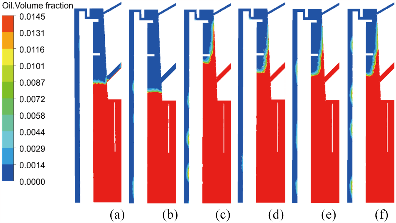
The distribution of oil and gas in the oil tank at different speeds is shown in Figure 10. Due to the difference in density and viscosity, the lubricating oil is at the bottom, and the air is at the top. When the turbine speed is lower than 300 rpm, the cavity between the inner wall of the shaft collar and the oil retaining ring is mainly filled with air, and the oil-gas interface is lower than the inlet of the shaft collar pump hole, so the lubricating oil cannot enter the shaft collar pump. When the turbine speed increases from 300 to 700 rpm, the oil-gas interface at both ends of the inner and outer walls of the shaft collar gradually reaches to an equilibrium, and the oil-gas interface in the cavity between the inner wall of the shaft collar and the oil retaining ring rises, so the shaft collar pump can work safely. At the same time, the labyrinth seal limits the continuous rise of the oil-gas interface due to the increase in speed. The oil-gas interface is stabilized at the first sealing teeth between the inlet of the shaft collar pump hole and the labyrinth seal, avoiding the oil rejection of the unit. However, during the increase of the turbine speed, bubbles appear in the oil tank, and their number and volume fraction are increasing. This is because at different speeds, the gravity of the oil-gas mixture inside the oil tank is the same, while the centrifugal force is constantly changing, which will lead to the fluctuation of the lubricating oil, causing impact and collision. The heat generated by the relative movement of the bearing bush and the shaft collar vaporize part of the lubricating oil to oil foam and oil mist. When the turbine speed is higher than 600 rpm, the oil-gas interface begins to tilt, and a large amount of air will be mixed into the lubricating oil, forming large-volume bubbles. The turbulent kinetic energy of the lubricating oil will increase with the number of bubbles, leading to serious surge phenomenon and poor stability. At the same time, the collapse of bubbles will cause cavitation in the bearing bush, collar and cooler structure, destroy the lower guide bearing structure, and produce strong vibration and noise, which will increase the complexity of the unit’s maintenance. Researches indicate that the lower guide bearing structure with labyrinth seal clearance is suitable for power stations with turbine speeds ranging from 300 to 600 rpm, which not only ensures the internal circulation of lubricating oil in the lower guide bearing, but also inhibits the escape of oil mist from the unit.

Oil-gas distribution on the axial plane of the lower guide bearing at different speeds: (a) 200 rpm, (b) 300 rpm, (c) 400 rpm, (d) 500 rpm, (e) 600 rpm, and (f) 700 rpm.
Analysis on the escaping characteristics of oil mist
Lubricating oil appears in the parts marked by the black lines, as shown in Figure 11, indicating that the oil mist has escaped from the bearing chamber and adhered to the cover of the lower guide bearing, the upper spider, and the surface of the spindle. Internal oil leakage and external oil leakage are the two main ways of oil mist escaping from the hydro-generating set. Internal oil leakage refers to the leakage of liquid oil droplets and gaseous oil mist from the cavity between the rotating part of the lower guide bearing and the oil retaining ring to the spindle. The external oil leakage refers to the leakage of the gaseous oil mist from the gap between the rotating part and the cover to the outside of the oil tank. The internal oil leakage is the main way of oil mist escaping from the internal circulation structure of the lower guide bearing, so the maximum volume fraction of the lubricating oil phase in the cavity between the spindle and the oil retaining ring is taken as the escaping amount of oil mist.

Distribution of oil mist escaping from the original structure of the lower guide bearing in the power station.
The escaping amount of lubricating oil in the escaping channel of the structure is amplified, as shown in Figure 12. It can be seen that under the conditions of the same rotation speed and different labyrinth seal clearances, the oil mist is subjected to the combined action of centrifugal force, gravity and viscous force, and escapes along the cavity between the oil retaining ring and the spindle, adheres to the inner wall of the oil retaining ring, and gradually slides to the bottom of the retaining ring. The baffle of the labyrinth seal keeps a small amount of oil mist gathering in the seal, which finally returns to the oil tank. With the increase of the sealing clearance, the escaping amount of oil mist gradually increases, and the maximum escaping amount can reach to 1.42%, as shown in Figure 14. The small sealing clearance can reduce the leakage of oil mist and ensure the normal operation of the unit. However, the small sealing clearance has high requirements on the manufacturing and assembly of large-scale hydraulic machinery, increasing the manufacturing costs, and reducing the economic benefits, which is not suitable for engineering applications. Therefore, it is necessary to comprehensively consider the escaping of oil mist and the economic benefit of the project, and select a labyrinth seal clearance suitable for the actual application of the unit.

Oil-gas distribution in the escaping channel of oil mist under different labyrinth seal clearances: (a) 4 mm, (b) 6 mm, (c) 8 mm, (d) 10 mm, and (e) 12 mm.
In order to explore the influence of different rotation speeds on the escape of oil mist, the lower guide bearing structure with a labyrinth seal clearance of 8 mm is selected, and the rotation speed varies from 200 to 700 rpm. The calculation results are shown in the Figure 13. When the rotation speed is lower than 300 rpm, the lubricating oil is less affected by the centrifugal force of the shaft collar, and the pressure difference cannot drive the oil mist and oil foam to escape from the cavity, and only a trace amount of gaseous oil mist escapes, which is generated by the friction between the bearing bush and the shaft collar. The escaping amount is less than 0.3%, which will not cause harm to the environment and the safety of the staff. As the rotation speed increases, the centrifugal force of the shaft collar on the lubricating oil is increased. The movement of the lubricating oil in the oil tank is intensified and disordered. As shown in Figure 14, the colliding and impacting of lubricating oil form oil foam and oil mist, resulting in an increase in the leakage of oil mist, and the maximum escaping amount reaches to 1.69%. The results show that the rotation speed has a direct impact on the escaping of oil mist and the changing of the oil-gas two-phase flow field inside the tank. The oil mist escaping phenomenon is obvious for turbines running in an extra high speed.
Oil-gas distribution in the escaping channel of oil mist under different speeds: (a) 200 rpm, (b) 300 rpm, (c) 400 rpm, (d) 500 rpm, (e) 600 rpm, and (f) 700 rpm.

The escaping amount of oil and gas under different labyrinth seal clearances and speeds.
Based on the analysis results of bearing oil mist leakage based on two parameters of rotating speed and labyrinth seal clearance, the working principle of oil system, the overall structure of bearing and the number of bearing bush are not changed. The labyrinth seal structure with 4-stage seal clearance of 6 mm is added on the inner surface of oil retaining ring and shaft collar, and four vent pressure holes with diameter of 8 mm are added on the top of shaft collar, A new structure of lower guide bearing is designed and applied to a hydropower station with a speed of 500 N/min. The application effect of the new structure of the lower guide bearing is shown in Figure 15. After 1 year’s modification and application of the structure of the lower guide bearing, through the measurement of the lubricating oil of the oil mist collection device and the observation of the oil mist escaping from the site of the power station, there is no obvious lubricating oil on the surface of the main shaft, the cover plate of the bearing chamber and the ground of the upper frame, and the leakage of the lubricating oil is improved. And the oil mist collection amount in the oil mist collection device is reduced. The results prove that the new type of lower guide bearing structure has obvious inhibiting effect on the escaping of oil mist, and can ensure the safe operation of the power station. The research and design method of the new type of lower guide bearing structure can be promoted in other power stations, and has a good economic benefit.

Distribution of oil mist escaping from the improved lower guide bearing structure.
Conclusion
The escaping of oil mist from the lower guide bearing is a complicated phenomenon, which is closely related to the labyrinth seal clearance of the lower guide bearing and the rotation speed of the turbine. The suitable labyrinth seal structures should be adopted to inhibit the escape of oil mist based on actual power station parameters. Based on the VOF two-phase flow model and the SST turbulence model, the influences of the labyrinth seal clearance and speed on the escaping of oil mist and the flow field of lubricating oil in the lower guide bearing are studied. The calculation results of heat transfer and the numerical results are compared to verify the accuracy of the calculation. The following conclusions are obtained:
The labyrinth seal clearance has an obvious influence on the pressure difference between the inside and outside of the oil tank. Increasing the clearance will lower the pressure difference and reduce the driving force for the oil mist to escape. However, increasing the clearance will aggregate the turbulence of the flow field, increase the number and volume of bubbles in the lubricating oil, making the oil-gas distribution uneven.
When the rotation speed is lower than 300 rpm, the shaft collar pump will lose its function, the lubricating oil cannot enter the shaft collar pump hole, and the bearing bush cannot be lubricated. When the speed is higher than 600 rpm, the pressure gradient in the oil tank changes unevenly, the flow becomes turbulent, and the impact and collision of the lubricating oil accelerate the formation of oil mist. High speed will increase the number of bubbles in the oil tank, and the collapse of bubbles will lead to cavitation, damaging the bearing structure, and causing vibration and noise.
The pressure difference between the inside and outside of the oil tank and the labyrinth seal clearance are the direct factors influencing the escaping of oil mist. The small labyrinth seal clearance and the low-pressure difference have the most significant inhibitory effect on the escaping of oil mist. In engineering practice, it is necessary to comprehensively consider factors such as oil mist escaping phenomenon, economic benefits, manufacturing and assembly, and adopt a suitable labyrinth seal clearance for the lower guide bearing structure.
Footnotes
Handling Editor: James Baldwin
Declaration of conflicting interests
The author(s) declared no potential conflicts of interest with respect to the research, authorship, and/or publication of this article.
Funding
The author(s) disclosed receipt of the following financial support for the research, authorship, and/or publication of this article: National Natural Science Foundation of China (Grant No. 51273172) and Sichuan Provincial Science and Technology Department Horizontal Commissioned Science and Technology Project(Grant No. 52190119000Z).