
Abstract
The pressure loads acting on the teeth of a labyrinth seal are usually not uniform. Sometimes, one tooth would take almost half of the total pressure difference, which is detrimental to the teeth’s working life and sealing effect. Therefore, the estimation of maximum pressure load on the teeth is helpful to design a sound structure of labyrinth seal. This article analyzes the influence of teeth number, boundary condition, clearances, and structure parameters on maximum pressure loads of labyrinth seal teeth in low pressure ratio conditions (PR≤ 0.5, PR = Pout/Pin). Both the computational fluid dynamics model and test results show that teeth number and pressure load are main factors influencing the maximum pressure load on teeth. Finally, a fitting equation is given to estimate the maximum pressure load on labyrinth seal teeth and its results are in good agreement with the computational fluid dynamics model.
Introduction
The labyrinth seals are important annular gas seals in turbomachines.1–3 As traditional annular gas seals, their major advantages are that they can be used for higher pressure gradients compared with other seals, like brush seals and finger seals.4,5 Labyrinth seal is most typically used as impeller seals, shaft seals, and balance piston seals in centrifugal compressors. In centrifugal compressors, its working efficiency can be raised by 2% if the seal clearance can be reduced by 50%. 6
The efficiency of labyrinth seal is determined by the values of its groove geometry, clearance, and teeth number. In terms of theoretical study, the basic principles of operation can still be described by the methods in the study by Martin 7 and Childs and Scharrer.8,9 Today, based on them, the computational fluid dynamics (CFD) methods are used to calculate flow behavior of labyrinth seal.10,11 Numerical calculation can give a clear visual display of the results.12–14 In experiments, labyrinth seal has been put to more severe conditions, such as greater pressure differential and higher rotational speed in recent years.15,16
Generally, leakage is the main factor in evaluating the sealing performance of labyrinth seal design. However, insufficient researches have been conducted in the estimation of the maximum pressure load on labyrinth seal teeth in the process of engine design. This problem is particularly serious for labyrinth seals made of polymer materials, which are often used to reduce wear. These polymer materials deform more easily than traditional metals in high pressure difference. Hence, this study on the maximum pressure load of labyrinth seal teeth is helpful to know their stress and deformation conditions.
The earliest research on pressure distribution of labyrinth seal dated back to the early twentieth century.7,17 Their results showed that the pressure load increased gradually from the first tooth to the last one, and the last tooth carried the maximum pressure load. However, their research did not consider heat exchange and assumed that the carry-over coefficients were the same for all teeth.
Suryanarayanan and Morrison 18 studied the influence of flow parameters on carry-over coefficient of labyrinth seal. Their results showed that the maximum pressure load occurred on the first tooth and remained constant on the other teeth. Their explanation was that there was an entrance effect caused by the difference between the upstream flow of first tooth and its inside cavity. 18 Moreover, their model is only applicable to incompressible flows.
Other researches19,20 also indicated that the maximum pressure load occurred on the first tooth, but they offered a different explanation which is applicable to high pressure ratio and compressible flows. Their explanation goes like this: the first tooth has a high flow contraction because there is no upstream “carry-over” effect. Meanwhile, fluid turbulence intensity decreases along the flow, therefore the kinetic energy loss decreases as the fluid flows through each cavity.
Dogu et al. 21 discussed the effect of pressure ratio on the pressure drops on each tooth. Their results show that the highest pressure load was on the first tooth (the first tooth carried about 62% of total pressure load) when the pressure ratio was 0.67. However, the last tooth would carry the maximum pressure load in low pressure ratio conditions. For instance, the first tooth carries about 46% of total pressure load for PR = 0.28 (PR = Pout/Pin). They thought that the large Mach number of the flow in last clearance was the main reason for the last tooth to carry the highest pressure load in low pressure ratio conditions. 21
J Jiang et al. 22 studied the uniformity of pressure load on labyrinth seal teeth. The results showed that the pressure load on the teeth was not completely uniform. The test results showed that the first tooth carried the maximum pressure load for PR > 0.5. However, the maximum pressure load occurred at the last tooth for PR≤ 0.5.
The above researches all indicate that the pressure load on labyrinth seals is not uniform. In recent years, labyrinth seals are more frequently used in lower pressure ratio conditions (PR≤ 0.5). Meanwhile, for high pressure ratios, the maximum pressure load on the teeth is too small to have any effect on the deformation of teeth. However, low pressure ratio (0.2 ≤PR≤ 0.5) and great differences of pressure loads will force a certain tooth in the seal to suffer an extreme loading condition. Therefore, in labyrinth seal design, estimation of the maximum pressure load on the teeth is helpful to make a desirable structure of labyrinth seal. Recent researches are based on the CFD method to calculate the maximum pressure load on labyrinth seal teeth. This article studies the influence of teeth number, boundary condition, and clearances on the maximum pressure load of labyrinth teeth for the pressure ratio range 0.2–0.5. And it proposes a fitting equation dependent on the pressure ratio and teeth number to estimate maximum pressure load on labyrinth seal teeth.
Theoretical researches and experiment system
CFD model
As shown in Figure 1(a), a four-teeth straight-through labyrinth seal is adopted. The structural parameters of the seal are given in Table 1. The three-dimensional (3D) CFD model and a structural grid for the labyrinth seal are generated in ANSYS ICEM CFD. The mesh independence has been verified to ensure accuracy, and a fine mesh density is used in the region of clearance and grooves, as shown in Figure 1(b). The average value of y+ is

Size of labyrinth seal and mesh of flow field: (a) size and flow field of labyrinth seal, (b) local mesh of flow field, (c) mesh independence (PR = 0.2, P4 = 0.1 MPaA), and (d) leakages under various PR.
Labyrinth parameters.

The mass conservation equation, the momentum conservation equations, and the energy conservation equations (equations (1)–(3)) are numerically solved with the CFD software Fluent

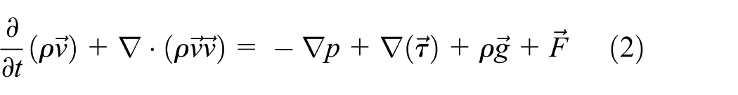

where ρ is the density, t is time,
The airflow is assumed to comply with the ideal gas law, and the compressibility of gas is also considered

where p is the pressure, Mw is the molecular weight of the gas, R is the universal gas constant, and Tem is the temperature.
The Reynolds number of the flow in the tip clearance of the four teeth on a straight-through labyrinth seal varies from about 2000 to 7700, so the standard k-ε turbulence model is adopted. In the standard k-ε model, turbulence kinetic energy k and its rate of dissipation ε are obtained from the following transport equations

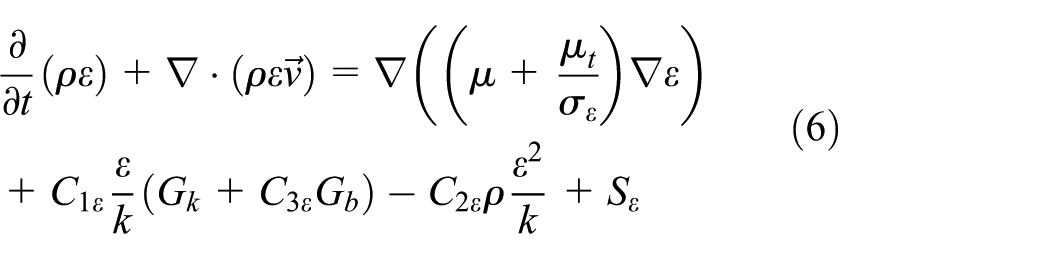
In these equations, Gk represents the generation of turbulence kinetic energy due to the mean velocity gradients, Gb is the generation of turbulence kinetic energy due to buoyancy, and YM represents the contribution of the fluctuating dilatation in compressible turbulence to the overall dissipation rate. μt (= ρCμ k2/ε) is the turbulent viscosity. C1ε(= 1.44), C2ε (= 1.92), C3ε (= 1.3), and Cμ (= 0.09) are constants. σk (= 1.0) and σε (= 1.3) are the turbulent Prandtl numbers for k and ε. Sk and Sε are source terms.
Maximum pressure load on the tooth
As shown in Figure 1, pressure of the ith groove is defined as

Substituting the relative pressure

where the total pressure difference ΔP and pressure ratio PR can be obtained by equations (9) and (10)


According to formulas (7)–(10), the pressure on each tooth can be obtained by

Equation (11) indicates that pressure load on the tooth is dependent on


where
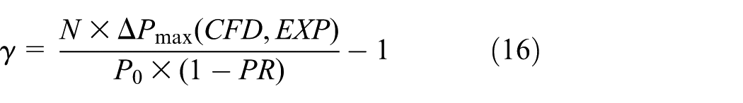
Consequently, the maximum pressure load on the tooth can be written as

where the coefficient

Equation (15) shows that the max pressure load on the teeth relates to the coefficient
Experiment testing system
Our experiment testing system can measure the outlet leakage and the pressure at each groove. Measurable leakage ranges and the maximum upstream pressure are 0–150 Nm3/h and 0.5 MPa, respectively. To measure the pressure of each groove, three grooves are connected to pressure sensors by tubes illustrated in Figure 2(a). Therefore, the pressure difference between the two sides of a groove represents the pressure load on the tooth. As shown in Figure 2(b), the test end consists of the following parts: test cavity, pressure sensors, and temperature sensor. The experimental measurement error of labyrinth seal pressure is 1% of the measured value. High pressure gas passes into cavity from two sides of the test cavity at the same time, which is beneficial for the stability of inlet pressure.
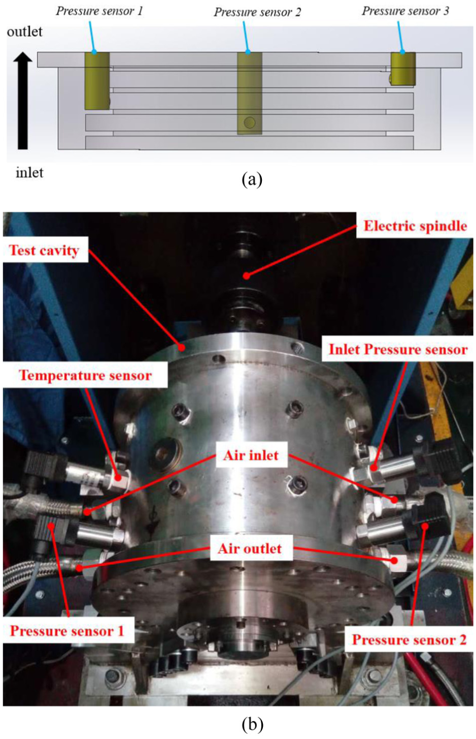
Labyrinth seal test system: (a) labyrinth seal and (b) photograph of test end.
Results and discussion
In order to obtain coefficient
Moreover, the coefficient
As shown in Figure 3, the vertical error stands for pressure ratio error, and it is calculated by inlet pressure in the experiment. In high pressure ratio conditions, the inlet pressure is very low, close to the lowest pressure to control the valve, which leads to a relatively large error for its value. However, gas valve can be readily controlled at the low pressure ratio, and the inlet pressure error is small. The horizontal error stands for the pressure load error, and it is calculated by the pressure value in each cavity in the experiment. For low pressure ratio conditions, the larger gas velocity results in greater sensor measurement error.
CFD and EXP results
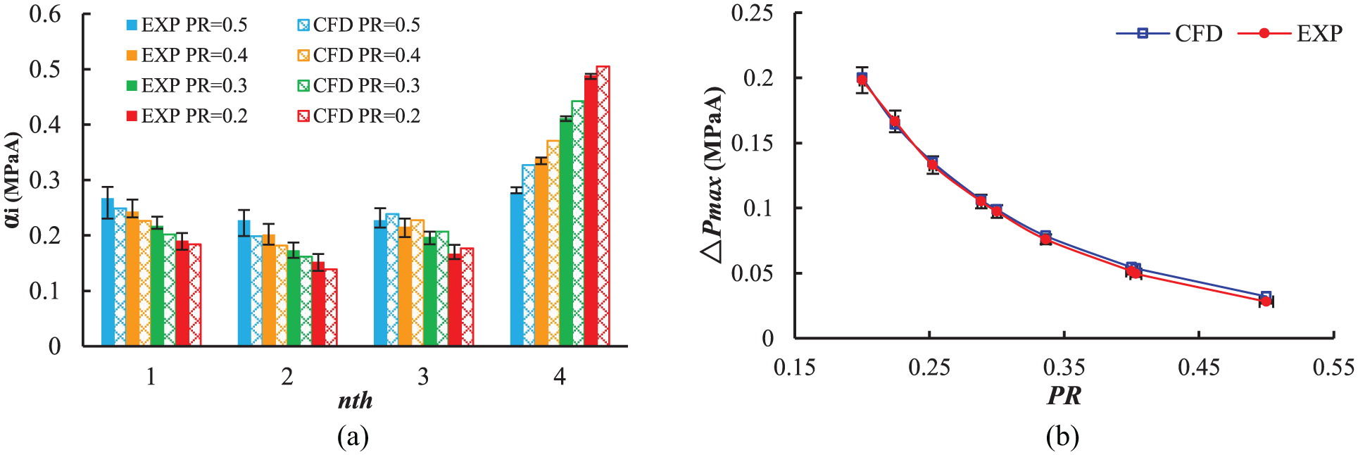
When the outlet pressure is constant
The maximum pressure load on the teeth is shown in Figure 3(b), and the maximum errors about CFD and test results are 11%. Therefore, with decreasing pressure ratio, the maximum pressure load on teeth is generally increasing. This means that the last tooth will carry more pressure load as the pressure ratio decreases.
Teeth number
The coefficient

PR versus coefficient
Figure 4 illustrates a function relation between pressure ratio and coefficient
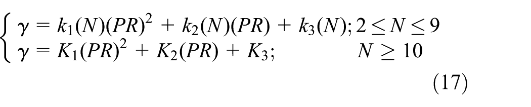
where the coefficients k1, k2, and k3 are dependent on teeth number N. For 2 ≤N≤ 9, the coefficient k is

For N≥ 10, the teeth number has no effect on coefficient

In Figure 5, the CFD results show that the coefficient

PR versus coefficient γ (point-CFD; curve-fitting).
Boundary conditions
The boundary conditions include inlet pressure, outlet pressure, and pressure ratio. Equation (10) shows that if two of these parameters are known, the third can be obtained. It means that there are only three cases in operating conditions. It should be noted that the case in which P0 is a constant and PR is a variable is less used in practical situations, thus it is not discussed here.
The case in which P4 is a constant and PR is a variable is shown in Figure 4. Therefore, there is only one case that should be considered, that is, the pressure ratio PR is constant (PR = 0.2, 0.3, 0.4). The relationship between outlet pressure P4 and coefficient

Outlet pressure versus
Tooth clearance
Tooth clearance is one important parameter of the labyrinth seals.23,24 Some researches show that clearance is the main reason for leakages. Therefore, the effect of clearance on the coefficient

PR versus
Structural parameters
Figure 8 shows the influence of various structural parameters on coefficient
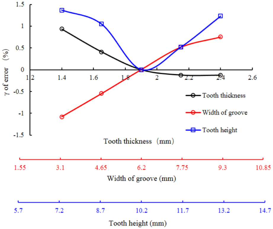
Various structure parameters versus coefficient
Fitting method calculation of maximum pressure load
From the above analysis, the maximum pressure load on the teeth is only dependent on inlet pressure, pressure ratio, and teeth number. The detailed flow diagram of the proposed method is illustrated in Figure 9, and the results of calculation are shown in Figure 10. In addition, the maximum pressure loads on labyrinth seal’s teeth can be obtained by Figure 10.
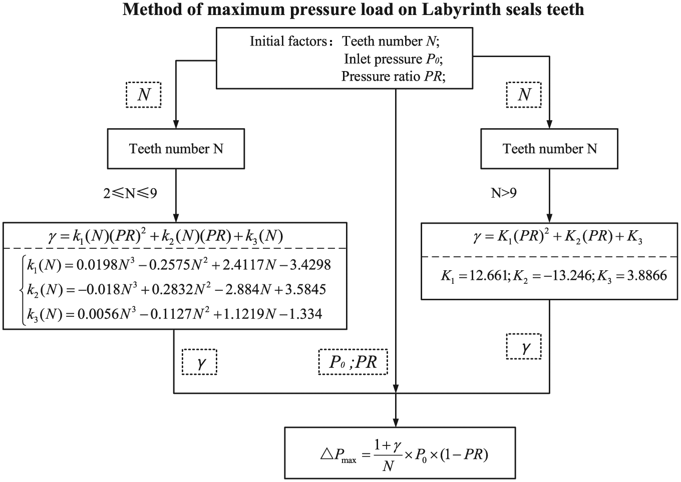
The flow diagram of the method.

Fitting method calculation of maximum pressure loads.
Conclusion
The pressure loads on the labyrinth seal teeth are not uniform and the last tooth carries the maximum pressure load in low pressure ratio conditions (PR≤ 0.5). Based on the CFD and tests, this study proposes a mathematical analysis formula, which can calculate the maximum pressure load on each tooth of labyrinth seal. The results show that the maximum pressure load on the teeth is dependent on boundary condition, teeth number, and coefficient
Furthermore, the effect of teeth number, boundary conditions, clearances, and structure parameters on the coefficient
Footnotes
Handling Editor: Kai Bao
Declaration of conflicting interests
The author(s) declared no potential conflicts of interest with respect to the research, authorship, and/or publication of this article.
Funding
The author(s) disclosed receipt of the following financial support for the research, authorship, and/or publication of this article: The authors are grateful to National Basic Research Program of China (973) (Grant No. 2012CB026003) and National Science and Technology Major Project (No. 2011ZX02403-4-3).