
Abstract
The pressure loads acting on the teeth of a labyrinth seal could differ significantly. Sometimes, one of the teeth would take almost half of the total pressure difference. This article makes an analysis of the influence of pressure ratio and seal geometry on the uniformity of pressure loads on labyrinth seal teeth. Therefore, a coefficient to evaluate the uniformity of pressure loads on the teeth is presented. The computational fluid dynamics model and test results show that the pressure ratio is the main important factor that affects the uniformity of pressure loads on the teeth. In order to improve the uniformity of pressure loads on teeth, the non-uniform seal geometry parameters are analyzed. In addition, it is found that the non-uniform clearances and groove width play positive roles in improving the uniformity of pressure loads on the teeth.
Keywords
Introduction
Labyrinth seals are widely used as rotating seal in turbomachines such as aircraft engine and gas/steam turbines.1–3 As traditional non-contact seals, labyrinth seals have their major advantages, for instance, capability of running in extreme operating conditions (high temperatures, high-pressure gradients, and high rotor circumferential speeds) and easy manufacture and long lifespans. A series of regular throttling gaps and expansion grooves for the flow is formed in labyrinth seal teeth. Due to the viscosity of the fluid and the gradual throttling effect of energy conversion, the leakage resistance is realized.
The pressure distribution is the important factor in analyzing the leakage performance of labyrinth seals. Because flow resistance in each tooth is different, the energy dissipation efficiency and pressure distribution are also different on each cavity. In addition, the pressure loads on the teeth not only indicates pressure distribution but also reflects stress conditions on the tooth. Therefore, the study on leakage characteristics demands full understanding of the pressure loads on the teeth. In the past century, researchers’ understanding of the pressure loads in labyrinth seals experienced several major changes.
The earliest research on pressure distribution of labyrinth seal dated back to Martin 4 and Egli. 5 They tried to obtain the pressure distribution of labyrinth seal using thermodynamic equations. Their results show that the pressure load increases gradually from the first tooth to the last one. However, Martin neglected the effect of carry-over kinetic energy. Egli made some modification of the basic equation put forward by Martin by incorporating an experimentally determined flow coefficient to account for the kinetic energy carry-over. But he still neglected heat exchange and assumed that the carry-over coefficients are the same for all the teeth.
Suryanarayanan and Morrison 6 discussed the flow parameters influencing carry-over coefficient of labyrinth seal. His report shows that pressure drop across each tooth remains constant except the first one, where there is an entrance effect due to the fact that the upstream flow of the first tooth is different from the flow inside each cavity. But his model is only applicable to incompressible flows.
Other researches7–9 indicate that pressure load decreases gradually from the first to the last tooth with high pressure ratio
Dogu et al. 10 gives a more comprehensive analysis of the pressure drops on the teeth of the labyrinth seal. He discovered that the highest pressure load is on the first tooth, when the pressure ratio was 0.67. With decreasing pressure ratio, it moves to the last tooth. The first tooth carries about 62% of total pressure load for PR = 0.67, while it drops to 37% for PR = 0.28. At the same time, the percentage carried by the last tooth changes from 10% to 46%. He considered that the larger Mach number of the flow in last clearance is the main reason for the fact that the last tooth carries the highest pressure load in lower pressure ratio.
The above researches all show that the pressure drops on the teeth are not uniform. In recent years, labyrinth seals are used in higher pressure difference, that is, lower pressure ratio, more frequently. High pressure difference and terrible uniformity of pressure loads will force a certain tooth in the seal to suffer an extreme loading condition. Especially, when polymer materials are used as labyrinth seals reduce rubbing, 11 tooth deformation is far more likely to occur than metal materials due to the lower elastic modulus of polymer materials. Thus, the analysis on uniformity of pressure loads on labyrinth seal teeth is much more significant. This article studies the influence of pressure ratio and seal geometry to achieve a more in-depth understanding of the pressure loads on labyrinth seal teeth.
Theoretical researches and experiment system
Computational fluid dynamics model
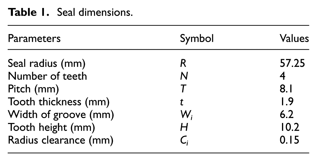
Our study uses a four-teeth straight-through labyrinth seal, as shown in Figure 1(a). The dimensions of the seal are listed in Table 1.

Size of labyrinth seal and mesh of flow field: (a) size and flow field of labyrinth seal, (b) local mesh of flow field, (c) mesh independence (PR = 0.2, P4 = 0.1 MPa), and (d) leakages under various PR.
Seal dimensions.
The mass conservation equation, the momentum conservation equations, and the energy conservation equations are numerically solved using the computational fluid dynamics (CFD) software Fluent. Due to the axisymmetry of the fluid, the model also can be simplified to two dimension in simulation. The pressure ratio is defined as outlet pressure divided by inlet pressure.
A structural grid for the labyrinth seal is generated in ANSYS ICEM CFD, and the mesh density is far greater in the region of clearance than in seal grooves, as shown in Figure 1(b). As shown in Figure 1(c), the mesh independence has been verified to ensure accuracy. The results show that the leakage error remains at 3%, when the number of cells is larger than 200,000. Therefore, the final calculation number of cells is 200,000. The average value of y+ is
The airflow is assumed to comply with the ideal gas law, and its compressibility is also considered. The Reynolds number of the flow in the clearance of the four teeth on a straight-through labyrinth seal varies from about 2000 to 7700; therefore, standard k–ε turbulence model is adopted. The standard wall functions are adopted to near-wall treatment.
The coefficient used to define the uniformity of pressure load on the teeth
The total pressure difference △P is

The average pressure in each groove is defined as

Substituting the relative pressure

The inlet pressure
The coefficient


where
The smaller coefficient
Experiment system
To verify the validity of the numerical calculation, an experiment system is built. In addition, the system can measure the pressure of groove, inlet pressure, inlet temperature, and outlet leakage at the same time. The test system consists of the following parts (shown in Figure 2): main test chamber, electric motor spindle, temperature sensor, pressure sensors, and leakage measurement system. In order to measure the each pressure of groove, three grooves are connected to the pressure sensors by hoses.

Labyrinth seal test system: (a) labyrinth seal test system, (b) labyrinth seal, and (c) photograph of test end (end cover is not installed).
Results and discussions
The pressure drops and velocity increases in the axial direction along the middle line are plotted in Figure 3. As shown in Figure 3(a), the curve shows that pressure gradually drops from the first to the last tooth with the various pressure ratios. The maximum pressure drops occurs at the first clearance with high pressure ratios, and as the pressure ratio decreases, it begins to occur at the last clearance. As shown in Figure 3(b), for instance, for pressure ratio PR = 0.2, the velocity contour shows that gas is compressed, and the velocity will increase at the clearance. After the clearance, gas escapes quickly from the clearance to the grooves, and the vortex is observed in the groove. In addition, the curve indicates that gas velocity increases in the clearances and decreases in the grooves, but overall the velocity gradually increases from the first to the last tooth.

Profile of (a) pressure drops and (b) velocity increases at midline of clearance
The change of relative pressure
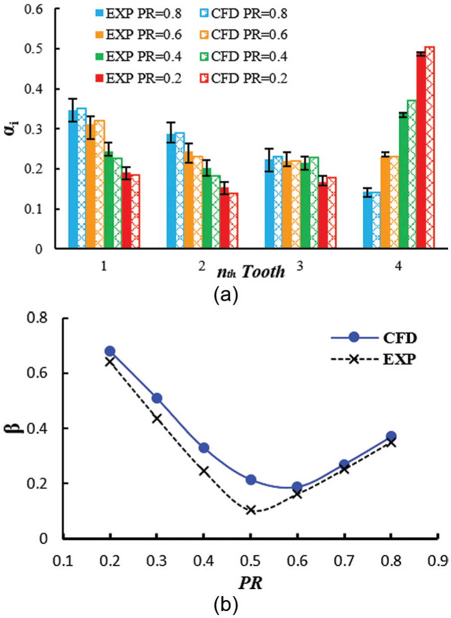
Coefficient of CFD and EXP results
The coefficient
The influence of tooth parameters on coefficient of uniformity
In this part, an extreme condition, where PR = 0.2, is chosen, to discuss the clearance and groove width about the coefficient
Non-uniform clearances
To study the influence of clearances on pressure load by changing only one clearance while other clearances remain the same. Others parameters are given in Table 1. The clearance range is from 0.1 to 0.25 mm.
Figure 5 shows that with the increasing Ci, the upstream pressure of tooth

Clearance versus tooth pressure load on each tooth
Increasing C4 can reduce the pressure load on the last tooth

Comparison between optimal and origin
Non-uniform groove width
In this part, the same method is applied to groove width. That is, as clearance is modified, the groove width range is changed from 3.1 to 12.4 mm. Other parameters are also kept at their baseline case values as in Table 1.
Figure 7 shows that the groove width Wi is proportional to pressure

Groove width versus tooth pressure load on the tooth
Because smaller groove width results in larger leakages,14,15 the groove width W1 should be increased. Thus, a new set of non-uniform groove widths are obtained from calculation: W1 = 12.4 mm, W2 = 9.3 mm, W3 = 3.1 mm. As Figure 8(b) shows, it can also be seen that the coefficient

Comparison between optimal and origin
Conclusion
Based on the CFD and tests, this study analyzes the influence of pressure ratio on the uniformity of pressure loads on the labyrinth seal teeth and puts forward a coefficient
In order to improve the uniformity of pressure loads on teeth, the non-uniform seal geometry parameters are analyzed. Research shows that the non-uniform clearances and grooves width can help improve the uniformity of pressure load on teeth. The results show that pressure load on the tooth decreases with its clearance. Based on what has been found, an optimal non-uniform clearance design (C1 = 0.12 mm, C2 = 0.12 mm, C3 = 0.15 mm, C4 = 0.18 mm) is given, the coefficient
Footnotes
Academic Editor: Kai Bao
Declaration of conflicting interests
The author(s) declared no potential conflicts of interest with respect to the research, authorship, and/or publication of this article.
Funding
The author(s) disclosed receipt of the following financial support for the research, authorship, and/or publication of this article: The authors are grateful to National Basic Research Program of China (973) (grant no. 2012CB 026003), National Science and Technology Major Project (no. 2011ZX02403-4-3).