
Abstract
The bellows of the vehicle are vulnerable to noise because of the low transmission loss among the components. Therefore, in this study, we modified the thickness and the structure of the bellows to improve transmission loss. Based on the impedance tube test, the transmission loss of the silicon rubber specimen – the main material of the bellows – was analyzed; the results confirmed low transmission loss in the low-frequency region. An analysis of the natural vibration model of the simple model indicated that in the low-frequency region of the bellows, a number of vibrations occurred because of the vibration of the outer and inner components. Accordingly, to improve transmission loss, the improvement introduced by varying the thickness was analyzed, and the results confirmed that the noise performance improved by more than 3 dB for a thickness of 3.5 mm in the double-layer structure. In addition, the transmission loss improved in the low-frequency region after acoustic-structure coupling analysis was performed based on a simple model. To compare the actual performance between the existing and improved bellows, a noise comparison test was performed. The test results confirm that the existing noise reduction index improved by 3 dB from 30 to 33 dB when the thickness was increased to 3.5 mm; in the frequency domain, the highest noise performance was improved with an improvement of 5.6 dB at 160 Hz.
Introduction
Railroad vehicles operate under various driving environments such as open areas, tunnels, bridges, and noises generated at this time enter the vehicle through the vehicle body.1,2 In particular, railway vehicles are exposed to noises of complex and various frequency characteristics owing to the noise generated in the various driving environments. Noise tends to flow into components with the lowest transmission loss, and therefore, to minimize such noise effectively, it is necessary to increase the transmission loss of the vehicle body. To this end, the bellows of a railroad vehicle are components vulnerable to noise because of their low transmission loss among the other components of the vehicle. The main reason for this low transmission loss is attributed to the silicone rubber used to fabricated it to facilitate contraction and expansion during the curved driving of the vehicle. Silicone rubber has the characteristic of low weight per unit area, which considerably affects transmission loss, and it is significantly lower than that of aluminum materials manufactured for the vehicle body. However, studies on improving the transmission loss for bellows of railway vehicles are lacking.
Research on the improving transmission loss of railway vehicles has been focused on the vehicle body. In particular, honeycomb panels of various types have been investigated to increase transmission loss and reduce the vibration of railway vehicles.3–5 Thus, transmission loss for the vehicle body was predicted, and a study was conducted on floating floor structures to lighten the vehicle body to improve vehicle performance. 6 Another study was conducted to analyze the effect of transmission loss by examining the boundary conditions of the vehicle body. 7 In addition, the use of viscoelastic materials was investigated to reduce the noise and vibration of the vehicle body. 8 In general, studies on improving the transmission loss of railroad vehicles have been conducted for a vehicle body made of aluminum, and therefore, their consideration of the bellows made of silicon rubber is limited.
Noise studies on the bellows of railroad vehicles were conducted by focusing on the external noise generated by the vehicle. It was confirmed that high noise was generated in the bellows when the railway vehicle traveled at high speeds9–11; this was attributed to the generation of a large amount of noise caused by the turbulent flow around the vehicle when driving at high speed. These noises are generated in the low-frequency range, and they tend to increase when driving through a tunnel. 12 Furthermore, it was confirmed that indoor noise can be significantly reduced when side barriers are installed at the bellows to minimize the inflow of vehicles. 13 However, research on improving noise performance by changing the structural body of the bellows of railway vehicles is insufficient.
Research on the structure of bellows in railways has been performed to improve the durability of materials composed of silicone rubber. 14 In this study, the analysis of various deformations that can occur when the vehicle is driven in a curved line was analyzed by considering the nonlinearity of silicone rubber. Furthermore, considering that the bellows of the vehicle are devices that connect vehicles, an analysis of the suspension system for the related part was performed. 15 Thus, research on increasing the transmission loss of bellows of railway vehicles in terms of noise remains insufficient.
Therefore, this study aimed to improve the transmission loss of bellows by changing the structure of the connecting membrane. First, the transmission loss of the silicon rubber specimen and the main material of the connecting membrane was analyzed based on the results of the impedance tube test. The results confirmed that the transmission loss in the low-frequency region was low for the connecting membrane. Furthermore, based on a two-dimensional simple model, we analyzed the natural frequency and mode to analyze the cause of noise generation in the bellows. To derive a method for improving the transmission loss of the bellows, the transmission loss analysis was performed for various thickness change models. To analyze the transmission loss of the proposed model, the transmission loss was analyzed through an acoustic structure coupling analysis based on a simple model. Through this, an effective design in terms of the thickness and structure that can improve noise was derived. The verification test conducted based on the actual size of the bellows, and a noise performance comparison test with the existing connecting membrane was performed.
Performance analysis of existing bellows
A method to improve the noise transmission performance of the existing bellows was reviewed based on transmission loss and structural dynamic analysis. First, based on the specimen extracted from the existing bellows, a transmission loss measurement test using an impedance tube was performed. The transmission loss measurement method using impedance performed in this study is shown in Figure 1. 16

Schematic impedance tube for measuring sound transmission loss.
The specimen was placed at the center of the impedance tube, and two microphones (MP1 and MP2) were placed at the location in the space where the noise was incident. Furthermore, two microphones (MP3 and MP4) were placed on opposite sides, where the sound traveled through the specimen. All microphones were placed at the same height within the tube. Meanwhile, the surface area of the specimen was selected as the reference position (x = 0), and the positions of the microphones were ×1, ×2, ×3, and ×4, respectively. When a plane wave (


where k denotes the wave number; A and B indicate the incident and reflected wave components in the upstream tube, respectively; and C and D indicate the transmitted and reflected wave components in the downstream tube, respectively. If the above equation is developed around A, B, C, and D, it can be summarized as
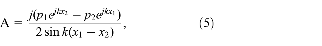
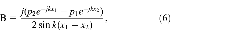
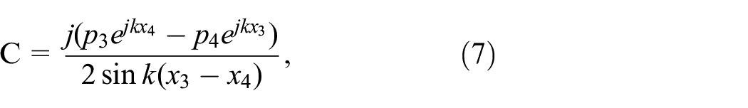

To simplify the calculation of transmission loss, the two microphones are placed at equal intervals. In this case, the transmission loss coefficient can be expressed as C/A, and the transmission loss is calculated as

where s =
The specimen to be measured in this study was fabricated based on the material of the actual bellows. The thickness of the specimen was 2.5 mm and the diameter was 30 mm, which was installed in the impedance tube, as shown in Figure 2. The impedance measurement equipment for the transmission loss measurement was composed as shown in Figure 3. White noise was emitted into the tube through the loudspeaker, and the noise was measured before it was transmitted to the specimen through two microphones. In addition, the noise passing through the specimen from the opposite side was measured through two microphones. The inner diameter of the impedance tube was 30 mm. White noise was generated using a spectrum analyzer (B&K 3550) and amplified through a power amplifier (B&K 2706).

Bellows silicone material.

Impedance tube of a two-microphone system.
Based on the analysis of the transmission loss for the specimen of the bellows (as shown in Figure 4), the transmission loss drops sharply in the resonance region of approximately 35 Hz in the low-frequency region. Furthermore, in the region above 100 Hz, it is increased by following the mass law of transmission loss; it was confirmed that the transmission loss is approximately 13–17 dB up to 1000 Hz. The specimen had a considerably lower transmission loss value compared to the other materials used in railway vehicles such as extruded aluminum.

Transmission loss of bellows silicone of 2.5 mm thickness.
Bellows are configured in a tube shape (as shown in Figure 5), and they are composed of various mechanical devices to connect to the vehicle. If this shape is considered for the analysis, it would require a considerable amount of time, and it would be difficult to perform an accurate analysis. Therefore, an analysis model (Figure 6) based on the cross section of tube-shaped bellows was adopted in this study. The bellows had a shape in which eight semi-sphered corrugations comprised both the outer and inner sides. The end parts of each corrugation were fixed by a connecting pin; moreover, the analysis was performed using the physical properties of silicone rubber to reflect the dynamic properties of actual bellows. Meanwhile, Young’s modulus, density, and Poisson values were equal to 170e9 Pa, 2329

Bellows in railway system.

Analysis model of existing bellows.
The natural frequency and natural mode were examined through the eigenvalue analysis of the analysis model. Based on the low-frequency region, the natural frequency was derived (Table 1). The derived results confirm that a number of natural frequencies exist from 54.2 Hz. The results of sequentially deriving the calculated natural frequencies from the low-frequency region confirmed that 20 natural frequencies exist up to 694.4 Hz. In particular, because the low-frequency region is sensitive to the vibration mode, a review of the related mode was performed, as shown in Figure 7. At 54 Hz, the outer corrugation part vibrates outward; furthermore, the inner corrugation part vibrates inward at 56 Hz. In particular, because the analysis has a shape wherein the outer and inner corrugations are separated from each other, the two eigenmodes exist at a frequency close to 55 Hz. Furthermore, in the 78 Hz region, the vibration was generated in the form of a number of corrugations shaking in the lateral direction.
Natural frequencies of existing bellows.


Various modes of existing bellows: (a) first mode: 54 Hz, (b) second mode: 56 Hz, and (c) third mode: 78 Hz.
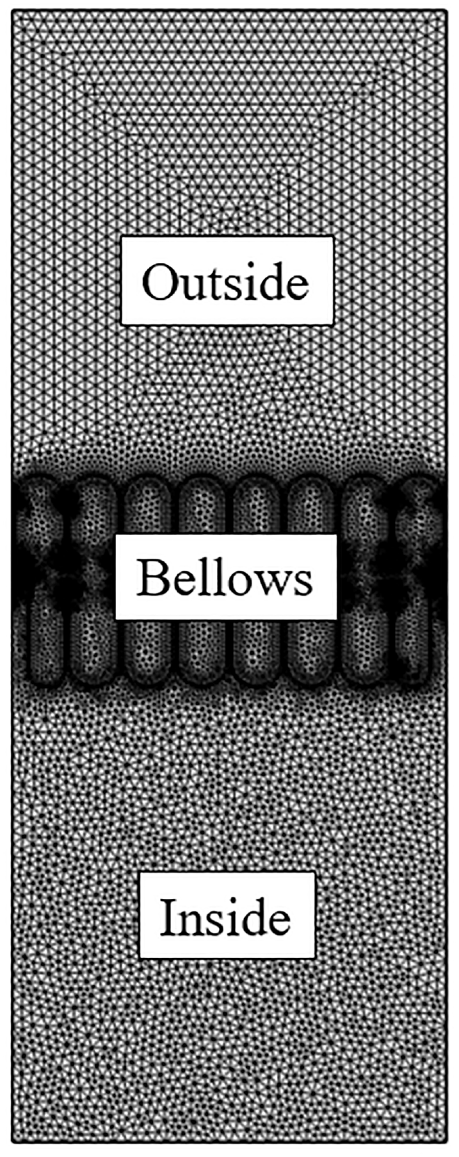
The acoustic-structure coupling analysis was performed on the external acoustic incident model based on the simple model to analyze the effect on transmission loss when an external sound is incident. First, as shown in Figure 8, a model for the air layer was added in the space, and the noise transmitted through the inside of the bellows was analyzed in an environment in which a plane wave of 1 Pa was horizontally incident from the outside. The number of meshes in the analysis model was 88569, and it had a dense shape because of the complex shape around the bellows.
Analysis model of structure-noise interaction of existing bellows.
The transmission loss incident on the bellows was analyzed (Figure 9) focusing on the low-frequency region. Based on the analysis results in the 31.5 Hz region (1/3 octave band), it can be seen that the noise incident from the outside of the bellows passes through the inside of the bellows, and it is transmitted to the interior area of the railway. Furthermore, the noise was reduced at each step. When the noise of 31.5 Hz is generated from outside and is incident, it can be seen that the vibration of the bellows shows the shape of the outer corrugations vibrating inward. Furthermore, it can be confirmed that the noise generated from the outside of the bellows is transmitted through the inside of the bellows, as seen in the 31.5 Hz area, even in the 63 Hz area. At this time, the vibration shows the shape of the inner corrugations vibrating inward; the most stressed part was the inner corrugations at both ends.

Structure-noise interaction of existing bellows at low frequencies range: (a) sound propagation at 31.5 Hz (dB, 1/3 octave band), (b) stress contours at 31.5 Hz (Pa, 1/3 octave band), (c) sound propagation at 63 Hz (dB, 1/3 octave band), and (d) stress contours at 63 Hz (Pa, 1/3 octave band).
Performance analysis of thickness improvement model
A review was conducted to improve the noise transmission performance of the bellows by changing the structure without filling the inside with a sound-absorbing material. To improve the transmission loss, it is effective to increase the thickness of the bellows; therefore, based on the basic theory of transmission loss, the effect of thickness in silicone rubber on the increase in transmission loss was examined. The bellows were composed of a shape with a number of wrinkles; however, the assumption of a silicone rubber plate was considered to simplify the analysis. In the case of a single partition, the transmission loss was calculated as follows. Furthermore, it was assumed that the partitions were in the air layer of the same medium and were flat, nonporous, and flexible. The sound power transmission coefficient (
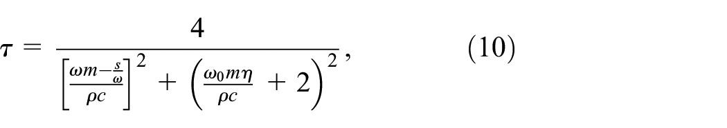
where m denotes the mass per unit area of the bellows;
Transmission loss (TL) can be obtained as

The surface density of the silicone rubber was 3.33 kg/

In this equation, quantitative relation between the thickness and transmission loss for a bellows can described by the following relations.

where t denotes the thickness of the bellows. Therefore, the transmission loss can be obtained as

Thus, as the thickness increases, the TL increases as well. Therefore, from the viewpoint of transmission loss, it means that the thickness of the bellows should be increased. However, increased thickness of the bellows may increase its manufacturing cost and may interfere with its movement. Therefore, the suitable thickness of the bellows should be considered based on various aspects.
Based on this relationship, when the thickness of silicone rubber is 2.5, 3.0, 3.5, and 4.0 mm, the transmission loss can be calculated as shown in Figure 10. It is not easy to measure or analyze the spring constant of the bellows because the comparison is performed by focusing on the region after the resonance frequency; therefore, it can be seen that the transmission loss increases as the thickness increases. When the thickness increases to 4.0 mm, there is a 4.1 dB increase compared to that for the 2.5 mm thickness. Further, when the thickness was increased to 3.5 and 3.0 mm, the noise increase was 2.9 and 1.6 dB, respectively

Transmission loss of single layer with various thickness of bellows.
The bellows are in the form of a tube, and therefore, they can be viewed as a two-layer structure rather than a single-layer structure. Accordingly, an analysis of the transmission loss was performed based on the two-layer structure. In the case of a two-layer structure, the theoretical equation for the transmission loss is as follows:
At first,

Furthermore,


where

At this time, the solution is
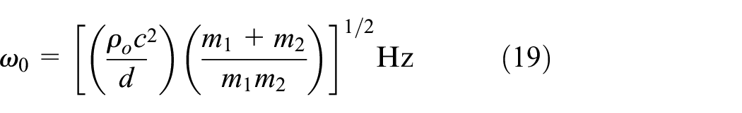
This is called the “mass–air–mass resonance frequency,” and the frequency tends to decrease as the distance between the two panels increases. Based on the above equation, the transmission loss in the silicone rubber for the double structure is as shown in Figure 11 when considering thicknesses of 2.5, 3.0, 3.5, and 4.0 mm. In this case, the equation is affected by the “mass–air–mass resonance frequency,” in addition to the resonance frequency. The panel with the highest transmission loss is 4.0 mm, which increases to 8.2 dB in the region above the “mass–air–mass resonance frequency” compared to the existing 2.5 mm. In addition, 3.5 and 3.0 mm thick panels were identified as 5.8 and 3.2 dB, respectively. However, when the thickness increased to 4.0, 3.5, and 3.0 mm in the region below the resonance frequency, the noise decreased to 4.2, 2.9, and 1.6 dB, respectively.

Transmission loss of double layers with various thickness of bellows.
The improvement in the noise performance of the bellows targeted in this study is more than 3.0 dB over the entire frequency range. To this end, as the thickness of the bellows increases, the manufacturing cost increases, and the resistance to a curved run caused by contraction and expansion may increase. Therefore, the verification was performed by setting the actual thickness of the bellows to 3.5 mm through the transmission loss analysis of the simple model previously performed. However, if the thickness is increased to 3.5 mm, the weight of the bellows can be increased. Therefore, a model in which the number of corrugations was reduced to seven from eight was designed as shown in Figure 12.

Analysis model of bellows with 3.5 mm thickness.
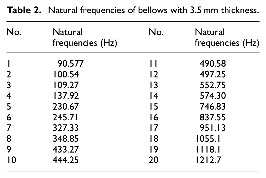
The natural frequencies and eigenmodes for the proposed model were analyzed. First, the natural frequency was derived (as listed in Table 2) from the lowest frequency region. Then, from the derived results, it was confirmed that a number of natural frequencies exist from 90.1 Hz. Based on the result of sequentially deriving the calculated natural frequencies from the low-frequency region, it was confirmed that 20 natural frequencies exist up to 1212.7 Hz. Through these results, it could be confirmed that the number of natural frequencies in the low-frequency region of the proposed model were reduced compared to those of the existing model.
Natural frequencies of bellows with 3.5 mm thickness.
In addition, because the noise performance in the low-frequency region is sensitive to the vibration mode, a review of the related mode was performed, as shown in Figure 13. First, at 90 Hz – first natural vibration mode – the outer corrugation part vibrates outward. In addition, in the second natural frequency mode, the inner corrugation part vibrates inward at 100 Hz. It was confirmed that the interval between the first and second natural frequencies was a little longer compared to the existing bellows model. In addition, in the region of 109 Hz, which is the third natural frequency, it was confirmed that vibration was generated in the form of a number of wrinkles shaking in the lateral direction.

Various modes of bellows with 3.5 mm thickness: (a) first mode: 90 Hz, (b) second mode: 100 Hz, and (c) third mode: 109 Hz.
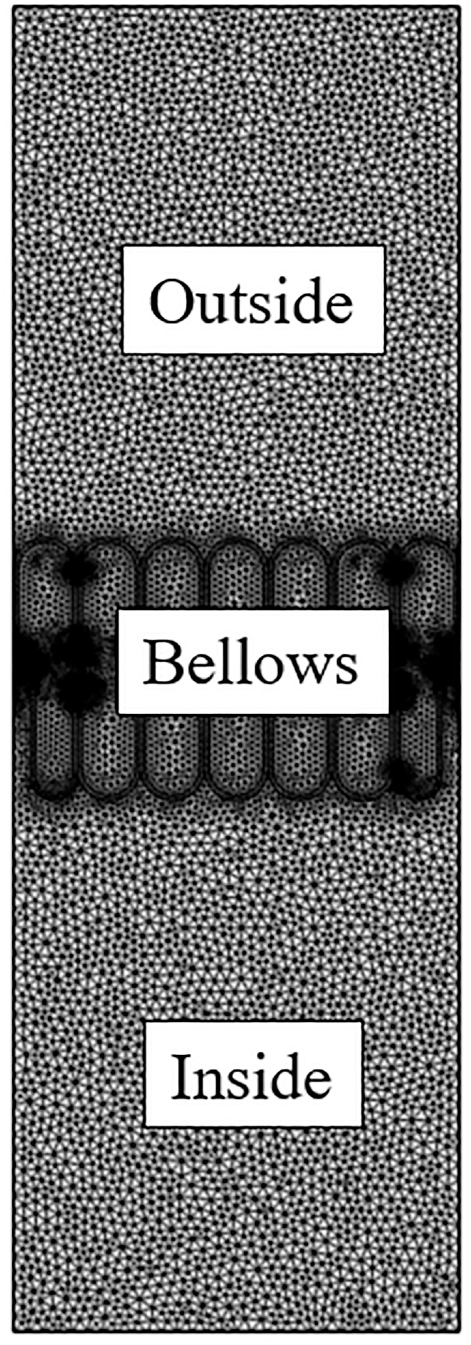
Next, acoustic-structure coupling analysis was performed on the external acoustic incident model based on a simple model to analyze the effect on the transmission loss when an external sound is incident on the bellows. First, as shown in Figure 14, a model for the air layer was added in the space, and the noise transmitted through the inside of the bellows was analyzed in an environment where 1 Pa of plane waves are horizontally incident from the outside. At this time, the number of meshes in the analysis model was 70804, and it is composed of a dense shape caused by the complex shape around the bellows.
Analysis model of structure-noise interaction of bellows with 3.5 mm thickness.
The transmission loss incident on the bellows was analyzed as shown in Figure 15 in the low-frequency region. The analysis results in the 31.5 Hz region (1/3 Octave band) indicate that the noise incident from the outside of the bellows passes through the inside of the cavity and is transmitted to the interior area of the train. In addition, it can be seen that the noise was reduced step-by-step. When the noise of 31.5 Hz is generated from outside and is incident, the vibration of the bellows shows the shape of the outer corrugation vibrating inward. Next, noise generated from the outside of the bellows is transmitted through the inside of the bellows, as seen in the 31.5 Hz area and even in the 63 Hz area. The vibration at this time shows that outer corrugations vibrated inward.
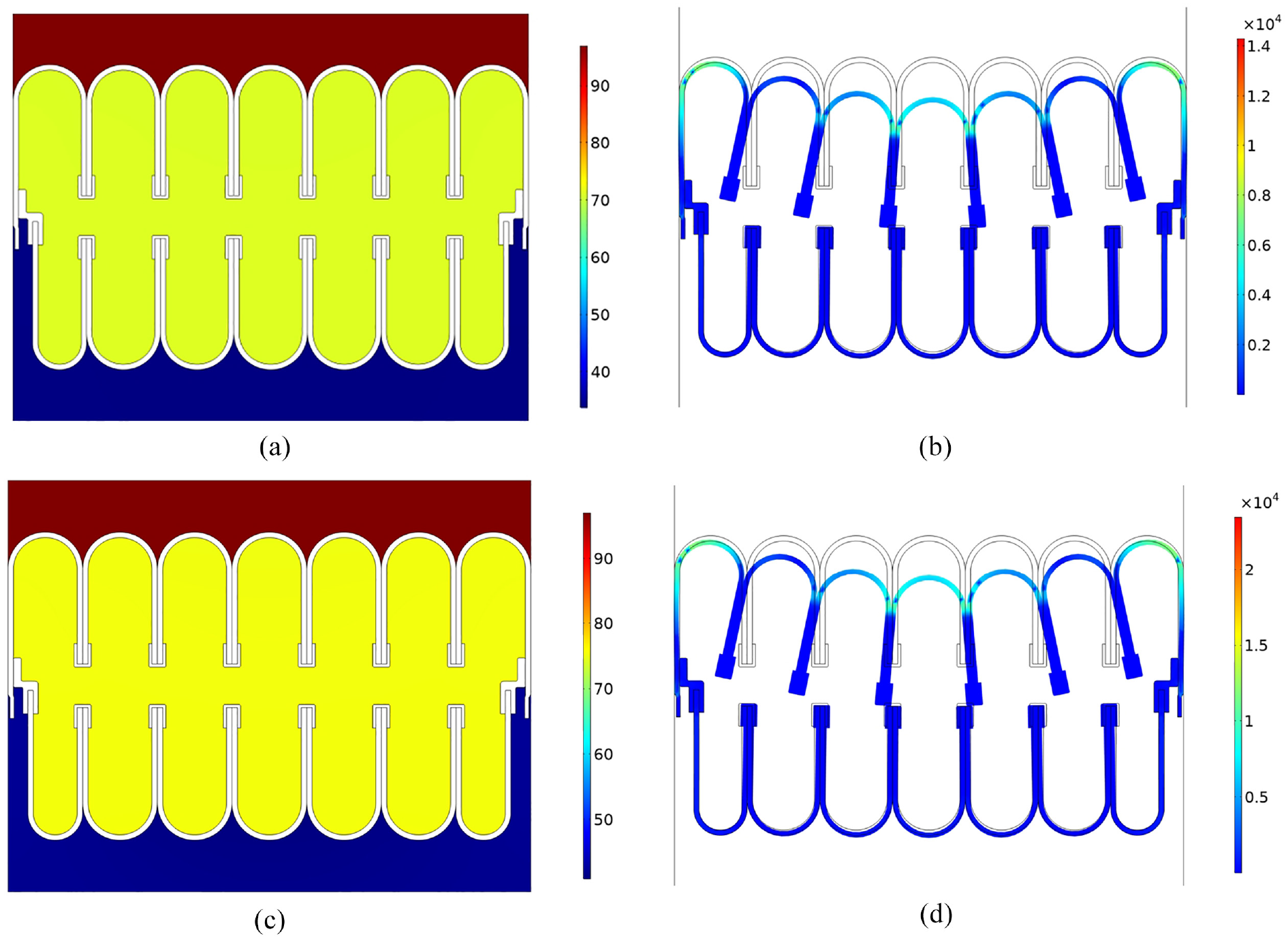
Structure-noise interaction of bellows with 3.5 mm thickness at low frequencies: (a) sound propagation at 31.5 Hz, (b) stress contours at 31.5 Hz (Pa, 1/3 octave band), (c) sound propagation at 63 Hz (dB, 1/3 octave band), and (d) stress contours at 63 Hz (Pa, 1/3 octave band).
Transmission loss was calculated as shown in Figure 16 based on the incident sound pressure based on the transmitted sound pressure of the bellows. From the measured results, the transmission loss increased in the low-frequency region when the thickness was increased to 3.5 mm. Sound propagation was found in the low-frequency regions of 31.5 and 63 Hz, and thus, the transmission loss improved as the vibration mode decreased.

Comparison analysis of transmission loss of bellows with 2.5 and 3.5 mm thickness.
Performance verification test
The noise reduction performance of the improved model was validated by comparing the existing bellows. To compare and examine the noise reduction performance of the improved model, a comparative test was performed with the existing bellows. The noise was measured based on the widely used measurement and analysis criterion 18 for the noise reduction performance of bellows.
In this measurement, the transmission loss of the bellows can be obtained as

Where
The reverberation chamber method was employed, in which the sound absorption rate and transmission loss were measured considering the reverberation time when the acoustic energy density becomes the same diffused sound field according to the space in the reverberation chamber. Furthermore, the test area of the bellows was calculated based on the horizontal incident area. The acoustic attenuation index of the bellows was calculated based on the difference between the average sound pressures in the sound source room and the sound receiving room, the area of the sample, and the sound absorption capacity of the sound receiving room.
As shown in Figure 17, a bellows was installed between the two reverberation chamber spaces. In one space, two MicroVee speakers (Velodyne) were placed as the sound source. In addition, five noise sensors of B and K were installed at a height of 1.5 m in each room to measure the generated noise. To measure noise reduction index of the specimen, the sound source room must first be energized with a sound from the speaker. Then, a sound level meter in the source receiving room measures the reverberation time for the decay of sound level. The reverberation time is the time the sound pressure level takes to decrease by 60 dB, after a sound source is abruptly switched off. In railway vehicles, the bellows have a central area passage to facilitate movement between cabins. Therefore, a sound insulation wall, with a height, width, and depth of 2500, 1700, and 95.5 mm, respectively, was implemented (Figure 18) to ensure that the sound did not propagate through the passage of the bellows. The sound insulation wall was composed of a medium-density fiberboard, concrete plaster, and rock wool. The sound insulation wall applied in this study was primarily made of 2400 mm concrete.

Sound source room for reverberation test.

Evaluating the noise reduction performance of bellows.
The differences in the analyzed transmission loss between the improved and existing bellows were analyzed, as shown in Figure 19. The noise reduction performance was measured based on a widely used measurement and analysis criterion 18 in which, the noise reduction index was between 100 and 5000 Hz. It can be seen that the transmission loss of the improved bellows was increased compared to the existing bellows. Compared to the 30 dB transmission loss of the existing bellows, the transmission loss of the improved bellows was 33 dB. In addition, because the bellows have a large number of corrugations and a complex structure, it was confirmed that a number of valleys exist based on the actual measurement results. In the case of both the improved model and existing models, the “mass–air–mass resonance frequency” was determined to be approximately 400 Hz. This is because both models have the same spacing. In addition, it was confirmed that there was a difference in transmission loss in the low-frequency region because of the difference in the spring constant caused by the thickness change.
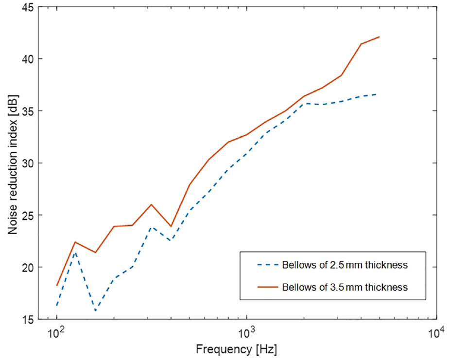
Noise reduction performance of existing and thickness reinforced bellows.
Furthermore, the result of comparing the frequency domain was analyzed as shown in Figure 20. From the analysis results, it was confirmed that the noise performance was the highest at 5.6 dB at 160 Hz. When the natural frequency analysis was performed above, it was confirmed that if the thickness was increased, the natural frequency increased because of an increase in the spring stiffness, and thus, the transmission loss in the low-frequency region was improved. Furthermore, it was confirmed that the transmission loss of the enhanced model was improved above 4000 Hz.

Difference in noise reduction between existing and thickness reinforced bellows.
Conclusion
The bellows of a railway vehicle are an area vulnerable to noise caused by low transmission loss among the components of the vehicle. Therefore, this study investigated an approach to improve the transmission loss of bellows by changing the thickness. From the analysis of the natural vibration model of the simple model, it was found that in the low-frequency region of the bellows, a number of vibrations occurred in the low-frequency region because of the vibration of the outer and inner parts. Therefore, to improve the transmission loss of the bellows, an analysis was performed based on the transmission loss theory by increasing the thickness from 2.6 to 3.0, 3.5, and 4.0 mm. The results of the analysis confirmed that the noise performance improved to 3.66 dB when the thickness was improved to 3.5 mm in the double-layer structure. In addition, the noise due to transmission significantly decreased in the low-frequency region after acoustic-structure coupling analysis was performed based on the simple model. A verification test for actual performance verification was performed. For performance verification comparison, a noise comparison test was performed for the existing and improved bellows. The results confirmed that when the thickness was increased to 3.5 mm, the existing noise reduction index improved by 3 dB from 30 to 33 dB. In comparison with the frequency domain, the highest noise performance was improved with an improvement of 5.6 dB at 160 Hz. The bellows developed in this study are meaningful in that the weight was reduced by lowering the number of wrinkles even though it improved the thickness and increased the transmission loss.
Footnotes
Handling Editor: Chenhui Liang
Declaration of conflicting interests
The author declared no potential conflicts of interest with respect to the research, authorship, and/or publication of this article.
Funding
The author disclosed receipt of the following financial support for the research, authorship, and/or publication of this article: This research was supported by a grant from Railroad Technology Research Program funded by the Ministry of Land, Infrastructure and Transport of Korean government and a grant from R&D Program of the Korea Railroad Research Institute, Republic of Korea.