
Abstract
Robot kinematic calibration used to be carried out with the partial pose measurements (position only) of dimension 3 in industry, while full pose measurements (orientation and position) of dimension 6 sometimes could be considered to improve the calibration performance. This paper investigates the effects of measurement dimensions on robot calibration accuracy. It compares the resulting robot accuracies in both partial pose and full pose cases after calibrating three structural types of robot manipulators such as a serial manipulator (Hyundai HA-06 robot), a single closed-chain manipulator (Hyundai HX-165 robot), and a multiple closed-chain manipulator (Hyundai HP-160 robot). These comparative studies show when the full-pose based calibration need to be considered and how much it contributes the improvement of robot accuracy to the different structural type of robot manipulators.
Keywords
Introduction
Recently, robotic manipulators have become more common in advanced applications (such as robot-based machining, laser welding, laser cutting, multiple robot cooperation, etc.). However, the robotic manipulator is highly repeatability but low accuracy. In order to enhance the precision of the robots, they should be undergone a calibration process before using.
The identification of kinematic errors in robot calibration normally requires experimental measurements of the robot end-effector, which consists of three orientation elements and three positional elements. In previous research,1–4 the authors claimed that only acquired robot end-effector positions are adequate in identifying the kinematic parameter errors. In order to determine the position of the robot end-effector tip, some studies used arrays of locating holes on the plate surface fixtures5,6 or on block fixtures. 7 The dowel pins are inserted into the holes to make three-dimensional coordinate points. In the work of Alici and Shirinzadeh, 3 the end-effector position is measured by a three-dimensional coordinate measuring device (e.g. Laser Tracker). In order to obtain a coordinate of the robot end-effector tip, Lightcap et al. 4 used a Coordinate Measuring Machine (CMM) while Khalil et al. 2 utilized two theodolites and a cylindrical target. Although the position measurements are used for robot calibration, other researches8–13 insisted that both position and orientation measurements of the robot end-effector should be acquired in order to utilize the maximum amount of information to accurately identify the robot kinematic parameters. An optical device for measuring the accurate full poses was designed and used to calibrate a SCARA robot. 11 In the works of Everett 8 and Driels et al., 10 the special tools which were attached to the robot’s last link had an arrangement of intermediate measuring points for deriving the robot end-effector full pose. Park et al. 12 utilized a structured laser module (fixed on the robot’s last link) and a camera to obtain the full pose measurements. Most recently, To and Webb 13 and Peng et al. 14 used TMAC (Tracker-Machine tool sensor) and a three-dimensional laser tracker to acquire the full pose of the robot end-effector. Zhang et al. 15 applied ultrasound to demonstrate partial pose measurements. Another approaching method is using line structured light by Xie et al. 16 In this work, the authors use the line structured light measurement system mounted on the tip of the robot to acquire full pose measurement. Thought, there have been no specific studies about how much this supplementary orientation information of the end-effector improves the robot positional accuracy. Therefore, it could be meaningful to carry out the calibration performance comparison in terms of the robot position accuracy with two cases of the pose set: (1) with full pose measurements (six dimensions), and (2) partial pose measurements (three dimensions). In order to get the insight for the effect of the more constraints to single pose of the manipulator, this comparison analysis is extended the various structural type of industrial manipulators such as a serial robot (Hyundai HA-06), a single closed-chain robot (Hyundai HX-165), and a multiple closed-chain manipulator (Hyundai HP-160). For the comparison analysis, the full pose and partial pose measurements are done with a number of M and 2M robot configurations, respectively. The method for collecting the full pose measurements is adopted from our previous work. 17 For validation of robot accuracy, a set of N arbitrary robot configurations are selected after calibration.
The rest of the paper is organized as follows. Section 2 describes the modeling of the three structural types of manipulators and the corresponding parameter identification equations of them. Section 3 shows the calibration simulation and results of the three types of manipulators with two cases of full pose and partial pose measurements, and also discusses the effect of the supplementary orientation information on the accuracy of the three types of manipulators. Section 4 presents conclusions.
Kinematic modeling of robots
This research considers the manipulators having different levels of structural complexity such as a serial robot, a single closed-chain robot, and a multiple closed-chain robot. Their kinematic models are developed in the following subsequent sections.
HA-06 robot
A serial robot (Hyundai HA-06) that has six degrees of freedom (DOF) is shown in Figure 1. In order to develop its kinematic model, we followed the method presented in John. 18 Coordinate frames are fixed on the robot links based on Denavit-Hartenberg (D-H) convention 19 and the corresponding D-H parameters are shown in Table 1. The transformation matrix from the robot base frame {0} to the robot last frame {E} can be computed by:

where

A schematic of a serial Hyundai HA-06 robot.
D-H parameters of HA-06 robot (length: (m);angle (°); X: not identifiable).

HX-165 robot
The HX-165 robot which is shown in Figure 2 has a single principle open chain and one closed-loop mechanism inside. The frames are fixed at the links of the open chain, which is connected by joints

where the matrix

A schematic of a Hyundai HX-165 robot.
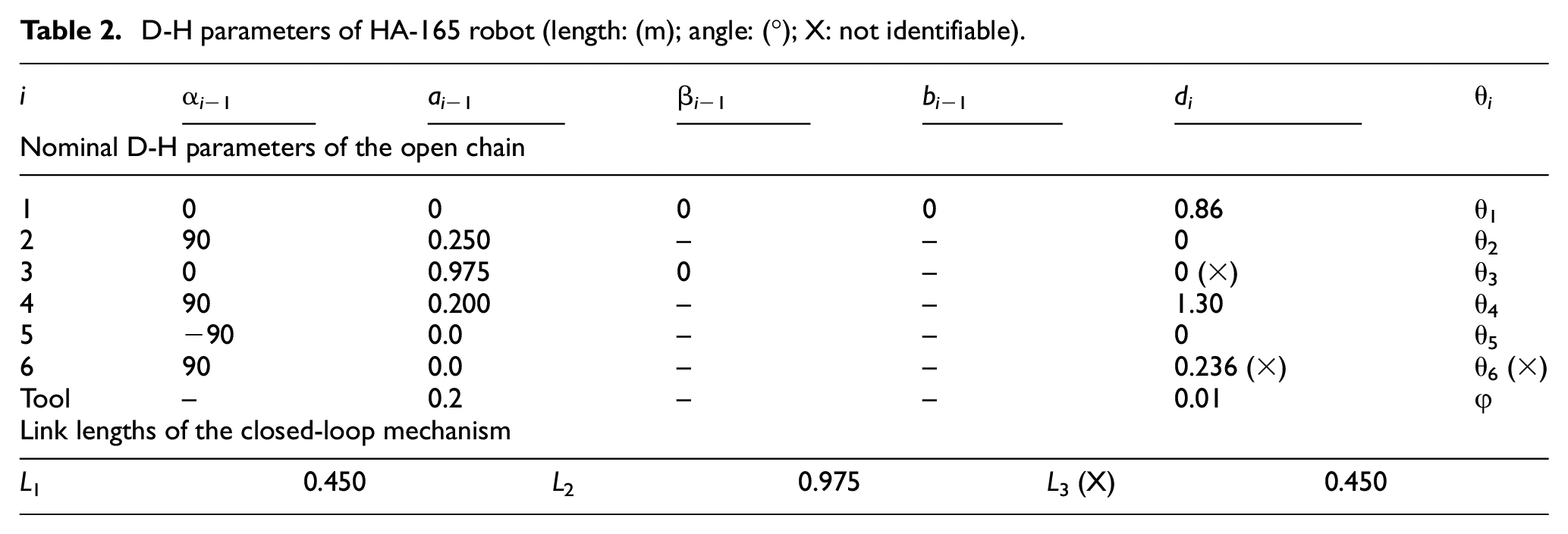
D-H parameters of HA-165 robot (length: (m); angle: (°); X: not identifiable).
HX-165 robot
The transformation matrix from the robot base frame {0} to the robot end-effector frame {E} is computed by:

where the matrices

A schematic of a Hyundai HP-160 robot.
The mathematical formulation for identifying the kinematic parameters of a robot is required in calibration process. 5 For a general serial robot which has n DOF, the differential transformation, which describes the relationships between the parameter errors of the open chain and the end-effector pose errors, is expressed as follows:

where
Since the structure of the HA-06 robot has an only single serial chain, the equations of robot parameter identification are formulated similarly to equation (4). For the single closed-chain robot HX-165, a global system of identification equations is formulated by incorporating the closure velocity constraints of the closed loops into the differential equations of the open chain via the passive joint. The velocity constraint equations of the five-bar closed chain PQRS can be written in the form of a function of the identifiable parameters:

The derivative of

The differential equations of the open kinematic chain of the HX-165 robot are described by expanding (4) as follows:

By substituting (6) into (7) via the passive joint

where the columns of
For the multiple closed chain robot (HP-160), a system of the global identification equations is formulated similarly to a single closed chain robot (HX-165), that is by incorporating the closure velocity constraints of the closed chain mechanisms into the differential equations of the open chain (4) via the passive joints
Simulation study
In this section, the comparison study is carried out with two cases of measurement data as the partial poses and full poses for three different manipulators via computer simulation. The simulation procedure for robot kinematic calibration consists of the following steps. M robot configurations in its workspace are specified by generating M sets of joint position readings. The kinematic parameter errors, which include the joint offsets and link geometric errors, are added to the nominal robot parameters in order to obtain an assumed physical robot. In practice, the result of the measurement process is not the real measured value due to the measured quantity or environmental condition change. Therefore, in the simulation, the normally distributed random noise values are added to the robot joint position readings and the robot end-effector position to simulate the measurement noise.
For each robot configuration, a vector of the end-effector positions X is obtained by solving the forward kinematics of the assumed physical robot when giving the set of joint position readings (the readings are corrupted by normally distributed random angle noises). The vector of measured position Xm is obtained by adding vector X to the measurement position noise (normal distribution). The robot joint random position noise values have the standard deviations of 0.0070 for joints 1, 2, 3, and 0.0040 for joints 4, 5, 6. The standard deviation values of the measurement noise along the x, y, z axes are 0.01 mm. In order to collect the robot end-effector orientation, a full pose measurement method in our previous work 17 is resorted.
In order to identify the unknown kinematic parameters, the calibration procedure uses the partial pose measurements with a number of M1 = 40 robot configurations and the full pose measurements with only M2 = 20 robot configurations. It is worth noting that
Since the end-effector positions are the functions of random quantities (joint angle corrupted by random noise), the end-effector positions are also random quantities. So, the simulation should be repeated until a statistically significant sample is obtained as explained in Zak et al. 21 The repeated number of the simulations is set as R = 20.
The criteria to determine the robot accuracy is to get the average of the repeated simulations shown in (9) and (10). Specifically, the mean position accuracy of the robot in the jth simulation run is computed for M2 configurations by:

where the index j refers to the jth simulation run (j = 1,…,R), “m” stands for “measured,”“c” for “computed,”
The mean position accuracy of the robot end-effector for R = 20 simulation runs is computed by:

where
The maximum errors
The robot position accuracy of the measurement data used in calibration is normally higher than its accuracy of the other arbitrary measurement points. Therefore, the robot accuracy should be computed for a set of arbitrary robot configurations. Here, an arbitrary data set is selected as V = 20. For the clarity of the future discussion, they are called as robot accuracy with data using in calibration and robot accuracy for validation, respectively.
Because the measurement noise is random, the validation is also repeated for R = 20 simulation runs. Formulas (9) and (10) are also used as validation criteria. The results of the calibration and validation processes for the three manipulators HA-06, HX-165, and HP-160 are presented in the subsequent sections.
For the HA-06 robot, the robot means position accuracy with the data using in each simulation run (i.e.

Mean position accuracy
Position accuracy of HA-06 robot (calibration).

The robot position accuracy is validated for a set of arbitrary measurement poses. The mean position accuracy for the simulation run

Mean position accuracy
Position accuracy of HA-06 robot (validation).

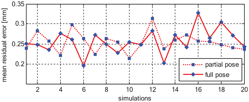
For the single closed-chain robot (HX-165), the robot means position accuracy with used data of each simulation run (i.e.

Mean position accuracy
Position accuracy of HX-165 robot (calibration).

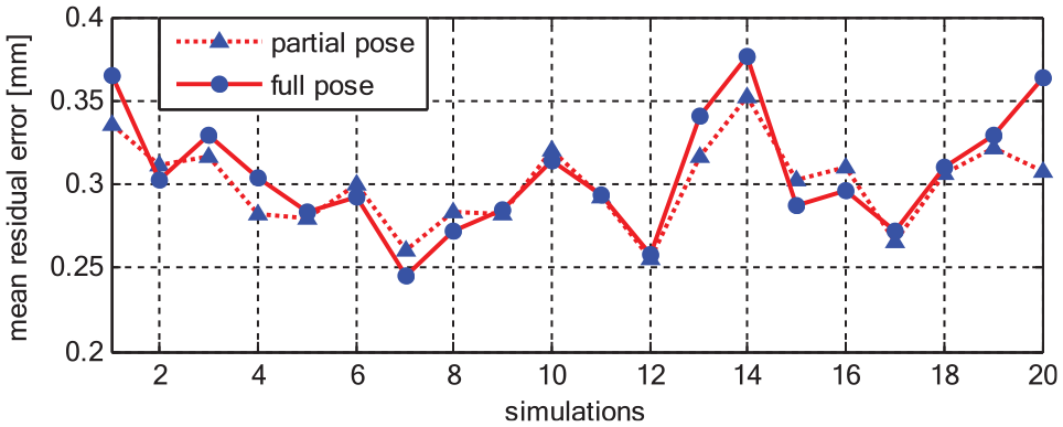
For the single closed-chain robot (HX-165), the robot means of position accuracy with the data using of each simulation run (i.e.
Robot position accuracy is validated at a set of arbitrary measurement poses. The mean position accuracy of the simulation runs
Mean position accuracy
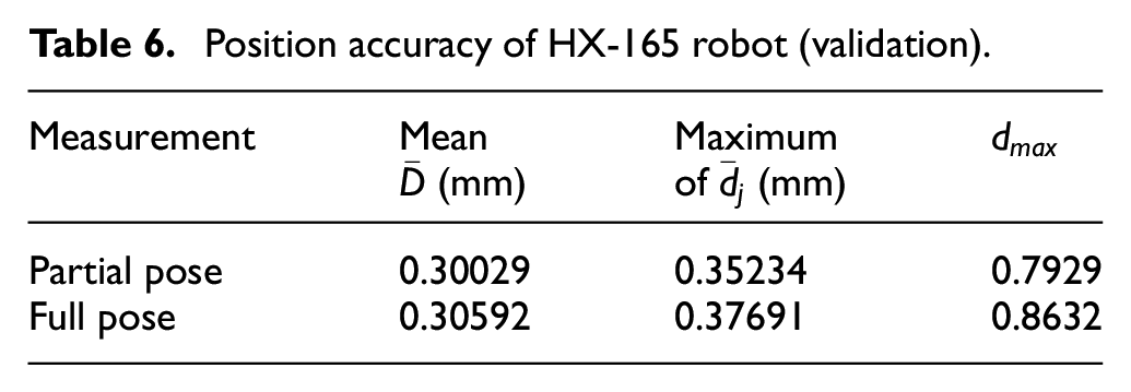
Position accuracy of HX-165 robot (validation).
For the HP-160 robot which has three closed-chain inside, the mean position accuracy with used data of each simulation run (i.e.
Mean position accuracy
Position accuracy of HP-160 robot (calibration).

Robot position accuracy is validated at a set of arbitrary measurement poses. The mean position accuracy of the simulation runs

Mean position accuracy
Position accuracy of HP-160 robot (validation).

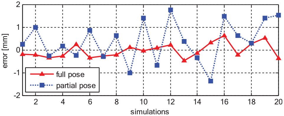
So far, from the calibration results of HA-06 and HX-165 robots, we can remark that the robot accuracy obtained by using the full pose is almost the same as the robot accuracy obtained by using the partial pose. However, for the studied HP-160 robot (having many closed chain mechanisms), the values of the identified closed chain parameters (link lengths of the closed-loop mechanism –Table 9) have a big difference from the assumed values. We examine the identified values of the robot parameters and then the deviation between a robot identified parameter value and its assumed value is computed. For example, ΔL2-1 = L2-1 assumed −L2-1 identified. If these deviations approach to zero values, the identified robot model is close to the physical robot kinematics, therefore the robot position accuracy is guaranteed. We examined the parameters (most inaccurate) of the closed chain mechanisms as follows: ΔL2-1 = L2-1 assumed − L2-1 identified. ΔL2-2 = L2-2 assumed − L2-2 identified. ΔL3-1 = L3-1 assumed − L3-1 identified.
D-H parameters of HP-160 robot (length: (m); angle: (°); X: not identifiable).

These deviation values are shown in the Figures 10 to 12. It is easy to see that with full pose measurement the deviations are close to zero. In the other words, for robots having multiple closed chains, the calibration using the full pose measurement results in more accurate robot parameters than the one using the partial pose measurements.

Parameter deviation ΔL2-1 of the closed chain mechanism (HP-160 robot).

Parameter deviation ΔL2-2 of the closed chain mechanism (HP-160 robot).
Parameter deviation ΔL3-1 of the closed chain mechanism (HP-160 robot).
Discussion
From this simulation studies, the supplementary orientation information does not seem to make a distinct contribution to improve robot accuracy for all of the three different types of robot manipulators, so long as the number of the constraint equations is the same for the calibration. Strictly speaking, the results for the multiple closed chain robot of HP-160 shows that the robot accuracy from full pose calibration show somewhat better than the robot accuracy from the partial pose calibration. The reason why it is will be explained as follows. The fluctuation of two parameters has never happen in other types of manipulators. Full pose constraint could help to refrain those parameters from being fluctuated during the calibration process.
Conclusions
This study compared the calibration performance of three typical robot types in terms of the robot position accuracy for two cases: calibration using full pose measurements and calibration using partial pose measurements that has not been carried out in the current literature. The structures of the robots examined have different levels of complication, from a simple serial link chain to a complicated structure with many closed-loop mechanisms. Three typical representative robots are the Hyundai HA-06, HX-165, and HP-160 robots.
The effects of orientation measurement of robot accuracy after calibration are studied. The comparative results show that the effect of orientation data on the identification accuracy of a serial robot and robot with a single closed chain is equivalent to the effect of position measurement data. However, with the robot has a complicated structure (e.g. HP-160 robot with three closed mechanisms), the full pose (orientation and position) measurement data is required for accurate identification of the robot parameters.
It is concluded that in order to calibrate the robot having multiple closed chains, full pose measurement data is necessary to guarantee the accurate identification of robot parameters. For a robot having simple structures like HA-06 or HX-165, the partial pose or the full pose data could be used equivalently in the calibration process. Future work concerns deeper analysis to applied different methods in identifying the parameters of robot using full pose measurements and calibration using partial pose measurements.
Footnotes
Handling Editor: James Baldwin
Declaration of conflicting interests
The author(s) declared no potential conflicts of interest with respect to the research, authorship, and/or publication of this article.
Funding
The author(s) disclosed receipt of the following financial support for the research, authorship, and/or publication of this article: This research was supported by Research Fund of University of Ulsan, Ulsan, Korea.