
Abstract
This paper proposes the virtual reconfiguration method (VRM) to construct the unified framework for closed-form solutions of a special class of serial manipulators. Central to the research is the inverse kinematics problem (KP) of 6- and 7-DOF serial manipulators, which contain either the Pieper's geometry or the Duffy's geometry. Given the desired end-effector pose of the manipulator, a virtual single chain (SLC) is developed by connecting the base and the end-effector with a hypothetical link. The equivalent single open chain (SOC) with different configurations can be obtained by cutting open the virtual SLC at one link between adjacent joints. Kinematic equivalence between the original manipulator and the new SOC is proven. Closed-form solutions of the original manipulator can be determined by solving the KP of the equivalent SOC. The VRM is further developed on the basis of the relationship between the manipulator and its equivalent SOC. In this paper, the KPs of 6-DOF manipulators with the spherical wrist and manipulators with the three-axis parallel shoulder joint are analysed. Principles and applications of the VRM are proposed. Finally, the validity and efficiency of the VRM are demonstrated by kinematics simulations of four different manipulators. Unlike traditional approaches, the VRM simplifies the computation of KPs and establishes a unified framework for closed-form solutions of the special class of 6- and 7-DOF serial manipulators, irrespective of the allocation of either the Pieper's geometry or the Duffy's geometry.
Keywords
1. Introduction
Serial manipulators are robots in a sequence of links and joints that begins at the base and ends with an end-effector. They are widely used in industry, humanoid robots and space exploration. The inverse kinematics problem (KP) of serial manipulators is the most important aspect of robot analysis and motion planning. It concerns determination of joint variables corresponding to the relative pose between two members of the manipulator. In this paper, the KP of a special class of 6- and 7-DOF serial manipulators, which contain either the 3-DOF spherical joint (Pieper's geometry) or the three-axis parallel geometry (Duffy's geometry), is proposed. In order to obtain inverse kinematic solutions of manipulators,
many methods have been developed based on different representations of position and orientation and their derivatives with respect to time [1, 2]. In general, the IKP of the special classes of manipulators can be solved with universal methods and particular methods, respectively.
Numerical methods are based on the computation of nonlinear kinematic equations in the position domain. Approximate inverse kinematic solutions can be determined using numerical methods such as interval methods, continuation methods and iterative algorithms [3, 4], etc. Numerical methods are independent of robot morphology and are applicable to robots with any kinematic structure. Nevertheless, a trade-off exists between the computational complexity and the solutions' precision. Also, it is impossible to find all kinematic solutions corresponding to the specified end-effector pose. Besides, the IKP of manipulators can be solved on the basis of inverse instantaneous kinematics. Typical methods are the simple Jacobian-based method and other extended methods including closed algorithms, Jacobian transpose methods, and so on [2, 5]. The velocity-based methods are applicable to manipulators irrespective of their geometry. However, these methods have intrinsic inaccuracy because of the linear approximation of the Jacobian matrix, especially in the near region of singularity. These methods are also dependent on the initial conditions and do not consider the feasible region of solutions. In addition, artificial neural networks and numerous intelligent algorithms are also capable of computing inverse kinematic solutions [6, 7]. These methods have excellent capabilities of parallel computing, and do not need an explicit kinematic model. But they are usually required to learn online or off-line from kinematic samples. The precision of the results is inadequate for some sensitive tasks.
Particular methods for approaching the IKP of manipulators are based on direct mapping from the Cartesian space to the joint space. Inverse kinematic solutions can be expressed symbolically using algebraic or geometric methods [1, 8]. Closed-form solutions are more efficient than numerical algorithms and readily identify all possible exact solutions leading to the desired terminal position and orientation. This indicates the desirability of closed-form solutions above other universal approaches. However, closed-form solutions depend on the robot morphology, and they only exist for a few types of robots, including six-degree-of-freedom (DOF) serial manipulators with three adjacent revolute joint axes intersecting at a common point (Pieper's geometry or spherical joint), or manipulators with three consecutive revolute joint axes in parallel (Duffy's geometry) [9, 10]. Manipulators with the spherical wrist joint or the three-axis parallel shoulder joint are desirable because the IKP can be solved easily by kinematics decoupling. Nevertheless, for general manipulators including humanoid arms with the spherical shoulder joint or space robots with the Duffy's geometry locating in the middle part, it is difficult to derive with closed-form solutions by solving high-degree polynomial equations. The IKP of these manipulators simply resorts to numerical algorithms or intelligent approaches.
A few studies have been carried out for closed-form solutions for these types of manipulators. In [11], closed-form solutions of the 7-DOF humanoid arm are expressed by fixing one redundant joint. In [6], the approximate closed-form solutions of the inverse kinematic model are obtained using evolutionary algorithms and genetic programming technology. However, the establishment of the approximating models is time consuming, and the results are inadequate for fine manipulations. In [12], an analytical method is used for the 7-DOF humanoid arm with a spherical shoulder joint, and closed-form solutions are derived using the virtual joint method. However, the seventh joint angle needs to be given before other solutions are obtained, and the method is invalid for 6-DOF serial manipulators. The reverse-decoupling method is presented for humanoid robots with the spherical joint, and the IKP is approached using algebraic algorithm and matrix transformation [1]. However, there is no in-depth study on the principle of the reverse-decoupling method. In [13], the reverse-coordinates method is used for closed-form solutions of 6-DOF manipulators with the SRRR configuration. But this method is only applicable to manipulators with spherical shoulder joint. There is no unified framework for the IKP of manipulators satisfying the Pieper's condition and manipulators satisfying the Duffy's condition.
This research is motivated by closed-form solutions of a class of serial manipulators with the special geometry. This paper is organized as follows. The IKPs of two kinds of typical manipulators are analysed in Section 2. Principles and applications of the VRM are proposed in Section 3. The validity and efficiency of the VRM are demonstrated by case studies of typical manipulators in Section 4. Conclusions are presented in Section 5.
2. IKPs of Typical Manipulators
2.1 Manipulators with the Spherical Wrist
Pieper's geometry is equivalent to the spherical joint (S, which can achieve rotations in three different directions. Manipulators are usually designed with a spherical wrist to achieve better performances of the end-effector. The spherical wrist is widely used in industrial applications.
Suppose that the general 6-DOF manipulator contains the revolute joint (R) and the prismatic joint (P). The manipulator with the RPRS arrangement is shown in Figure 1.

General RPRS manipulator with the spherical wrist
Let j A i be the homogeneous transformation matrix describing the pose of Frame Oixyz with respect to Frame Ojxyz. Point W is the intersection of the last three joint axes. The kinematic equation of the general 6-DOF serial manipulator with the spherical wrist can be expressed as

where
In brief, for the general 6-DOF serial manipulator with the spherical wrist, the position of the wrist point W depends only on the first three joint variables. The spherical wrist is used to adjust the terminal orientation. Given the desired end-effector pose, closed-form solutions can be obtained in two steps: the first three joint variables are derived from the position-based equation f0P6(v1, v2, v3), and then the spherical wrist angles can be solved based on the orientation-based equation f0R6(θ, d).
2.2 Manipulators with the Duffy shoulder joint
Duffy's geometran achlies to the three-axis parallel planar robot, which can achieve two-dimensional motions. In order to simplify the inverse kinematics, Duffy's geometry is designed as the shoulder joint of manipulators. Similarly, the general 6-DOF manipulator with the 4RPR configuration is shown in Figure 2.

General 4RPR manipulator with a Duffy shoulder joint
According to the forward kinematics, the end-effector pose 0A6 can be expressed as
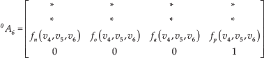
where the elements denoted by * are omitted, which vary with all joint variables. fn(v4, v5, v6), f o (v4, v5, v6), fa(v4, v5, v6) and fp (v4, v5, v6) are functions related to the last three joint variables.
Therefore, for the general 6-DOF serial manipulator with the Duffy shoulder joint, the position and the orientation of Frame m O6x yz along the z direction of Frame O0xyz depend only on the last three joints. Given the desired end-effector pose, closed-form solutions can be obtained in two steps: the last three joint variables are derived from the third row of 0A6, and then the shoulder joint angles can be computed from other rows of 0 A6.
3. Theory of the VRM
3. 1 Backgrounds
As mentioned above, for the general 6-DOF manipulator with the spherical wrist or the Duffy shoulder joint, closedform solutions can be directly obtained by decoupling certain elements of the end-effector pose. Furthermore, the general 7-DOF manipulator with these special geometries can be simplified as the 6-DOF robot by fixing one redundant joint, and the IKP can then be solved analytically [11]. Nevertheless, in order to meet special requirements of operations and environments, different types of serial manipulators are developed which satisfy the Pieper's or the Duffy's condition. However, these manipulators are not equipped with the spherical wrist or the Duffy shoulder joint. For instance, humanoid arms with the spherical shoulder joint and humanoid legs with the Duffy's geometry in the middle part can better emulate human functions [1]. Space manipulators are usually designed as symmetrical robots with the Duffy's geometry, so they can be folded for delivery to ISS [14–16]. Though closed-form solutions for these manipulators exist, it is difficult to derive the solutions directly since all elements of the position and orientation are coupled.
This paper presents a unified procedure for solving the IKP of a special class of the 6-DOF and the 7-DOF serial manipulators which contain either the Pieper's geometry or the Duffy's geometry.
3.2 Analysis of Kinematic Equivalence
Manipulators are kinematically equivalent if they have the same kinematic relationship between joints and links, inherently. Kinematic equivalence between the general serial manipulator and its reconfigured form is proven as follows.
1. Forward Kinematic Equivalence
In Figure 3(a), the general n-DOF serial manipulator with a closed is illustrated. Given the specified joint variables, the position and orientation of links are uniquely determined.

Kinematic chain of the general manipulator: (a) the closed-loop manipulator; (b) Robot-A; (c) Robot-B
Based on the closed-robot, an n-DOF reconfigured manipulator “Robot-A” with an open loop is developed by cutting open the kinematic chain at Link n, as shown in Figure 3(b). For a certain serial manipulator, the position and orientation of links are determined by joint variables. Since all joint variables remain unchanged, there are no joint motions during the reconfiguration process. Thus, given the specified joint variables, the position and orientation of the corresponding elements in the Cartesian space are identical between the two manipulators. The original closed-loop manipulator is forward-kinematically equivalent to its reconfigured form with a closed loop.
Another reconfigured manipulator, “Robot-B”, can also be obtained by cutting open the kinematic chain at Link i, as shown in Figure 3(c). Similarly, given the specified joint variables, the poses of corresponding elements in the Cartesian space are the same between these closed-loop manipulators and Robot-B. This implies that forward-kinematic equivalence exists between the two serial manipulators.
According to the above analysis, the two different reconfigured manipulators with the open loop are forward-kinematically equivalent because of the identical pose of corresponding elements in the Cartesian space corresponding to the certain joint variables. On the other hand, Robot-B can be developed by connecting two ends of Robot-A with a hypothetical link and cutting open the kinematic chain at Link i. Robot-B can be deemed one of the reconfigured manipulators of Robot-A. Consequently, it can be concluded that the general serial manipulator is forward-kinematically equivalent to its reconfigured manipulator with an open loop.
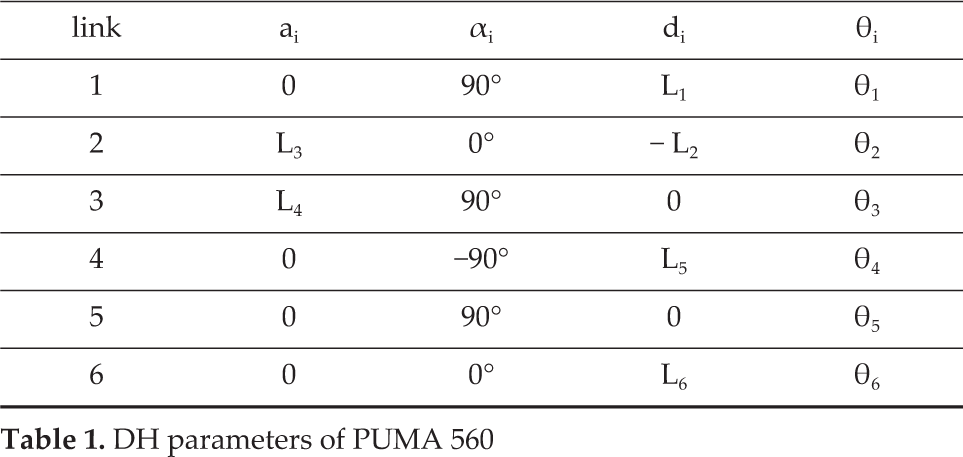
In order to validate the forward kinematic equivalence, the kinematics of PUMA 560 is established. DH coordinate frames of the robot are established in Fig 4(a), DH parameters are listed in Table 1. Based on this, the kinematic equation yields
DH parameters of PUMA 560
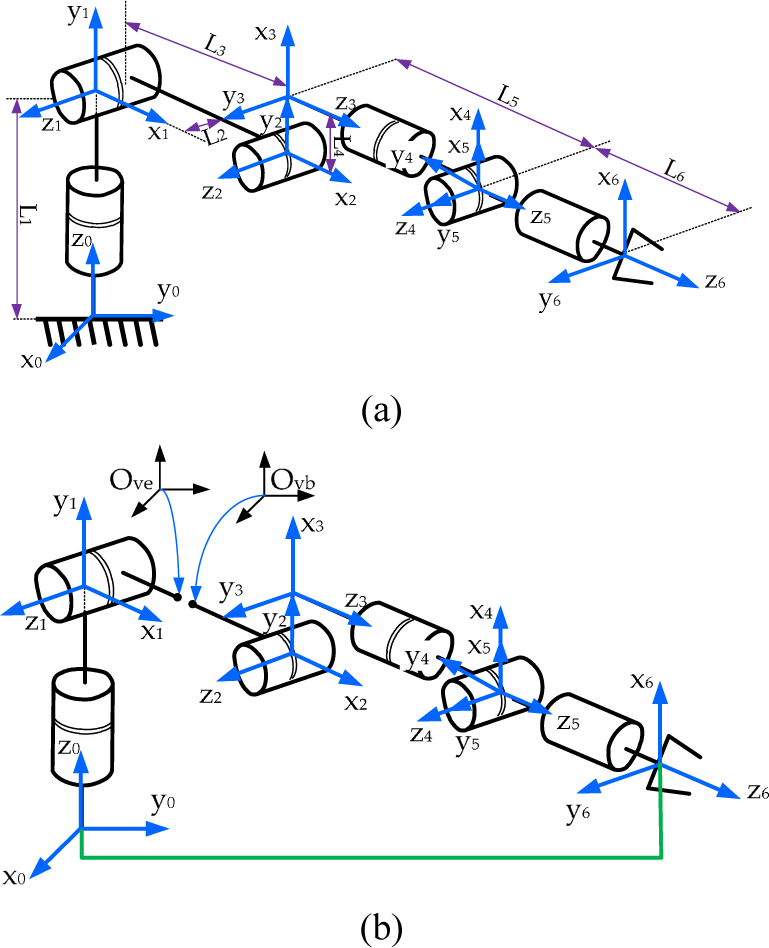
DH frames of robots: (a) PUMA 560; (b) the reconfigured robot

The reconfigured robot can be obtained by connecting two ends of the robot with a hypothetical link and cutting open the kinematic chain at Link 2. The virtual frames (Frame vb and Frame ve) are arbitrary and identical. DH coordinate frames are established as shown in Fig 4(b). The kinematic equation of the reconfigured robot is expressed as

Based on (2) and (3), it can be seen that PUMA 560 and the reconfigured robot have the same kinematic equation. This demonstrates that the reconfigured robot is forward-kinematically equivalent to PUMA 560.
2. Inverse Kinematic Equivalence
Inverse kinematic equivalence between the original manipulator and the open-reconfigured manipulator is proven using proof by contradiction.
Suppose that

or

If Case I is true, the relative pose of corresponding elements of the original manipulator is different from that of the reconfigured manipulator corresponding to the joint variables

Similarly, if Case II is true, the relative pose of corresponding elements of the reconfigured manipulator is different from that of the original manipulator corresponding to

Based on the above analysis, inverse-kinematic solutions
Therefore, it is proven that the original manipulator is kinematically equivalent to its reconfigured form.
The original manipulator and the reconfigured manipulators have identical kinematic singularity. The spherical joint at a singularity is illustrated in Figure 5(a). An arbitrary reconfigured form of the spherical joint is developed, as shown in Figure 5(b). It can be found that the two manipulators have identical characteristics at the singularity. Also, the equivalence of singularities can be validated by the kinematic equations from (2) and (3).

Kinematic singularity of the 3-DOF manipulator: (a) the spherical joint at singularity; (b) the reconfigured manipulator at singularity
3.3 Principles of the VRM
The serial manipulator with an open kinematic chain is termed the single open chain (SOC), and the manipulator with a closed chain is termed the single chain (SLC). As mentioned above, given the specified joint variables, the end-effector pose with respect to the base frame is confirmed, and a stationary constraint exists between the base and the end-effector. Assuming that one virtual connection is built between the base frame and the end-effector frame (EEF), the virtual SLC is developed to be kinematically equivalent to the SOC. At this point, a new equivalent SOC with different configurations can be obtained by cutting open the virtual SLC at one link between adjacent joints. Various equivalent SOCs can be gained from the same manipulator by selecting different breaking points. The equivalent SOC also varies directly with different poses of the end-effector. Hence, the equivalent SOC can be deemed the variable-geometry robot.
With respect to the specified end-effector pose, the equivalent SOC has the same inner relationship between joints as the original serial manipulator. Hence, by cutting open the connection before the Pieper's geometry, manipulators with one internal spherical joint can be transformed into the equivalent SOC with the spherical wrist. Likewise, manipulators with the Duffy shoulder joint can also be derived from robots which contain the three-axis parallel structure. The theory to change the configuration of manipulators through the equivalent SOC is termed the virtual reconfiguration method (VRM). Based on this, reconfigurations of the manipulator with the Pieper's geometry and the manipulator with the Duffy's geometry are performed respectively.
A 6-DOF kinematic chain with the spherical joint is shown in Figure 6. The base frame and the EEF are established, and then the SLC is developed by virtually connecting these two frames. In order to obtain a new SOC with the spherical wrist, Link 4 is broken into two parts: Link 4' and Link 4″.

Kinematic chain of the manipulator with the spherical joint: (a) the original SOC; (b) the equivalent reconfigured SOC
Link 4' connects with Joint 5, and Link 4” connects with Joint 4. The virtual base frame Ovbxyz is built arbitrarily at the breaking point on Link 4’, and the virtual EEF Ovexyz is fixed to the breaking point on Link 4”.
The pose of Frame Ovexyz with respect to Frame Ovbxyz can be expressed as

The relationship between Frame O4‘xyz and Frame O4″xyz can be derived from (4). Because Frame Ovbxyz coincides with Frame Ovexyz, 4’A4” is simplified as

According to (5), the new equivalent SOC is equipped with the spherical wrist. Since the homogenous transformation matrixes bA0 and 4‘A4″ depend only on the geometrical structure of manipulators, given the desired end-effector pose, closed-form solutions of the manipulator can be solved directly with traditional methods.
The 6-DOF kinematic chain with the three-axis parallel structure is shown in Figure 7. Similarly, the SLC is developed by virtually connecting the base frame and the EEF. In order to obtain the new equivalent SOC with the Duffy shoulder joint, Link 1 is broken into two parts: Link 1' and Link 1′′. Link 1' connects with Joint 2, and Link 1′′ connects with Joint 1. The virtual frame Ovbxyz is built at the breaking point on Link 1', and the virtual EEF Ovexyz is fixed to the breaking point on Link 1″. Frame Ovexyz coincides with Frame Ovbxyz.
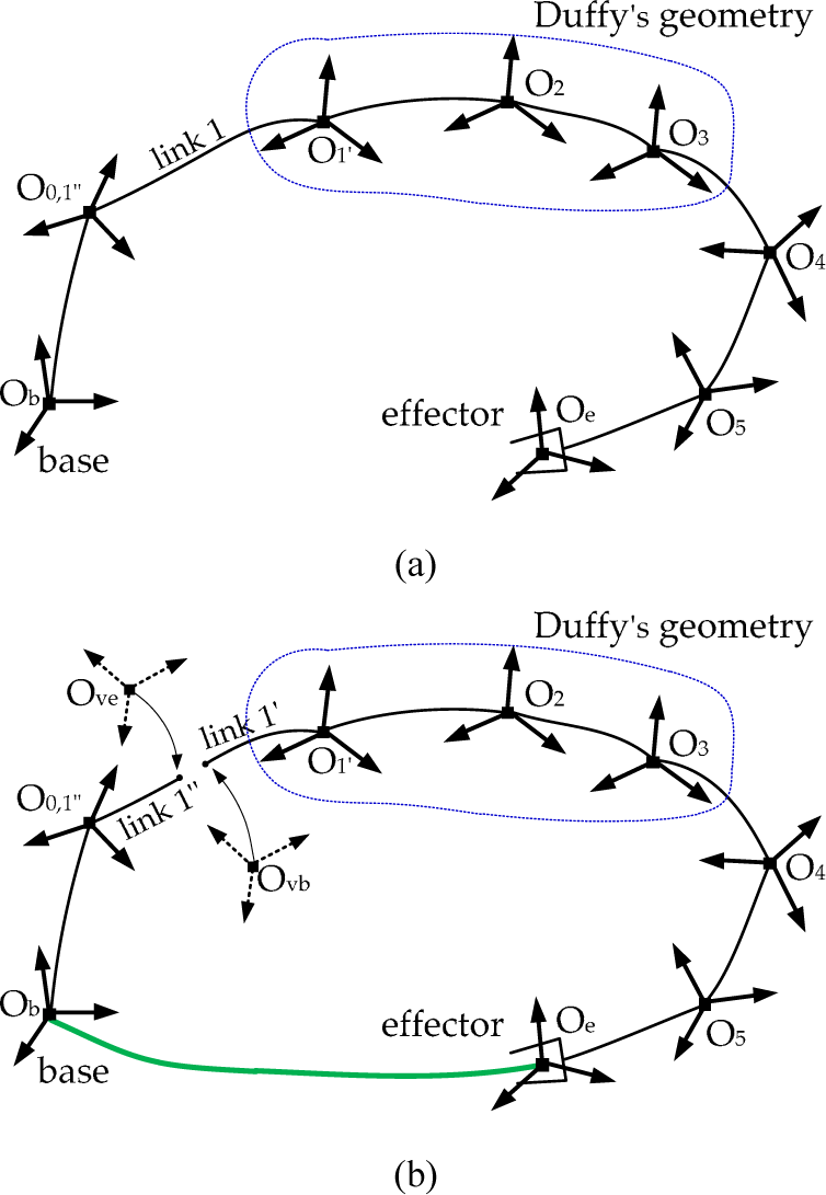
Kinematic chain of the manipulator with the Duffy's geometry: (a) the original SOC; (b) the equivalent reconfigured SOC
The pose of Frame Ovexyz with respect to Frame Ovbxyz can be obtained by composing the homogeneous transformation, and the relationship between Frame O1‘xyz and Frame O1″xyz can be simplified as

Therefore, the new equivalent SOC is equipped with the Duffy shoulder joint. Since the matrixes bA0 and 1‘A1″ depend only on the geometrical structure of manipulators, given the desired end-effector pose, closed-form solutions can be obtained using traditional methods.
3.4 VRM Algorithm
Corresponding to the end-effector pose, the VRM can be used to transform manipulators into robots with different configurations. It is worth sketching the procedure to compute closed-form solutions for serial manipulators satisfying the Pieper's condition and serial manipulators satisfying the Duffy's condition. In general, the algorithm is implemented in six steps, as follows.
3.5 Discussions
The VRM is developed based on the kinematic equivalence between the original manipulator and the equivalent reconfigured manipulator. The reconfigured manipulator is a subset of the reconfigurable robots because of the changeability of geometry. The comparisons between the equivalent reconfigured manipulator and the general reconfigurable robot are summarized as follows.
Another aspect to be considered for manipulators is the kinematic optimizations. Inverse kinematics involves one-to-many mapping from the Cartesian space to the joint space. For instance, given the specified terminal pose, there are at most eight solutions for the 6-DOF manipulator with either the Pieper's or the Duffy's geometry [20]. In order to determine the best of all feasible solutions, typical criteria are defined as follows.
Manipulability w1(v)

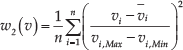
Distance from joint limits w2(v)
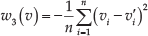
Distance from previous solutions w3(v)
Distance from an obstacle w4(v)

As mentioned above, the specified criteria are considered according to the requirement of the operations. The optimal joint displacements can be determined from all feasible solutions.
3.6 Applications
The topological structure describes a group of mechanisms which have the common characters between adjacent members. In this section, the topology structures of serial manipulators which contain either the Pieper's geometry or the Duffy's geometry are illustrated.
The topological structure of manipulators can be exactly expressed with three basic elements: the type of kinematics pair, connection relations between structural units, and the dimensional constraint type [21]. The prismatic joint and the revolute joint are the typical kinematics pairs. The basic dimensional constraint types are defined as follows.
SOC with two adjacent kinematics pair (R or P) axes intersecting at one common point is expressed as

SOC with two adjacent kinematics pair (R or P) axes being parallel to each other is expressed as

SOC with two adjacent kinematics pair (R or P) axes in the general configuration is expressed as

The topology structure of the Pieper's geometry and the Duffy's geometry can be represented as
Suppose that the 6 DOFs SLC with the Pieper's geometry is denoted as
Based on the topological structures of these two types of manipulators, many manipulators can be developed due to different link parameters and joint allocations [1, 14–16]. The VRM is applicable to any manipulator belonging to Type I and Type II manipulators. It simplifies computations of the IKP and constructs the unified framework for closed-form solutions for one special class of serial manipulators.
4. Case Studies
4.1 IKPs of humanoid arms
The 6-DOF serial manipulator is generally used for humanoid robots to be able to imitate human motions. The humanoid arm of Hubo KHR-4, which has the spherical shoulder joint, is illustrated in Figure 8.

The equivalent SOC and DH coordinate frames
Case 1:
The base frame and the EEF of the humanoid arm are established, and the virtual SLC is developed. Based on this, the equivalent SOC is obtained by cutting open the virtual SLC at Link 3. DH coordinate frames of the equivalent SOC are established, and DH parameters are as listed in Table 2.
DH parameters of the humanoid arm

The base frame coincides with Frame O0xyz and 3″A3‘ is a constant transformation matrix which can be derived from Table 2. Consequently, computations of the kinematic equation as in (5) yield

Since the spherical joint is the wrist of the equivalent SOC, the position of Frame O1xyz viewed from Frame O3xyz depends only on the joint variable as θ4,5,6. The equation about the wrist position can be derived from (7). Let [pX pY pZ]T or be the end-effector position with respect to the base frame. If 

The parameters g1, g3, f 1, f 3, ρ, A and B are computed in the Appendix.
Otherwise, the kinematic singularity occurs. In this case, sinθ4 = 0, and θ5 can be determined directly according to some roles.
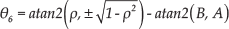
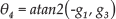
Supposing that R= b Re eR5 5R4 4R3‘ 3’R3″, substituting (8)–(10) into (7), solutions of the spherical joint can be derived. If sinθ2 ≠ 0, the joint angles are given by


Otherwise, the spherical joint is at a singularity. In this case, θ1 can be determined directly according to some roles. θ3 is given by

where

Finally, closed-form solutions of the humanoid arm are obtained. Given the desired end-effector pose, the corresonding joint angles can be determined directly.
Case 2:
With respect to Figure 9, another spherical joint exists which consists the third joint, fourth joint and fifth joint. In order to validate the universality of the VRM, another equivalent reconfigured manipulator is developed based on the humanoid arm. Differently from Case 1, the equivalent SOC is obtained by cutting open the virtual SLC at Link 5. DH coordinate frames of the equivalent SOC are established, and DH parameters are listed in Table 3.
DH parameters of the humanoid arm
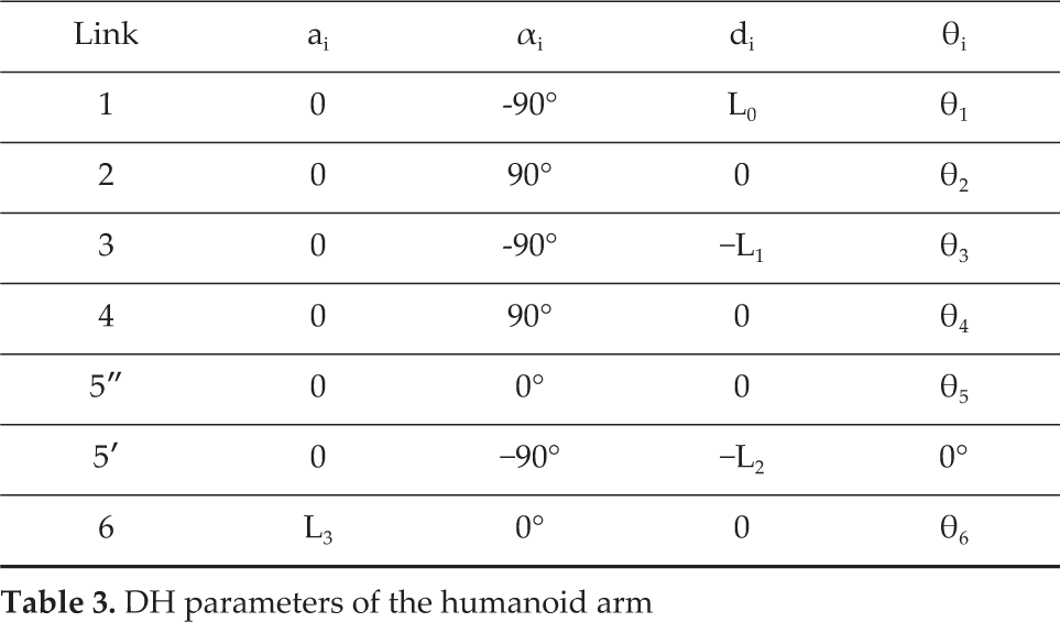

The equivalent SOC and DH coordinate frames
Similarly, 5″A5‘ is a constant transformation matrix which can be derived from Table 3. Computations of the kinematic equation as in (5) yield

Since the spherical joint is the wrist of the equivalent SOC, the position of Frame O4xyz viewed from Frame O5‘xyz depends only on the joint variable θ1,2,6. With reference to the above analysis, the equation of the wrist position can be derived from (15). θ1,2,6 can be derived using analytical methods. Finally, closed-form solutions of the new equivalent reconfigured manipulators are determined by kinematic decoupling. Due to the limitation of space, mathematical formulations of closed-form solutions are not expressed again.
In order to verify the validity of the VRM, kinematics simulations are performed. The joint range is from −180° to 180° without joint limits. The link parameters of the humanoid arm are obtained from its specifications as:
L0=214.5(mm), L1=179.14(mm), L2=181.57(mm), L3=80(mm). Let
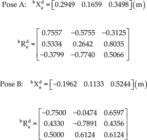
Closed-form solutions are completed based on the analysis in Case 1 and Case 2. Eight sets of solutions are obtained for Pose A, and four sets of solutions for Pose B, as illustrated in Table 4. Based on this, optimal kinematic solutions can be selected based on the typical criteria mentioned in Section 3.5.
Computed solutions of the humanoid arm (unit: degree)

According to Table 4, the computed pose corresponding to each solution can be derived. Errors between specified pose and computed pose are computed which are all less than 1e-14. The verification process is illustrated in Figure 10, which shows that closed-form solutions accurately correspond to either the general terminal pose or the special pose at kinematics singularities. Hence, the VRM is valid to solve the IKP of manipulators satisfying the Pieper's condition.

The validation process for kinematic solutions
4.2 IKPs of SFA
Duffy's geometry is the typical structure used in space robots, which can achieve a larger motion range and can be folded with minimal volume. Small Fine Arm (SFA) is one manipulator among the Japanese Experiment Modules [16]. The 6-DOF space robot with the three-axis parallel structure is shown in Figure 11.

The space robot and DH coordinate frames
Similarly, the equivalent SOC is obtained by cutting open the virtual SLC at Link 1. The DH coordinate frames of all links are established. DH parameters are listed in Table 5.
DH parameters of the 6-DOF robot

It is obvious that bA0 is the identity matrix and 1″A1‘ is a constant transformation matrix which can be derived from Table 5. The computation of kinematic equations is specified as

Since the Duffy's geometry is the shoulder joint of the equivalent SOC, the wrist pose in z direction of the base frame depends only on θ1,5,6. The first joint angle is expressed as

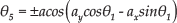

The parameters a and b are computed in the Appendix.
Otherwise, sinθ5=0, and θ6 can be determined directly according to some roles.
The space robot is now simplified as a planar robot including Joint 2, Joint 3 and Joint 4. Closed-form solutions of the 3-DOF planar robot are given by


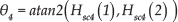
The parameters LSW, Hsc2 and Hsc4 are illustrated in the Appendix.
Finally, closed-form solutions of the 6-DOF space robot are obtained from (17)–(22).
In order to demonstrate the validity of the VRM, kinematics simulations are performed. The joint range is from −180° to 180° without joint limits. Link parameters of the robot are expressed as follows: L0=200 (mm), L1=435 (mm), L2=435(mm), L3=180(mm), L4=180(mm), L5=441(mm).
Similarly, two sets of the desired end-effector poses are examined. The first one (Pose A) is the general hand pose, and the second one (Pose B) is the pose at singularity.

According to (17)–(22), eight sets of solutions are obtained for Pose A, and six sets of solutions for Pose B, as illustrated in Table 6. Optimal kinematic solutions can be selected based on the typical criteria mentioned in Section 3.5. With reference to Figure 10, the errors between specified pose and computed pose are obtained, which are less than 1e-14. Closed-form solutions are accurate corresponding to either the general terminal pose or the special pose at kinematics singularities. It is verified that the VRM is valid for the IKP of manipulators satisfying the Duffy's condition.
Computed solutions of the SFA (unit: degree)

4.3 IKPs of 7-DOF manipulators
7DOF manipulators are redundant manipulators. There are infinite inverse kinematic solutions corresponding to one specified end-effector pose. The non-redundant manipulator can be developed by fixing one of the joints. In this section, the 7-DOF humanoid arm with the offset wrist and the space manipulator SSRMS is examined.
Figure 12 shows the equivalent reconfigured manipulator of the humanoid arm. By parameterizing the seventh joint of the humanoid arm, closed-form solutions can be derived using the VRM. The equivalent SOC is obtained by cutting open the virtual SLC at Link 3. The computation of kinematic equations is specified as

The equivalent SOC of the 7-DOF humanoid arm

Based on (23), parameterized solutions can be obtained. Let [pX pY pZ]T be the EEF position with respect to the base frame. If


The parameters g1, g3, f1, f3, ρ, A and C are computed in the Appendix.
Otherwise, the kinematic singularity occurs. In this case, sinθ4=0, and θ5 can be determined directly according to certain principle.
Supposed that R=bR e e R 66R5 5R44R3‘ 3’R3″, the solutions of the spherical joint can be derived. If sinθ2≠0, the joint angles are given by


Otherwise, the spherical joint is at the singularity. In this case, θ1 can be determined directly according to certain principle. θ3 is given by
where

Finally, closed-form solutions of the 7-DOF humanoid arm are obtained. Given the desired end-effector pose, the corresponding joint angles can be determined directly.
In order to demonstrate the efficiency of the VRM, closed-form solutions of the parameterized humanoid arm are carried out in Matlab 7.1 environment running on an Intel(R) Core(TM) 2 Duo CPU 1.83GHz PC. At the same time, the IKP is also solved by the well-known Newton-Raphson algorithm and the simple Jacobian-based method. The position error between the desired end-effector pose and the computed pose is defined as 0.001(m). Given 20 sets of arbitrary end-effector pose in the workspace, the efficiency of each method is illustrated in Figure 13. The comparisons demonstrate that the VRM is valid and efficient to solve the IKP of the manipulator analytically.

The efficiency of three different methods
Similarly, the equivalent SOC of SSRMS is developed by cutting open the virtual SLC at Link 2, as shown in Figure 14. The computation of kinematic equations is specified as

The equivalent SOC of the SSRMS

By parameterizing the first joint of SSRMS, closed-form solutions are derived using the VRM. The second joint angle is expressed as

If


The parameters ρ, A, B, D1 and D2 are computed in the Appendix.
Otherwise, sinθ6=0, and θ7 can be determined directly according to some roles.
The space robot is then simplified as a planar robot including Joint 3, Joint 4 and Joint 5. Closed-form solutions of the 3-DOF planar robot are given by


The parameters LSW, Hsc3 and Hsc5 are illustrated in the Appendix.
Finally, parameterized closed-form solutions of the 7-DOF space robot are obtained from (32)–(37).
In order to highlight the efficiency of the VRM, computations of the IKP of the parameterized manipulator are completed using different methods. Twenty sets of arbitrary end-effector poses in the workspace are given. Figure 15 shows the computation time using three different methods. It shows that the VRM is faster in determining kinematic solutions than the other two methods.
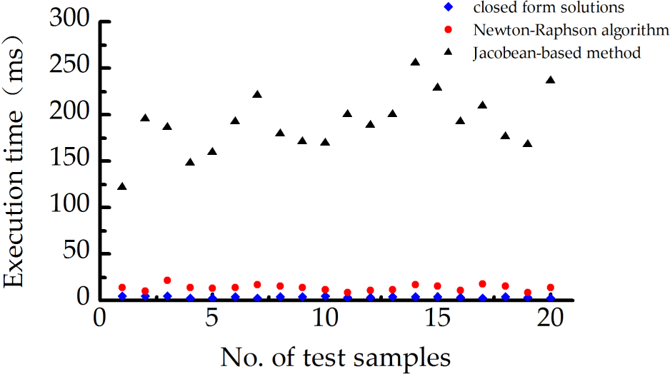
The efficiency of three different methods
In conclusion, the VRM is a valid and efficient approach to solve the IKP of manipulators analytically. It is applicable to serial manipulators containing either the Pieper′ or the Duffy's geometry.
5. Conclusions
In this paper, a unified framework has been proposed for closed-form solutions of a special class of 6- and 7-DOF serial manipulators containing the Pieper's geometry or the Duffy's geometry. Given a specified end-effector pose of the general manipulator, an equivalent reconfigured form can be developed. The reconfigured manipulator is kinematically equivalent to the original manipulator. The virtual reconfiguration method (VRM) is proposed on the basis of the kinematic equivalence between the two manipulators. Hence, for any serial manipulator satisfying either the Pieper's condition or the Duffy's condition, the equivalent SOC with the spherical wrist or the Duffy shoulder joint can be developed using the VRM. Closed-form solutions can also be obtained by solving the IKP of the equivalent SOC using traditional methods. The validity and efficiency of the VRM are verified by kinematic simulations of humanoid arms and space robots. Unlike traditional approaches, the VRM simplifies the computation of the IKP and establishes a unified framework for closed-form solutions of the special class of 6- and 7-DOF serial manipulators irrespective of the allocation of the Pieper's geometry or the Duffy's geometry.
Footnotes
6. Appendix
Parameters of the IKP for the 6-DOF humanoid arm are given by
Parameters of the IKP for SFA are given by
Parameters of the IKP for the 7-DOF humanoid arm are given by
Parameters of the IKP for the 7-DOF SSRMS are given by
7. Acknowledgements
This work is supported by the National 973 Programme under Grant No. 2011CB013306 and the National Natural Science Foundation of China under Grant No. 51175106.