
Abstract
When applied to some tasks, such as payload handling, assembling, repairing and so on, the two arms of a humanoid robot will form a closed kinematic chain. It makes the motion planning and control for dual-arm coordination very complex and difficult. In this paper, we present three types of resolved motion control methods for a humanoid robot during coordinated manipulation. They are, respectively, position-level, velocity-level and acceleration-level resolved motion control methods. The desired pose, velocity and acceleration of each end-effector are then resolved according to the desired motion of the payload and the constraints on the closed-chain system without consideration of the internal force. Corresponding to the three cases above, the joint variables of each arm are then calculated using the inverse kinematic equations, at position-level, velocity-level or acceleration-level. Finally, a dynamic modelling and simulation platform is established based on ADAMS and Matlab software. The proposed methods are verified by typical cases. The simulation results show that the proposed control strategy can realize the dual-arm coordinated operation and the internal force of the closed chain during the operation is controlled in a reasonable range at the same time.
Introduction
With the rapid development of space technology, the building and application of a space station is very important for the world. Compared with a single-arm space robot, a multi-arm robotic system has much more dexterity and flexibility and is capable of completing more complex tasks [1, 2]. The well-known space robot systems launched at the International Space Station, i.e., Dextre [3] and Robonaut 2 [4], have two arms. Funded by NASA (National Aeronautics and Space Administration), the University of Maryland has developed a dexterous multi-arm robotic servicing system — Ranger [5]. Moreover, DARPA (The Defense Advanced Research Projects Agency) is carrying out the Front-End Robotics Enabling Near-term Demonstration (FREND) project to investigate the feasibility of using three robotic arms to grapple an existing cooperative or non-cooperative satellite [6]. Recently, the DARPA Phoenix project [7] will develop three-arm space robots to cooperatively harvest and re-use valuable components from retired GEO satellites and create new spacecraft. China is also carrying out ambitious space exploration programmes, including a Chinese space station plan and Moon/Mars landing and sampling plans. Humanoid robots with high flexibility and mobility are under development to meet the complex space missions [8]. Coordinated motion planning is the key to its applications.
For the motion generation of a humanoid robot, a computational method using a simple pin-and-drag interface to generate whole-body motion is proposed in [9]. Neo et al. [10] developed a framework that integrates command by an operator with autonomous function in whole-body motion generation. Only the necessary points are selected by the operator. Yoshida et al. [11] proposed a whole-body motion generation method driven by the task. In order to achieve the goal task, the proposed method reshapes the support polygon when the task is beyond the ability of the robot. A whole-body reaching motion planning for collision avoidance is proposed in [12], which takes the time spent on the planning and the priority of the environment model into account. For a multi-arm space robot system, one or more arms can be used to counteract the reaction of the arms performing the on-orbit servicing mission, thereby stabilizing the base during the mission. Yoshida et al. [13] developed the Generalized Jacobian Matrix of a multiple-arm space robot and proposed a coordinated control method for the two arms: one traces the desired path, while the other maintains the satellite attitude. Furthermore, the control torques were minimized by redundancy resolution when three reaction wheels and a redundant arm were mounted [14]. All the joint variables of the two arms and the reaction wheels were combined in a differential kinematics equation and many more state variables were required to be solved for control. For example, the equation in [13] used for resolved acceleration control has 15 DOFs. The computational load is relatively large. Moreover, reaction wheels were used. Huang et al. used a balance arm to stabilize the base attitude in [15], where the joint velocities were determined according to the momentum conservation equations. The above methods [13–15] only considered the attitude stabilization of the base and complex dynamic singularities [16] arose during attempts to solve the inverse differential kinematic equation. Agrawal [17] and Xu [18] studied the coordinated motion control method to maintain the base attitude and centroid position simultaneously.
In the process of dual arms co-operation [18], such as load handling, demolition and installation process, there will be a closed kinematic chain. The closed kinematic chain is more complex than the open chain in dynamics, path planning and control when there will be contact force with the environment [19]. Hence, it has received significant attention recently. Jia et al. [20] proposed a dynamics-based adaptive control approach for a planar dual-arm space robot in the presence of closed-loop constraints and uncertain inertial parameters of the payload. Hu and Vukovich [21] have studied the force-position hybrid control of a closed kinematic chain of a multi-arm space robot system. Agrawal [22] presented an algorithm for motion planning of a planar free-floating closed-chain space robot, based on the inverse position kinematics of the mechanism. Papadopoulous has explored multi-arm space robot tracking and the dynamics and control of target capturing [23]. Moosavian and Papadopoulos have proposed a centroid vector method, direct path method [24] and multi-arm compliant control method [1]. The authors of [25] analysed the internal force during the multi-arm coordinated operation and proved the non-uniqueness of non-squeezing load distribution. In [26], a proper load distribution strategy for a heterogeneous cooperative manipulation setting was proposed to distribute the desired object wrench considering both constant and time-varying constraints. A centralized impedance control strategy and an active decentralized impedance control are provided to realize a compliant behaviour of the object and control the internal forces on the object in [27] respectively.
At present, most scholars have studied the operating force of the dual-arm coordinated operation. The strategies of load distribution and internal force analysis were proposed for dual-arm coordinated manipulation as in [25–27]. The resolution of dynamic equation was indispensable in this method, which takes much computational effort. However, we present the control strategies of dual-arm coordinated manipulation from the aspect of the kinematic closed-chain constraints without consideration of the internal force, which reduces the complexity and the difficulty of motion planning and control of a dual-arm robot.
In this paper, we study the resolved motion control of a humanoid robot for coordinated manipulations. Three types of control methods are presented at different levels: position-level, velocity-level and acceleration level. They are respectively called resolved position control, resolved rate control and resolved acceleration control. Moreover, a dynamic modelling and simulation platform is established based on ADAMS and Matlab software. The proposed methods are verified by typical cases. The simulation results show that the internal force during the dual-arm coordinated operation with resolved motion control is acceptable.
Modelling of the Dual-arm Robot with Closed Chain
Model of a humanoid robot
The configuration of a dual-arm humanoid robot is shown in Figure 1. It has four branches including two feet and two arms (the two arms are denoted as Arm-a and Arm-b, corresponding to the left arm and right arm respectively). Each branch has seven revolute joints, which are arranged in the structure–(Roll-Yaw-Pitch)-Pitch-(Pitch-Yaw-Roll). This structure is the so-called S-R-S layout. The first three joints intersect at one point, forming a sphere joint, known as the shoulder; the last three joint axes also intersect at one point to form a sphere joint, called the wrist; the fourth is the elbow joint. The D-H coordinate systems and the corresponding parameters are shown as Figure 2 and in Table I, respectively.
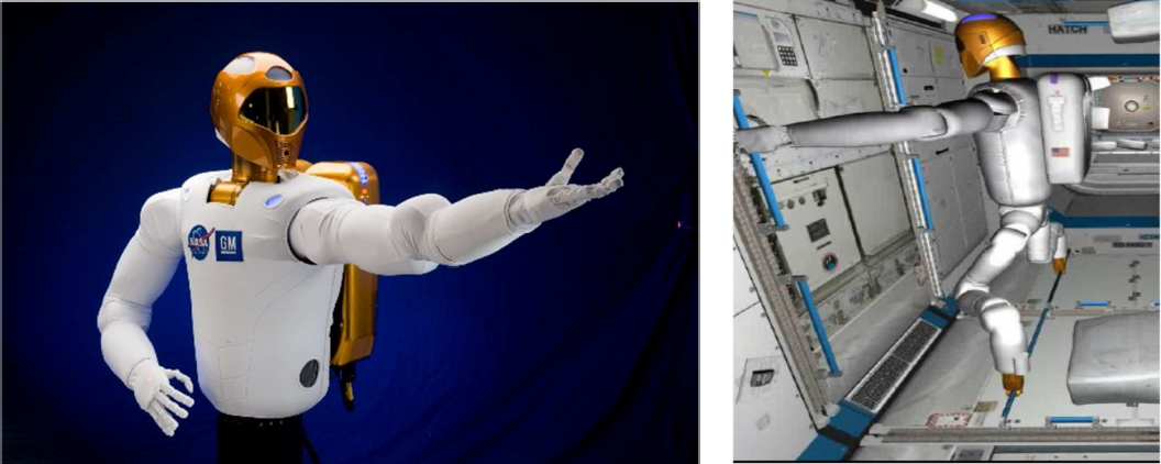
A humanoid robot used in the ISS (from NASA Web)
A frame is located on the main body of the humanoid robot and used as the reference frame for dual-arm coordination. It is denoted as {Ref} frame. In this paper, the values of the structural parameters are as follows: a3=−0.054m, a4=0.054m, a7=0.19m, d1=d3=d5=0.35m. The homogeneous transformation matrixes of the base frames of the two arms with respect to the reference frame are as follows:

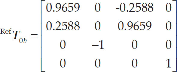
where,

The redundant manipulator and its D-H parameters
D-H Parameters

Each arm has the following kinematic relations:
Position-level kinematic equations
The forward kinematic equations of the two arms are written as:


where,
Velocity-level kinematic equations
The linear and angular velocities of the manipulator with respect to the base are as follows:


where,
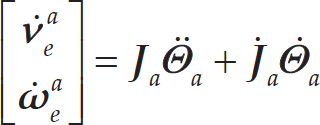
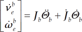
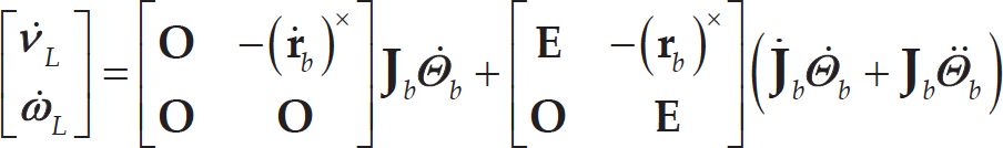
Acceleration-level kinematic equations
Differentiating the two sides of Eqs. (5) and (6) respectively, we get the following kinematic equations, i.e., acceleration-level kinematic equations:
Dynamic equations with environment interaction
When the two arms' end-effectors interact with the environment, the dynamic equations are written in the following forms:


where, M
k
(k = a, b) is the mass/inertia matrix; the first term in (10) represents the inertial forces due to acceleration of the joints; the second term (C
k
) represents the Coriolis and centrifugal forces; the third term (G
k
) is the gravity;
A general closed kinematic chain model formed by the two arms is shown in Figure 3. When the two arms grasp a common object, the position, velocity and acceleration of the two arms satisfy certain constraints.
Position-level kinematic equations
First of all, considering the position constraints of the dual arms, the position and orientation of the gripped load is denoted as {XLYLZL}. The other coordinate systems are defined as follows and shown in Figure 4:
{XBYBZB}: The body frame of the humanoid robot.
{X0aY0aZ0a}: The base frame of Arm-a, fixed to the body of the humanoid.
{XeaYeaZea}: The end-effector frame of Arm-a.
{X0bY0bZ0b}: The base frame of Arm-b, fixed to the body of the humanoid.
{XebYebZeb}: The end-effector frame of Arm-b.
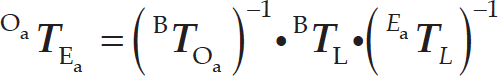
From the geometric relationship shown in Figure 4, the pose of the payload with respect to the body frame is according to the kinematic equations of Arm-a, i.e.:

Constraints on a dual-arm robot

On the other hand, the pose of the payload with respect to the body frame can be calculated according to the kinematic equations of Arm-b:

where,


When the desired pose

The position constraint equation needed to be satisfied between Arm-a and Arm-b is as follows:

i.e.,


The position constraints on a closed-chain system
When the dual arms form a closed chain and manipulate the objective load, the velocity relations are shown in Figure 5, where:
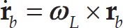
There exists the following relationship between Arm-a and the payload:
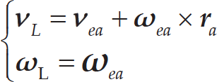
equation (19) can be written as follows:

Similarly, the relationship between Arm-b and the payload can be derived as:

According to (20) and (21), we get:

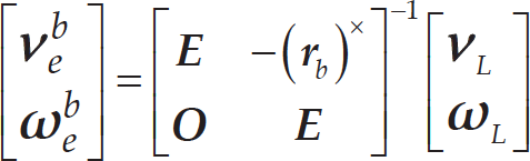
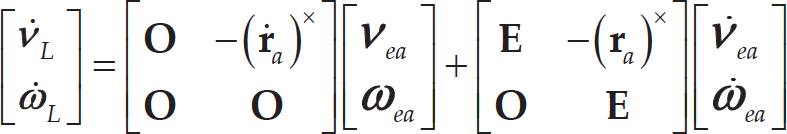
On the one hand, considering (5) and (20), we can get:

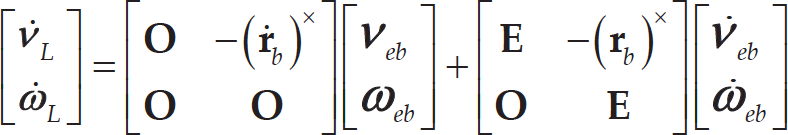
Otherwise, combining (6) with (21), we can have:

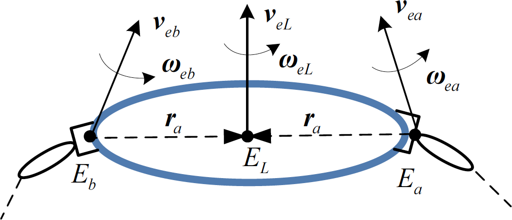
The velocity constraints of the robot forming a closed chain
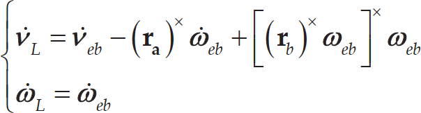
Differentiating both sides of (19) respectively, we can get the following kinematic equations, i.e., acceleration-level kinematic equations:

where,

Eq. (26) can be written as:

Similarly, there are the following equations for Arm-b:
Eqs. (29) and (30) can be written in the matrix forms:
Further, combining Eqs. (5), (6), (7) and (8), we can have:

The two arms forming a closed chain then have the following constraint:

Considering the kinematic constraint equations derived above, we propose the “coordinated resolution” strategy for decomposing the motion of the common object into the motion of dual arms. The concept of coordinated resolution means that the desired pose of each end-effector is calculated from the closed-chain constraint equations formed by the common object and dual arms simultaneously. The definition of coordinated resolved motion position control, coordinated resolved motion rate control and coordinated resolved motion acceleration control are given as follows, respectively:
Coordinated resolved motion position control
The key to the coordinated resolved motion position control lies in resolving the position constraint equation, as shown in Figure 6.
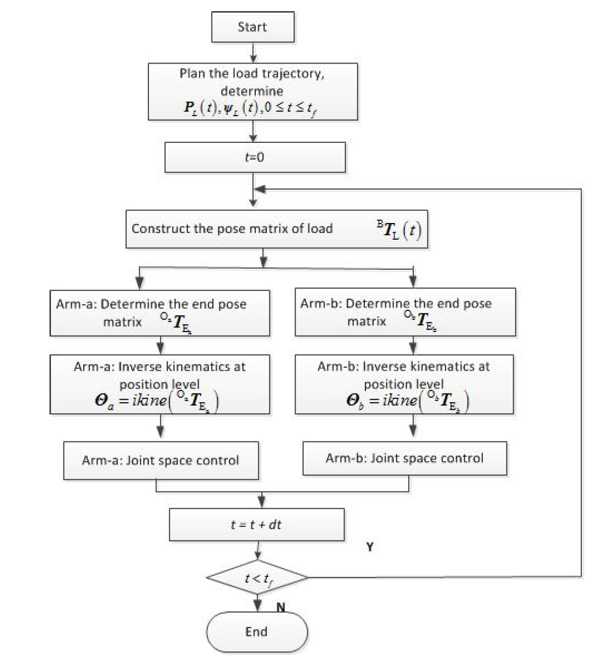
The algorithm flow is shown in Figure 7. The main steps of resolved motion position control (called RMPC) are as follows:
t=t+Δt.
if t<tf, return to b); otherwise, end.
Coordinated resolved motion rate control
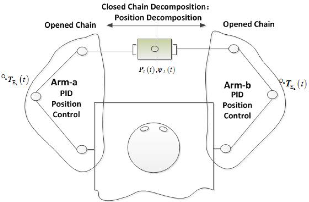
Coordinated position decomposition for a dual-arm manipulator
The process of coordinated position control for dual-arm manipulators
According to (24) and (25), we can control the coordinated movements of Arm-a and Arm-b using the resolved motion rate control (called RMRC) strategy. The algorithm flow is shown in Figure 8.
The main steps are as follows:
The process of coordinated velocity control for dual-arm manipulators


where, Δ

where,


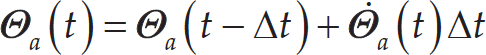
Correspondingly, we can obtain the joint angles as follows:
t=t+Δt.
if t<tf, return to b); otherwise, end.
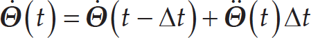
The idea of resolved motion acceleration control (called RMRC) strategy is to decompose the desired acceleration of the payload into the desired end accelerations of Arm-a and Arm-b respectively. Each manipulator is controlled by its own resolved motion law. The algorithm flow is shown in Figure 9.
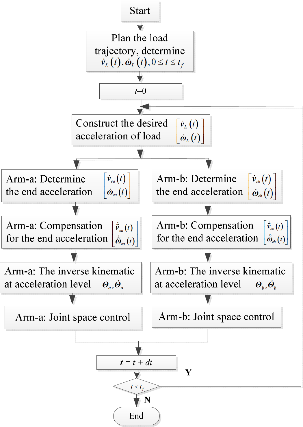
The process of coordinated acceleration control for dual-arm manipulators
The main steps are as follows:


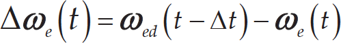
where, Δ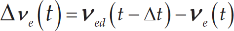


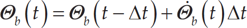
Correspondingly, we can obtain the joint velocities and angles as follows:

t=t+Δt.
if t<tf, return to b); otherwise, end.
ADAMS/Simulink co-simulation system
The co-simulation system of the Humanoid robot is established to test the proposed algorithm under typical coordinated tasks. The dynamic model is created in ADAMS software and the algorithms are realized in a Matlab/Simulink environment.
Coordinated resolved motion position control
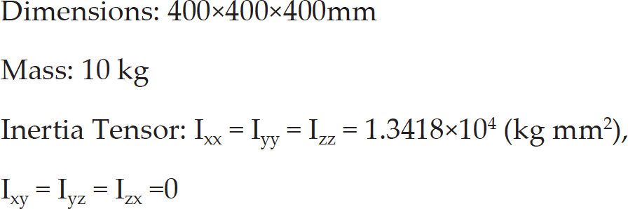
It is assumed that the payload is a cube, whose dimensions and mass are as follows:
Dimensions: 400×400×400mm
Mass: 10 kg
Inertia Tensor: Ixx = Iyy = Izz = 1.3418×10⁴ (kg mm2),
Ixy = Iyz = Izx = 0
Initially, the joint angles of each manipulator are known as (the unit is degrees):
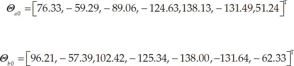
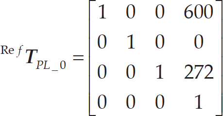
The initial position of the geometry centre of load is set to (600mm, 0, 272mm) and the attitude angles are (0, 0, 0) (x-y-z Euler angles) with respect to the body frame of the robot. The homogeneous transformation matrix is as follows:
The desired pose of the payload is denoted as:

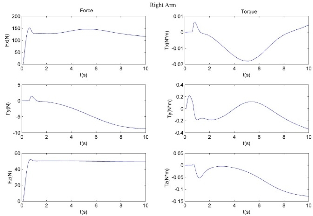
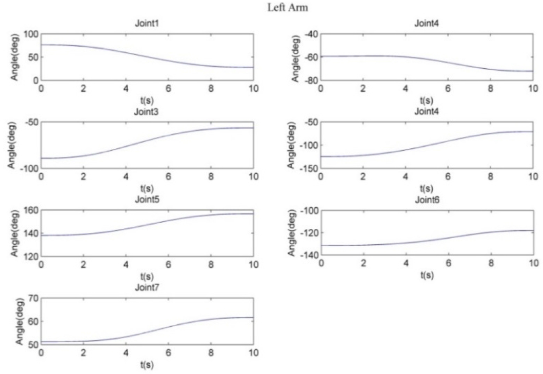
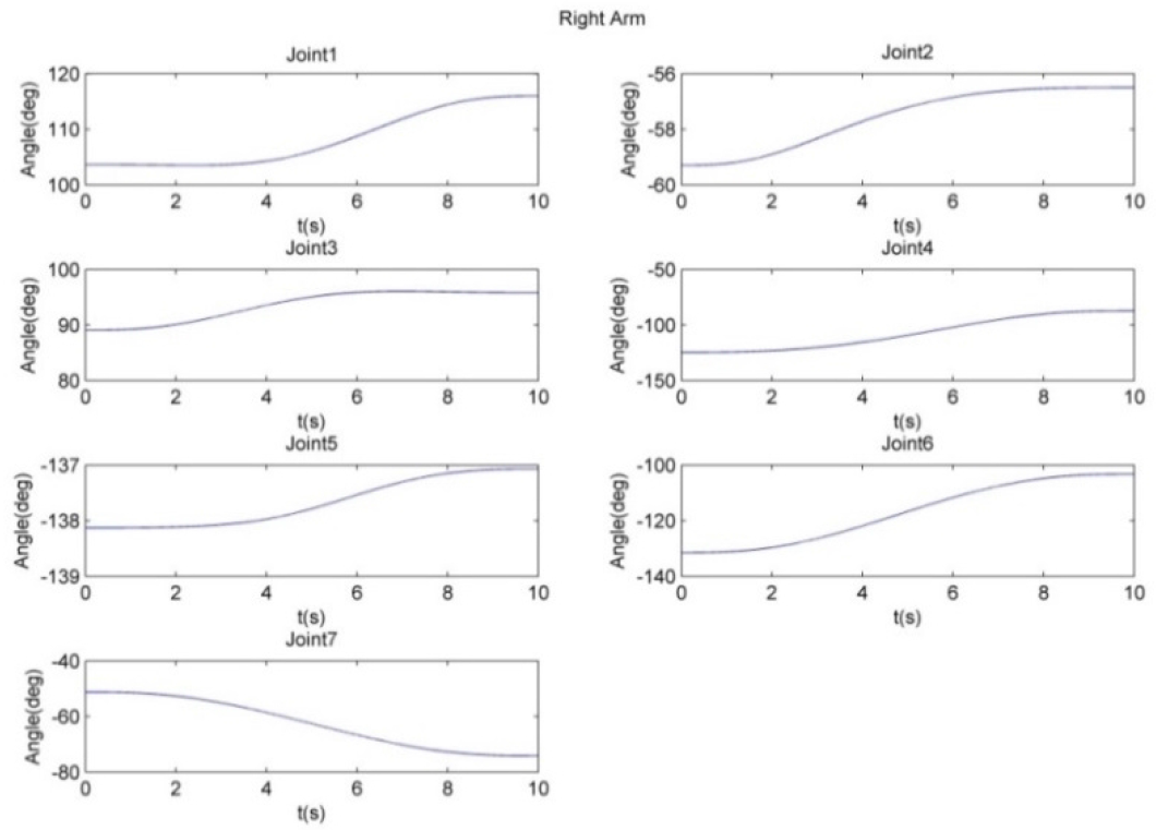
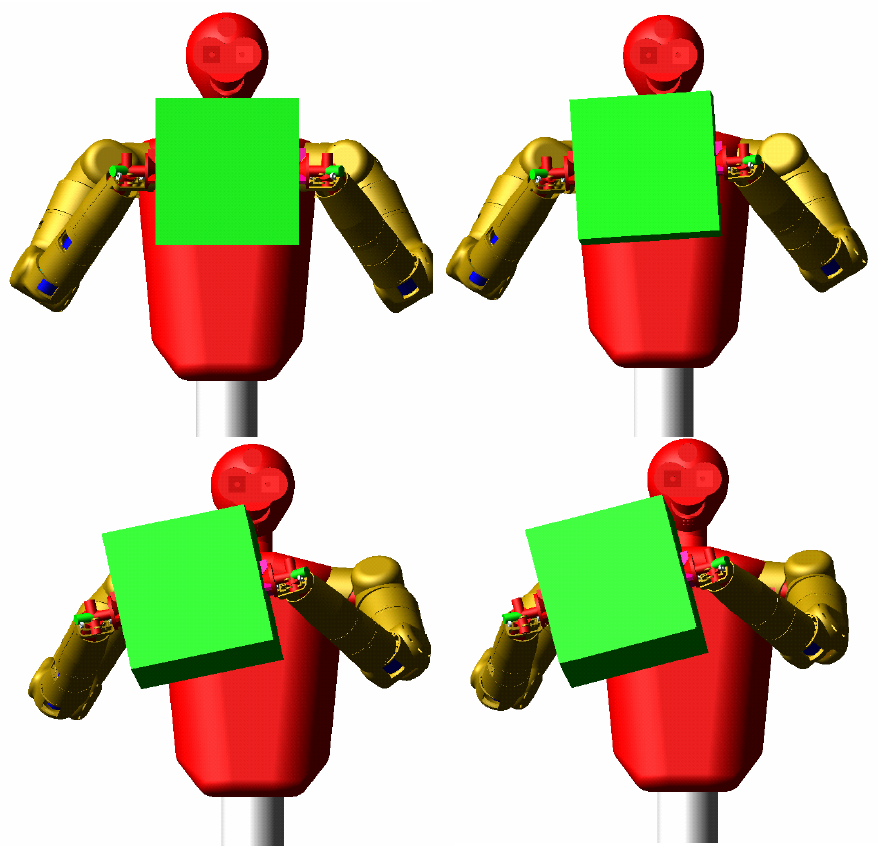
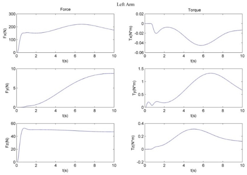
The P2P Cartesian trajectory of the geometry centre of the payload is planned with the movement time tf=10s using the 5th polynomial function. The two arms are then controlled to move the payload from the initial pose to the desired pose under the resolved motion position control strategy. During the simulation, the joint trajectories of the two arms are shown in Figure 10 and Figure 11 respectively. The whole simulation process is shown in Figure 12. The motion of the two arms is very smooth, showing that the control strategy is effective. We also evaluate the pose errors by analysing the simulation results. The maximum deviations in X, Y and Z direction are 0.005, 0.017 and 4.566 mm respectively. The average error is 1.523 mm. The largest attitude errors of Z-Y-X Euler angles are 0.025°, 0.046° and 0.012° respectively. The force and torque of the end-effector are also detected by the six dimensional force/torque sensors installed at the end of the two arms' manipulator. They are shown in Figure 13 and Figure 14.
The simulation results show that the dual-arm co-operation can be realized by coordinated resolved motion position control. The force along the X axis is the tensile force of the payload generated from the grasping of the three-fingers end-effector. The force along the Y axis, which mainly reflects the operational internal force, is small enough to be ignored. The forces along the Z axis of each arm counteract the gravity of load. The internal force generated during the dual-arm coordinated operation is acceptable.
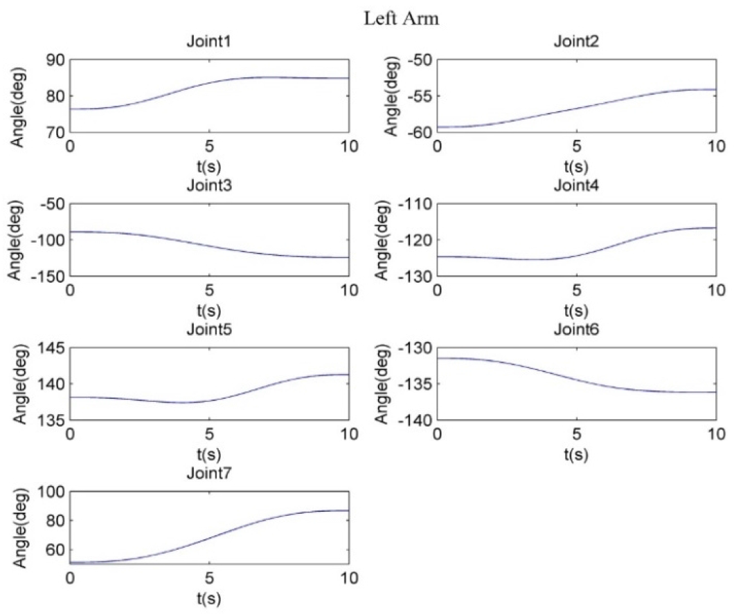
The joint angles of left arm

The joint angles of right arm
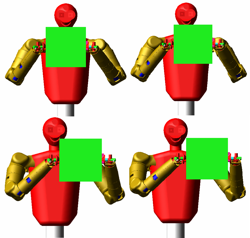
The movement process under resolved motion position control
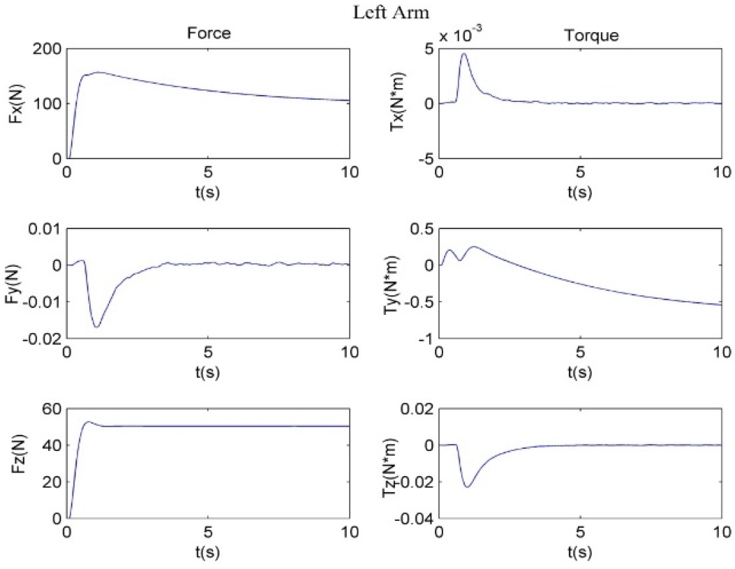
The end force/torque of left arm

The end force/torque of right arm
The initial pose of the payload with respect to the body frame of the robot is set to (600m, 0mm, 272mm; 0°, 0°, 0°) and the final pose of the load is (800mm, 0mm, 0mm; 5°, 10°, 0°). Similar to the simulation above, the P2P Cartesian trajectory of the geometry centre of the payload is planned with tf=10s, using the 5th polynomial function. The resolved motion rate control method is used for the humanoid robot. Then, the desired velocity of the end-effectors of the two arms can be derived from Eqs. (36) and (37).
According to the simulation results, the trajectories of each joint of the two arms are shown in Figure 15 and Figure 16. The movement process during the simulation is shown in Figure 17. The maximum position errors of the X, Y and Z axes are respectively [−0.5120mm, 0.2169mm, 5.560mm]. The largest attitude errors of X-Y-Z Euler angles are [−0.2712°, −0.5312°, 0.0123°]. The sensed end forces and torques of the two arms are shown in Figure 18 and Figure 19.

Joint angles of left arm
The simulation results show that the dual-arm co-operation can be realized by coordinated resolved motion rate control. The force along the X axis is the tensile force of the payload generated from the grasping of the three-fingers end-effector. The force along the Y axis, which mainly reflects the operational internal force, is no longer close to ON because of the integral error of velocity-level resolution. The forces along the Z axis of each arm counteract the gravity of load. The internal force generated during the dual-arm coordinated operation is acceptable.

Joint angles of right arm

The movement process under resolved motion rate control
The initial pose of the payload with respect to the body frame of the robot is set to (600m, 0mm, 0mm; 0°, 0°, 0°) and the final pose of the load is (800mm, 200mm, 0mm; 5°, 10°, 15°). The acceleration trajectory of the load is planned by the 5th polynomial function with t f = 10 s. Therefore, the desired end accelerations of Arm-a and Arm-b can be calculated by (46) and (47) using the resolved motion acceleration control method. The angle, angular velocity and angular acceleration of each joint can then be calculated by the inverse kinematics of each arm.
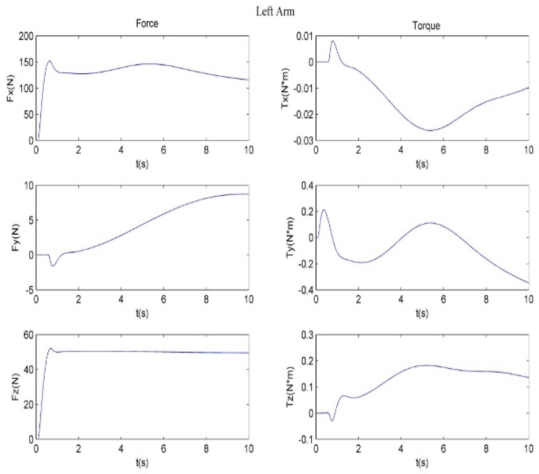
The end force/torque of left arm
The end force/torque of right arm
According to the simulation results, the trajectories of each joint of the two arms are shown in Figure 20 and Figure 21. The movement process during the simulation is shown in Figure 22. The maximum position errors of the X, Y and Z axes are respectively [−0.5281mm, 0.4825mm, 4.567mm]. The largest attitude errors of X-Y-Z Euler angles are [−0.0063°, −0.0207°, 0.0513°]. The sensed end forces and torques of the two arms are shown in Figure 23 and Figure 24.
The simulation results show that the dual-arm co-operation can be realized by coordinated resolved motion acceleration control. The force along the X axis is the tensile force of the payload generated from the grasping of the three-fingers end-effector. The force along the Y axis, which mainly reflects the operational internal force, is no longer close to ON because of the integral error of acceleration-level resolution. The forces along the Z axis of each arm counteract the gravity of load. The internal force generated during the dual-arm coordinated operation is acceptable.
The joint angles of left arm
The joint angles of right arm
The movement process under resolved motion acceleration control
The end force/torque of left arm

The end force/torque of right arm
In this paper, we present position-level, velocity-level and acceleration-level resolved motion control methods. The desired poses, velocities and/or accelerations of the payload are first planned according to the requirement of the task. Then, the poses, velocities and/or accelerations of the two arms' end-effectors are determined by resolving constraints on the two arms, which are connected by the payload and form a closed chain. The joint variables of each arm are then calculated using the inverse kinematics equations, at position-level, velocity-level or acceleration-level corresponding to the three cases. The simulation results verify the control algorithm based on a dynamic modelling and simulation platform established in ADAMS and Matlab/Simulink. The dual-arm coordinated manipulation can be realized by the proposed method in this paper and the internal force generated during the co-operation is acceptable. Therefore, the proposed control strategy provides a simple and effective way to realize dual-arm cooperation. In the future, we will experiment with the presented methods on a practical humanoid robot.
Footnotes
Acknowledgements
This work was supported in part by the National Natural Science Foundation of China under grant 61573116 and the Basic Research Programme of Shenzhen (JCYJ20140417172417095, JCYJ20150529141408781).