
Abstract
In order to solve the limitations of the friction pairs in axial piston pumps on rotational speed and mechanical efficiency, a 2D piston pump whose 2D piston has two-degree-of-freedom motions of rotation and reciprocating motion was proposed by the author team. The volumetric efficiency of 2D pumps predicted by the original volumetric efficiency model is higher than the experimental results. A new mathematical model of the volumetric efficiency is researched by considering effect of clearance between the cone roller and the guiding rail. In previous studies, the volumetric losses of the 2D pump were considered to be composed of leakage and compressibility loss. However, it is found that the effect of the clearance on the volumetric efficiency in 2D pumps is greater than that of leakage and compressibility loss. The experimental results show that the difference between the prediction of the new model and the volumetric efficiency of the tested pump with 0.19 mm clearance is reduced from 8% to 1.5% comparing with the original model. The volumetric efficiency of the tested pump without the clearance is 96.5% at 5000 rpm rotational speed and 8 MPa load pressure.
Introduction
Hydraulic systems are widely used in aeronautics and astronautics because of its high power-to-weight ratio.1,2 As the requirement for the power-to-weight ratio has increased in aeronautics, the hydraulic system that its power-to-weight ratio is determined by hydraulic components’ has been continuously updated, such as electro-hydrostatic actuator (EHA)-installed axial piston pumps as the oil source is used to replace the centrifugal hydraulic system which uses centrifugal pumps as the oil source.3,4 In recent years, due to the development of materials science, such as rubidium magnets, the power-to-weight ratio of motors has begun to increase rapidly, which makes the power-to-weight ratio of hydraulic components, especially for axial piston pumps, have higher challenges.5,6
The main method of axial piston pumps to increase the power-to-weight ratio is to increase the rotational speed. 7 When the load pressure and the required flow rate are constant, the increase in the rated rotational speed of the pump can reduce the displacement of the pump, thereby increasing the power-to-weight ratio by reducing the weight of the pump. 8 However, the rotational speed increasing in the axial piston pump is limited by the cavitation, tilting motion, and thermal problem.8–11 It is important that the three sliding friction pairs in the axial piston pump, such as the cylinder block/the valve plate, the pistons/the cylinder block, and the slipper/the swash plate, are all affected by the overturning moment.12–14 Especially at high rotational speeds, the rise in the overturning moment causes direct metal-to-metal contact between the sliding surfaces in the three main friction surfaces. 15
Since focusing on these shortcomings, many studies attempted to diminish the limitations for the rotational speed by the three friction pairs in axial piston pumps through abundant new structural designs of the pump’s components.16–18 The author team has been researching new hydraulic components, and successfully developed 2D hydraulic valves and 2D flow meters.19–21 Now combining the 2D principle with axial piston pumps, a new type of piston pump is proposed, named 2D piston pump.22–24 As shown in Figure 1, the core of 2D piston pumps is to convert the rotation of the 2D piston into the reciprocating motion of the 2D piston through the cooperation of the cone roller and the guiding rail. However, since the reciprocating motion of the 2D piston is designed as the uniform accelerated and decelerated motion, the alternate inertial force generated by the reciprocating motion of the 2D piston causes the pump to vibrate violently, especially when the mass of the moving set is large. 25
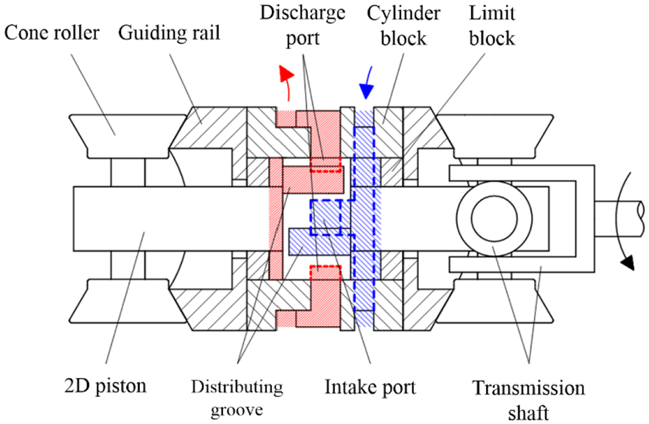
The traditional 2D piston pump. 25
In order to solve the problem of the vibration in the traditional 2D piston pump, the 2D piston pump with a balanced force is proposed and eliminates the vibration by adding a balancing set, as shown in Figure 2 that the orange is the driving set, and the blue is the balancing set. The 2D piston pump with a balanced force will be used as a fuel supply pump for aero engines in the aviation field. Its rated working rotational speed is 5000 rpm and load pressure is 8 MPa. Since the motions of the driving set and balancing set are opposite, the cylinder block is subjected to a pair of forces generated by the motions of the driving set and balancing set that their directions are opposite and magnitudes are same. Experiments prove that the 2D piston pump with a balanced force works smoothly at 5000 rpm rotational speed, so it has the potential for high rotational speeds. 25
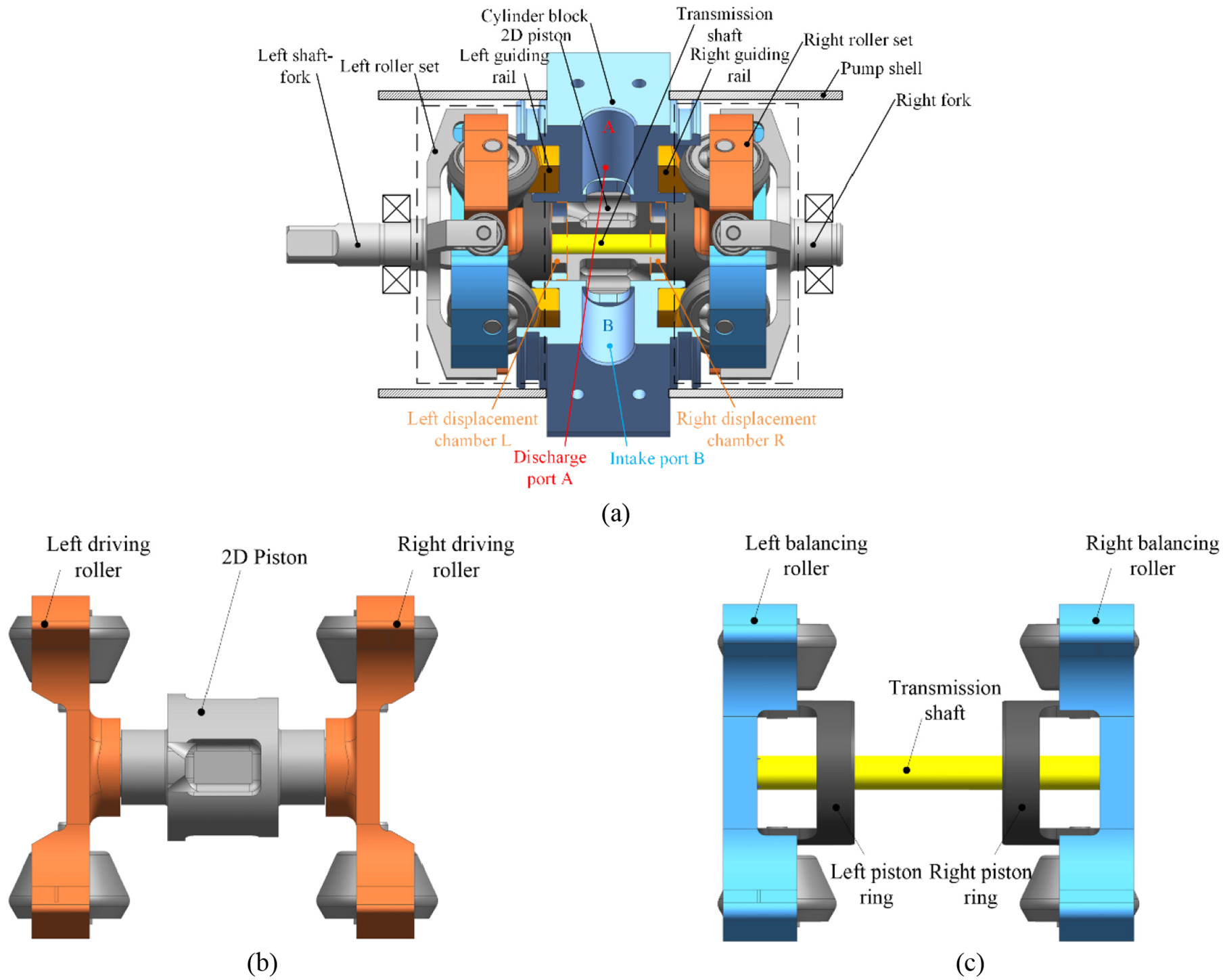
The 2D piston pump with a balanced force 26 : (a) the overview sight, (b) the driving set, and (c) the balancing set.
The volumetric efficiency of the 2D piston pump with a balanced force was researched by mathematical modeling, and volumetric losses containing backflow and leakage were analyzed and discussed from the perspectives of load pressures, rotational speeds, and gap sizes between the 2D piston and the cylinder block. 27 However, as shown in Figure 3, there is a difference between the experimental data and simulations, and the difference increases as the rises in the rotational speed and load pressure. Although the change in the size of the gap can make the simulations conform to the experimental results when the rotational speed is constant, this is obviously not convincing. After the test, it is found that there is a clearance between the cone roller and the guiding rail, so it is doubted whether this clearance has an impact on the volumetric efficiency. In recent years, researchers often focus on the leakage caused by the clearance, and analyze the flow field of the leakage by the Computational Fluid Dynamics (CFD).28–30 However, the displacement of the moving parts caused by the clearance is ignored, which affects the volumetric efficiency of the hydraulic pump.

Volumetric efficiency distributions of the experimental data and simulations at rotational speeds 27 : (a) 1000 rpm and (b) 3000 rpm.
This paper takes the driving set as an example to deeply analyze its clearance motion. Based on the backflow, a new volumetric loss generated by the clearance is proposed. Firstly, the new volumetric loss is added to the original mathematical model by re-mathematical modeling in Section 2. Then, this new volumetric loss is analyzed from multiple perspectives, such as rotational speeds, load pressures, and the clearance sizes, and the new simulation is compared with the original simulation in Section 3. Finally, a test bench is built to measure the volumetric efficiency of the tested pump with and without the clearance and verify the new mathematical model in Section 4.
Mathematical modeling
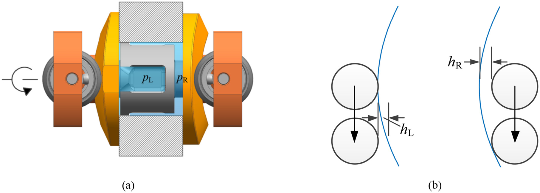
Because of machining accuracy, assembly errors, material deformation under load, and wear, there is a clearance between the cone roller and the guide rail. The rotational speed is assumed to be slow, and the motion of the clearance is driven by pressures of two chambers. As shown in Figure 4(a), the left chamber is at the end of discharging oil and the right chamber is at the end of sucking oil. The pressure pL in the left chamber is greater than the pressure pR of the right chamber, and the left cone roller is close to the left guide rail, and the clearance hR appears on the right. At the next moment, as shown in Figure 4(b), the left chamber starts to suck oil and the right chamber starts to discharge oil. Because the pressure in the right chamber rises rapidly and in the left chamber drops rapidly, the 2D piston moves to the left slightly and the clearance hL appears on the left. The change displacement xc of the clearance, which is assumed to be positive to the right, is described by the equation (1),

where Ap is the cross area of the 2D piston, mp is the mass of the driving set, Bp is the coefficient of viscous frictional force, and elastic load and Coulomb frictional force are unconsidered. The change acceleration


The motion of the clearance driven by pressures of two chambers: (a) initial state and (b) the motion of the clearance.
As shown in Figure 4(a), the state of the 2D piston is assumed to be at the initial state and the rotational angle is 0°. The clearance change velocity can be calculated by integrating equation (2), and the clearances hL(t) and hR(t) of the left and right over time are determined by the change displacement of the clearance, which can be described as follows.


When the load pressure is assumed to be 0 MPa, as shown in Figure 5(a), the motion of the clearance is no longer decided by pressure difference of two chambers but by rotation of the 2D piston. In order to better describe relationship between the motion of the clearance and rotation of the 2D piston, the motion of the cone roller on the guiding rail is expanded into a plane, as shown in Figure 5(b). Since the reciprocation of the 2D piston is a motion with uniform acceleration while the driving set rotating from the initial state to 45°, the motion of the clearance driven by rotation of the 2D piston is also the same. As the 2D piston rotates, the clearance on the left side increases with a uniform acceleration and the clearance on the right side decreases with a uniform acceleration, which can be described as follows,


where the acceleration a is the same as the acceleration of the 2D piston which is determined by the rotational speed n and the 2D piston stroke h, and can be calculated using equation (8) in Huang et al. 27

The motion of the clearance driven by rotation of the 2D piston: (a) initial state and top view and (b) the motion of the clearance.
By combining the equations (4)–(8), the motion of the clearance driven by pressure difference of two chambers and rotation of the 2D piston can be put forward as in equations (9) and (10).


Since volumes of two chambers are affected by the motion of the clearance, in the process of mathematical modeling, volumes of the two chambers need to be modeled separately. Assuming the oil in the left and right displacement chambers is compressible, the instantaneous left and right displacement chamber pressures are governed by the following pressure build up equations (11) and (12),


where βe is the bulk modulus of the oil, QoL is the outlet flow of the left displacement chamber, QiL is the inlet flow of the left displacement chamber, QLL is the leakage flow of the left displacement chamber, QoR is the outlet flow of the right displacement chamber, QiR is the inlet flow of the right displacement chamber, and QLR is the leakage flow of the right displacement chamber, above flows are described in Huang et al. 27
Because the volume VL of the left chamber and the volume VR of the right chamber are affected by the clearances on the left and right side, as shown in Figure 4(a), although the clearance appears on the right side, the volume of the left chamber is the sum of the designed minimum size Vmin of the chamber and the volume generated by the clearance. When the clearance of the left side is zero and the clearance of the right side is at maximum, the volume of the right chamber is the sum of the designed maximum size Vmax of the chamber and the volume generated by the clearance. In addition, when the clearance on the right side exceeds zero, the volumes of two chambers are decided by pressure difference of two chambers. When the right clearance is zero, the volumes of two chambers are decided by rotation of the 2D piston. Since the motion of the balancing set is also be affected by the clearance, the volumes of two chambers can be described by equations (13) and (14),


where hc is the maximum size of the clearance. Equations (15) and (16) are obtained through differentiating the equations (13) and (14).


When the left chamber starts to discharge oil, the laws of the clearance motion are similar, so this part of the modeling process is omitted. As the pump rotates a cycle, the left and right displacement chambers respectively discharge oil twice.
Finally, the curve of the pump’s discharging oil is obtained by solving above equations. All discharging flow can be calculated by integrating the outlet flow; then, volumetric efficiency η is obtained by comparing all discharging flow with the theoretical output flow,

where t360° is the time that the pump rotates from 0° to 360°, and VD is the pump’s displacement.
Simulation results
The volumetric efficiency considering the clearance of the 2D piston pump with a balanced force can be calculated by solving equations (1)–(17). According to Table 1, parameters needed by the simulation are consistent with the tested pump.
Main parameters of the simulation.

As shown in Figure 6, comparing simulations with clearance and without clearance, the backflow considered the clearance is much larger than that unconsidered one’s. As the increase in load pressure, the peak flow of the backflow obviously rises and the duration angle decreases. As shown in Figure 6(b), regardless of whether the clearance is considered or not, the backflow caused by the compressibility of the oil occurs at the beginning. Then, because the volume of the oil discharging chamber increased sharply, there is a larger backflow at simulations with the clearance. This shows that, when the clearance exists, the rise in load pressure causes the rise in the flow fluctuation.
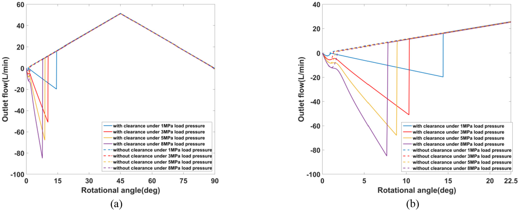
The outflow at load pressures 1, 3, 5, and 8 MPa for rotational angle ranges: (a) 0°–90° and (b) 0°–22.5°.
When load pressure rises, due to the increase in pressure difference between instantons pressure in chamber and pressure required to discharge oil, more backflow occurs. As shown in Figure 7, the existence of the clearance prevents the right chamber pressure from rising continuously.

The right chamber pressure at load pressures 1, 3, 5, and 8 MPa for rotational angle range 0°–90°.
The motion of the clearance is the key to the pressure change. Taking Figure 8 as an example, only when the left clearance is at its maximum, the right chamber pressure begins to rise, and the right chamber begins to discharge oil. If the clearance does not reach the maximum, the pressure in the right chamber cannot rise because the backflow continues to push the 2D piston to the left until the clearance reaches the maximum. As the rise in load pressure, the duration of the clearance motion decreases, but this does not mean that the volumetric efficiency increases.

The right chamber pressure and the motion of the left clearance at load pressures 1, 3, 5, and 8 MPa for rotational angle range 0°–22.5°.
As shown in Figure 9, when the rotational speed increases, since the peak flow of the backflow obviously rises, the rise in the rotational speed causes the rise in the flow fluctuation.

The outflow at rotational speeds of 1000, 3000, and 5000 rpm at angle ranges of: (a) 0°–90° and (b) 0°–22.5°.
When rotational speed rises, as shown in Figure 10, pressure difference between instantons pressure in chamber and pressure required to discharge oil decreases, but the peak flow of the backflow increase. Although the pressure difference at low rotational speed is large, as shown in Figure 9, the peak flow is small because the oil discharging area at the moment is small.

The right chamber pressure at rotational speeds of 1000, 3000, and 5000 rpm for rotational angle range 0°–22.5°.
As shown in Figure 11 that is similar to Figure 8, only when the left clearance is at its maximum, the right chamber pressure begins to rise, and the right chamber begins to discharge oil. Since, as the rotational speed increases, the clearance motion starts to be determined by rotation of the 2D piston rather than the pressure difference, the driving and balancing sets need to turn more angles to make the left clearance move to the maximum.

The right chamber pressure and the motion of the left clearance at rotational speeds of 1000, 3000, and 5000 rpm for rotational angle range 0°–22.5°.
As the rise in the clearance size, the peak flow of the backflow increases and the volumetric efficiency of the pump decreases in Figure 12(a). When the clearance size rises, the maximum pressure difference has not changed much, but the duration of the clearance motion has increased significantly.

The outflow, the right chamber pressure, and the motion of the left clearance at clearances of 0.1, 0.2, and 0.4 mm: (a) the outflow and (b) the right chamber pressure and the motion of the left clearance.
As the rise in the clearance size, the volumetric efficiency decreases significantly regardless of rotational speed and load pressure. As shown in Figure 13(a), in the simulation without considering the clearance, the volumetric efficiency decreases linearly with the increase in load pressure, while, in the simulation considering the clearance, the increase in the clearance size makes the volumetric efficiency decrease faster under low load pressures, and the decrease is consistent with the simulation without the clearance under high load pressures. However, as shown in Figure 13(b), the increase in the clearance size only decreases the volumetric efficiency with rotational speed increases.

The volumetric efficiency of the pump at clearances of 0.1, 0.2, and 0.4 mm: (a) at various load pressures and (b) at various rotational speeds.
Experimental results
As shown in Figure 14(b), the test rig consists of a tested pump, a torque sensor used to measure the input torque, a driving motor, a supply pump, a tank, two pressure sensors installed at the inlet and the outlet of the tested pump, a relief valve used to adjust the outlet pressure, a flow meter, and a data acquisition device. The accuracies of the related sensors are shown in Table 2.
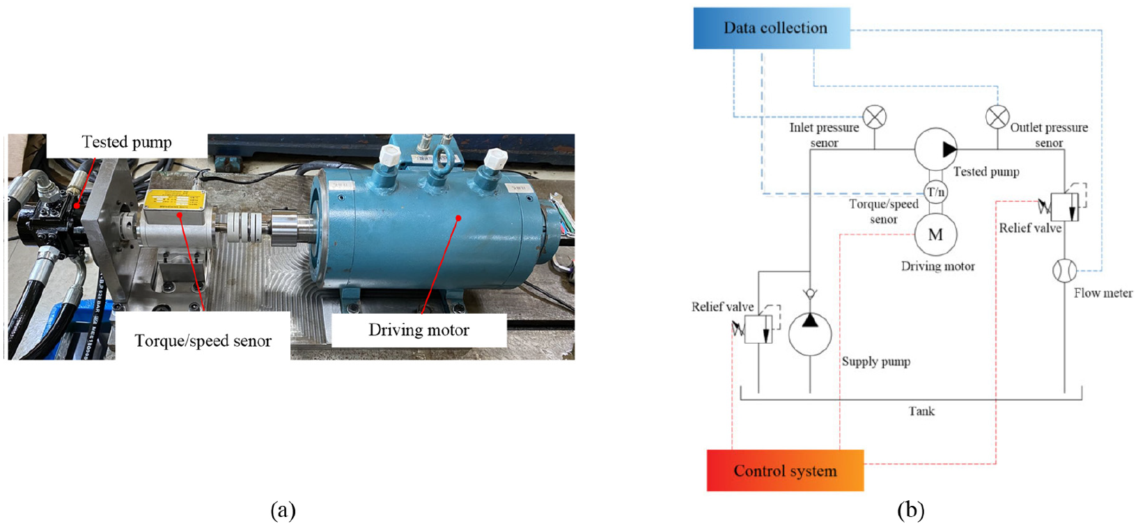
The test rig: (a) test platform and (b) test rig system.
The details of the related sensors.

In order to measure the clearance between the cone roller and guiding rail, when the pump does not rotate, the maximum clearance is achieved by pressurizing the oil outlet. Due to pressurizing the oil outlet, the chamber connecting with the oil outlet is distended by high-pressure oil, and the left or right clearance is fixed at the maximum. As shown in Figure 15, the maximum clearance measured is 0.19 mm by using a filler gage.
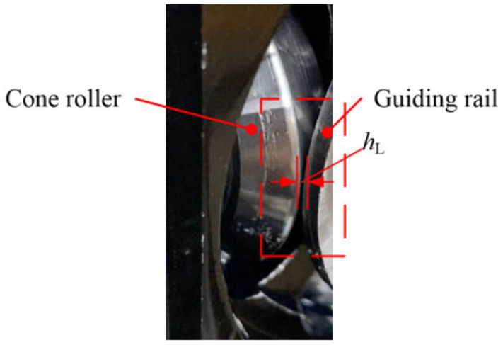
The clearance between the cone roller and guiding rail.
Comparing the theoretical flow, experimental data, simulation without clearance, and simulation with 0.19 mm clearance, as shown in Figure 16, the degree of fit between simulation with 0.19 mm clearance and experimental data is much greater than that of simulation without clearance. The difference between the simulation with the clearance and experimental data has been reduced from 8% to 1.5% comparing with that of the simulation without clearance at different rotational speeds and the 8 MPa rated load pressure.

Average outlet flow and volumetric efficiency at various rotational speeds: (a) average outlet flow and (b) volumetric efficiency.
In order to further demonstrate the mathematical model and increase the volumetric efficiency of the pump, as shown in Figure 17, the clearance can be reduced by tightening the ball nut. After tightening the ball nut, the filler gage cannot be inserted into the clearance, which can be considered to be less than 0.01 mm.

Ball nut position in the pump.
The volumetric efficiency of the tested pump without the clearance is much higher than that of the tested pump with 0.19 mm clearance, as shown in Figure 18, which proves that the volumetric efficiency of the 2D pump is high. Although there is the difference between the simulation without clearance and test without clearance, the difference is maintained at 1.5%. There are three explanations for the difference.

Volumetric efficiency at various: (a) rotational speeds and (b) load pressures.
Firstly, although high-precision machining is used to ensure the size of the gap between the 2D piston and cylinder block designed to be 0.02 mm during the machining process, errors remain in the gap because of the inevitable machining errors and wear, which causes the increase in leakage.
Secondly, as other studies have shown, at high rotational speeds, the friction and churning loss in the pump exacerbate the increase in oil temperature and reduce the oil viscosity, resulting in leakage increasing.26,31
Thirdly, when rotational speed increases, the 2D piston may be eccentric in the cylinder block, which causes the increase in leakage.
The increases in the above-mentioned three kinds of leakages reduce the volumetric efficiency, thus there is a difference between the simulation and the experimental data.
Conclusions
In this paper, the effect of the clearance between the cone roller and the guiding rail is considered in the volumetric efficiency of 2D piston pumps, which is studied through mathematical modeling. The mathematical model of the volumetric efficiency under the influence of the clearance is analyzed, from load pressures, rotational speeds, and clearance sizes, and compared with the model that does not consider the effect of the clearance. The volumetric efficiencies of tested pumps with and without the 0.19 mm clearance are measured separately, and compared with the simulation results. According to the experimental results, the following conclusions can be drawn:
In previous studies, the volumetric losses of the 2D pump were considered to be composed of leakage and compressibility loss. However, it is found that the effect of the clearance on the volumetric efficiency in 2D pumps is greater than that of leakage and compressibility loss. The clearance reduces the volumetric efficiency by increasing the backflow, and its existence seriously affects the improvement of the volumetric efficiency.
In 2D pumps, leakage and compressibility loss only increase with the load pressure increasing. So raising the rotational speed can reduce the influence of leakage and compressibility loss on the volumetric efficiency. The effect of the clearance on the volumetric efficiency cannot be reduced by increasing rotational speed, but it not increases with the increase in load pressure. The effect of the clearance on the volumetric efficiency is constant and only is determined by the size of the clearance.
When the clearance is eliminated, the volumetric efficiency of 2D pumps is high. The experimental results show that the volumetric efficiency of the tested pump with 0.19 mm clearance is 91.5% at 5000 rpm rotational speed and 8 MPa load pressure, and the volumetric efficiency of the tested pump without clearance is 96.5% under the same conditions.
Although the clearance can be eliminated by tightening the ball nut, this greatly increases the mechanical loss of the pump, and with wear, the clearance will occur again. Next, the relationship between the fastening force and the mechanical efficiency of the 2D pump will be studied, so that the mechanical efficiency and volumetric efficiency of the 2D pump can reach a higher level. Therefore, it is important to develop a 2D pump without the clearance. In addition, in order to increase rotational speed and reduce mechanical losses, the contact theory between the cone roller and the guide rail needs to be further studied.
Footnotes
Handling Editor: James Baldwin
Author contributions
Formal analysis, S.L.; data curation, Y.H.; writing – original draft preparation, Y.H.; writing – review and editing, C.D.; funding acquisition, J.R.
Declaration of conflicting interests
The author(s) declared no potential conflicts of interest with respect to the research, authorship, and/or publication of this article.
Funding
The author(s) disclosed receipt of the following financial support for the research, authorship, and/or publication of this article: This research was funded by the National Key Research and Development Program of China, grant number 2019YFB2005201, and by the National Natural Science Foundation of China, grant number 51805480, 51975524.