
Abstract
To address the drawbacks of traditional hydraulic power units, we embedded a 2D piston pump inside the motor rotor, proposing a 2D piston electro-hydraulic pump. The space cam mechanism serves as the primary force-bearing structure during its operation. Excessive wear occurs at the highest point of the space cam when subjected to significant axial forces, which leads to deviations between the motion law of the 2D piston and the theoretical design. Aiming this problem, we conduct research from two perspectives: theoretical analysis and fluid-structure interaction. Firstly, the operational principle of the electro-hydraulic pump is introduced. Then, the contact normal stress of the space cam mechanism is studied, and backflow and chamber pressure overshooting are discussed. Finally, the fluid-structure interaction model of the electro-hydraulic pump is established. Based on the fluid-structure interaction model, the effects of the width and depth angles of the triangular damping groove on the backflow and chamber pressure overshooting are analyzed. The simulation results demonstrate that adding triangular damping grooves can improve the flow field characteristics. With the increase in the width and depth angles, the peak flow of the backflow and chamber pressure overshooting increase, with the depth angle exerting a more pronounced effect.
Keywords
Introduction
Hydraulic systems offer several advantages, including flexibility in arrangement, a high power-to-weight ratio, favorable lubrication conditions, and reliability. Therefore, they find widespread applications in various fields such as engineering machinery, agricultural equipment, the energy sector, and aerospace.1–4 A typical hydraulic system comprises power units, control units, actuating units, auxiliary units, and working fluids. A traditional hydraulic power unit features a “three-stage” structure composed of an axial-series electric motor, coupling, and hydraulic pump connection. This structure presents drawbacks, including a sizeable axial footprint, low energy efficiency, and susceptibility to cause vibration and noise.5,6 To address these issues, scholars have proposed the effective solution of the electro-hydraulic pump. It integrates the electric motor, coupling, and pump into a compact and fully integrated unit, with the electric motor directly driving the hydraulic pump’s operation. It aligns with the developmental trends of hydraulic systems, emphasizing efficiency, energy conservation, and integration. 7
In recent years, scholars have researched various aspects of electro-hydraulic pumps, including their structure, efficiency, temperature field distribution, and flow characteristics. Ji et al.8,9 and Li et al. 10 investigated electric motor vane pumps’ flow field and distribution window. They provided insights into the design of distribution structures in electro-hydraulic pumps. Fu et al.11,12 proposed an axial piston electro-hydraulic pump. They calculated power losses and conducted finite element analysis on temperature and flow fields. Gao et al. 13 established a mathematical model for the fluid-solid heat transfer in axial piston electro-hydraulic pumps and elucidated the temperature rise patterns in this electro-hydraulic pump. Zhu et al. 14 proposed a double-swash plate hydraulic axial piston electric motor pump. They established a mathematical model for the distribution mechanism, analyzed the impact of structural and operational parameters on distribution characteristics, and verified the feasibility of this electro-hydraulic pump. The above research primarily focused on coupling traditional hydraulic pumps with electric motors, effectively addressing the shortcomings of traditional hydraulic power units. However, these electro-hydraulic pumps retained the disadvantages of pump body structure and operational principles even after integration.
Due to their differing operational principles, hydraulic pumps can be categorized into gear, vane, and axial piston pumps. Among these, axial piston pumps are the most aligned with the high-pressure, high-speed, and high power-to-weight ratio development direction. The primary method for increasing the power-to-weight ratio is to elevate the rotational speed. However, in axial piston pumps, due to the presence of three sliding friction pairs: the cylinder block/the valve plate, the pistons/the cylinder block, and the slipper/the swash plate, operating at high speeds can lead to an increase in overturning moments. Which results in direct metal-to-metal contact on the frictional component surfaces, ultimately diminishing their mechanical efficiency. 15
In response to the issue of hydraulic pump friction pairs being constrained by the highest PV values, Professor Ruan’s research team researched and invented the 2D piston pump16–18 and studied its space cam mechanism and flow field characteristics. Compared to traditional axial piston pumps, the 2D piston pump offers advantages such as a smaller size, lighter weight, compact structure, and greater suitability for integrated design. The authors combined the 2D piston pump with the principles of electro-hydraulic pumps to design and develop the 2D piston electro-hydraulic pump, as shown in Figure 1(a). The 2D piston electro-hydraulic pump comprises the motor and pump body parts, with the pump body’s structure shown in Figure 1(b). Its operational principle involves transferring motor torque through the coupling to the 2D piston. Constrained by the space cam, the 2D piston simultaneously undergoes rotational and reciprocating axial motion. This motion causes the volumes of the intake and discharge oil chamber and the distribution area to change, achieving the pump’s oil intake and discharge functions.

2D piston electro-hydraulic pump structure: (a) electro-hydraulic pump and (b) pump body.
The 2D piston electro-hydraulic pump has four distribution grooves: J, K, L, and M, located on the shoulder of the 2D piston. The distribution grooves J and K are connected to the right oil chamber, while L and M are connected to the left oil chamber. These four distribution grooves interact with oil inlet distribution windows A and B and oil outlet distribution windows C and D during the 2D piston rotation. The distribution status during one-quarter of the working cycle is shown in Figure 2.

The electro-hydraulic pump distribution status at various rotational angles: (a) 0 deg, (b) 30 deg, (c) 60 deg, and (d) 90 deg.
The performance characteristics of the 2D piston electro-hydraulic pump are determined by the motion law of the space cam. As shown in Figure 3, the acceleration motion law of the space cam is composed of constant acceleration, B-spline transition, and constant deceleration phases. Notably, the B-spline transition phase is difficult to describe by the formula; therefore, this study employs a bidirectional fluid-structure interaction approach to enhance the fidelity of simulating the electro-hydraulic pump’s operation, with the computational workflow shown in Figure 4.

Acceleration curve of space cam.

Computational workflow of bidirectional fluid-structure interaction.
The space cam mechanism serves as the primary force-bearing structure and determines the motion law of the 2D piston. When the cone roller rotates to the highest point of the space cam, the intake oil chamber will switch to discharge oil condition, and the discharge oil chamber will switch to intake oil condition. The pressure difference between the discharge oil chamber and outlet led to the backflow and the chamber pressure overshooting. As shown in Figure 5, at each chamber condition switching, the pressure in the intake and discharge oil chambers undergoes abrupt variation, leading to a more significant pressure difference between the intake and discharge oil chambers.

Outlet flow and chamber pressure at load pressure of 12 MPa: (a) outlet flow and (b) chamber pressure.
For the space cam mechanism, a sudden increase in the pressure difference between the intake and discharge oil chambers causes the space cam to be subjected to greater force. When the space cam mechanism works under excessive force for a long time, it will experience excessive wear at the highest point, which affects the 2D piston motion accuracy. As shown in Figure 6, after wear occurs on the space cam, the displacement of the 2D piston exhibits a sudden change when rotating by 90 deg. When the wear is severe, it leads to axial endplay of the 2D piston, causing pronounced vibration, impact, and noise in the space cam mechanism.

Displacement curve of 2D piston: (a) 0–360 deg and (b) 70–110 deg.
To solve this problem, we analyze the outlet flow and chamber pressure variation of the 2D piston electro-hydraulic pump from the perspectives of theoretical and fluid-structure interaction numerical simulations. By adding a triangular damping groove on one side of the distribution window, the backflow and chamber pressure overshooting are limited. Firstly, the backflow and chamber pressure overshooting are researched from the theoretical aspect in Section “Theoretical analysis.” Then, the fluid-structure interaction model of the electro-hydraulic pump is established in Section “The fluid-structure interaction model.” Finally, the effects of the triangular damping groove structural parameter on the flow field characteristics of the electro-hydraulic pump are discussed based on the fluid-structure interaction model in Section “Simulation results.”
Theoretical analysis
When the left cone roller rotates the highest point of the left space cam, the operation of the 2D piston electro-hydraulic pump is shown in Figure 7. The velocity of the 2D piston is directed to the right and approaches zero in magnitude, while the acceleration is directed to the left, and the magnitude is determined by the motion law of the space cam. At this time, the working conditions of the left and right oil chambers have not changed. The left oil chamber remains in a low-pressure condition, and the right oil chamber remains in a high-pressure condition. The 2D piston is subjected to the right-to-left hydraulic pressure F p , which can be described by equation (1).

Where D is the major diameter of the 2D piston, d is the minor diameter of the 2D piston, P R is the pressure in the right oil chamber (high-pressure chamber), and P L is the pressure in the left oil chamber (low-pressure chamber).

The 2D piston electro-hydraulic pump operation when the left cone roller at the highest point of the left space cam.
As shown in Figure 8, the 2D piston is subjected to hydraulic pressure F p and inertia force F i in the axial direction. These forces manifest as a uniform pressure F acting on the contact line between the cone roller and the space cam. The contact situation of the space cam mechanism can be equated to the contact between two cylinders. According to the Hertzian contact theory, the contact normal stress between the cone roller and the space cam can be described by equation (2).

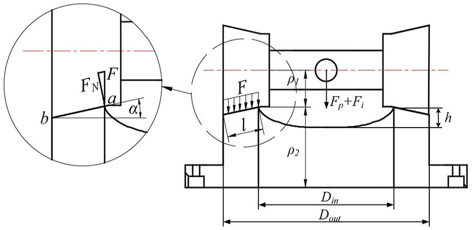
Contact scenario of the space cam mechanism during switching of operating conditions.
Where E is the elastic modulus of the cone roller and the space cam materials, l is the length of the contact line, ρ1 is the curvature radius of the cone roller at the analyzed point on the contact line, ρ2 is the curvature radius of the space cam at the analyzed point on the contact line, and F N is the normal pressure on the contact line. F N can be described by equation (3).

Where α is the cone top angle of the cone roller. Along the direction of the contact line, ρ1 and ρ2 gradually increase from point a to point b. According to equation (2), with the increase in ρ1 and ρ2, the contact normal stress decreases; thus, the point a on the inner side of the space cam is subjected to the maximum contact normal stress. The contact normal stress is related to the axial force, the curvature radius of the cone roller and the space cam, material properties, and contact line length. When the space cam mechanism’s geometric structure and material properties are determined, the contact normal stress is determined by the hydraulic pressure within the axial force.
Assuming the oil of the oil chamber can be compressed and expanded, according to the definition of the oil bulk modulus and the continuity equation, the pressure variation in the discharge oil chamber can be described by equation (4). 19

Where P d is the pressure in the discharge oil chamber, V t is the volume of the chamber, β e is the bulk modulus of the oil, q l is the leakage flow in the discharge oil chamber, and q i is the outlet flow. q i can be described by equation (5). 20

Where C o is the flow coefficient, A o is the distribution area, ρ is the oil density, and P o is the outlet pressure (load pressure). Equation (4) shows that the pressure variation in the discharge oil chamber is primarily determined by the change in chamber volume and outlet flow. The change in chamber volume is determined by the movement velocity of the 2D piston. When the chamber condition is switched, the movement velocity of the 2D piston is zero, so the chamber pressure is determined by the outlet flow. At this time, the chamber pressure has not yet reached the outlet pressure (P d < P o ), resulting in negative q i values and backflow. Due to the small distribution area of the 2D piston electro-hydraulic pump during the chamber condition switching, oil intake becomes difficult. The continuous movement of the 2D piston causes compression and expansion of the oil, resulting in chamber pressure overshooting. According to equation (5), the backflow is related to the distribution area. Reducing the distribution area during chamber condition switches can suppress backflow.
To analyze the distribution area of the electro-hydraulic pump over a 1/4 rotation cycle, the author expands the 2D piston along the circumferential direction. Figure 9 shows the distribution states under different rotational angles. In the figure, ω is the angular velocity of the 2D piston, L is the length of the distribution window, W is the width of the distribution window, A is the width of the distribution groove, and x is the arc length on the 2D piston major diameter corresponding to the rotational angle. When the rotational angle is from 0 to 30 deg, the distribution area increases linearly to the maximum value; when the rotational angle is from 30 to 60 deg, the distribution area keeps the maximum value unchanged; when the rotational angle is from 60 to 90 deg, the distribution area decreases linearly to zero. The distribution area of the oil outlet distribution windows can be calculated by equation (6).
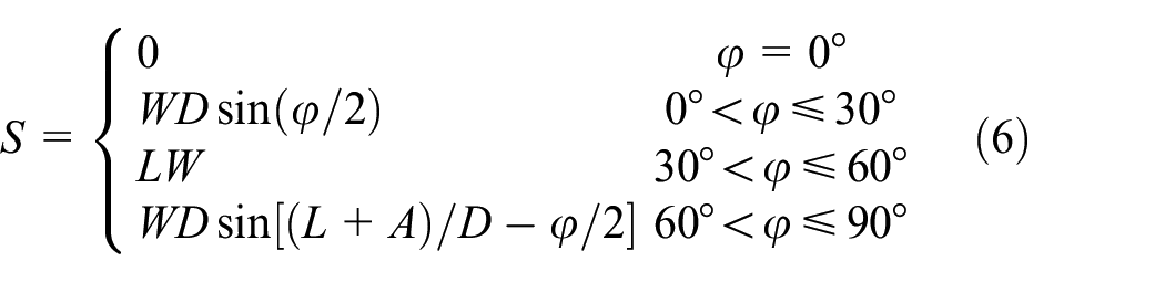
Where φ is the rotational angle of the 2D piston.
Distribution states at various rotational angles: (a) 0 deg, (b) 0–30 deg, (c) 30–60 deg, and (d) 60– 90 deg.
In traditional axial piston pumps, the issues of cavitation and backflow during the high-to-low pressure switching in the piston chamber are addressed by adding the damping groove on the distribution plate. The damping groove serves the purpose of pre-pressurization and pre-depressurization. However, in the 2D piston electro-hydraulic pump, the distribution grooves are located on the 2D piston, which undergoes a combined motion of rotation and axial movement. To ensure that the damping grooves work during each switching of the chamber conditions, they are added on one side of the distribution window. The type of damping groove is the triangular damping groove, 21 commonly used in axial piston pumps, and its structure is shown in Figure 10.
Triangular damping groove structure.
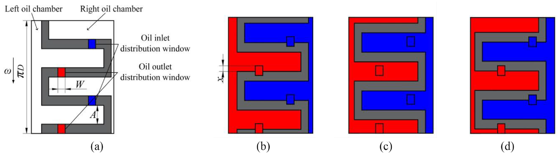
When the arc length on the major diameter of the 2D piston corresponding to the rotational angle is L2, the distribution groove is connected to the triangular damping groove; thus, the distribution area is the flow area of the smallest flow surface Δefi corresponding to Δefg. Let the angle between Δefg and Δefi be θ, then the area of Δefi can be calculated by equation (7).
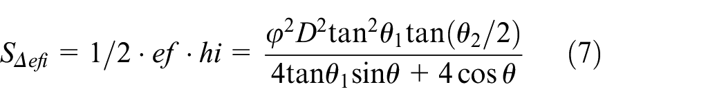
Where θ1 is the depth angle of the triangular damping groove, and θ2 is the width angle. When the structural parameters of the triangular damping groove are determined, to minimize the area of Δefi, the denominator in equation (7) should take the maximum value. When θ = θ1, the minimum flow area of Δefi can be calculated by equation (8).

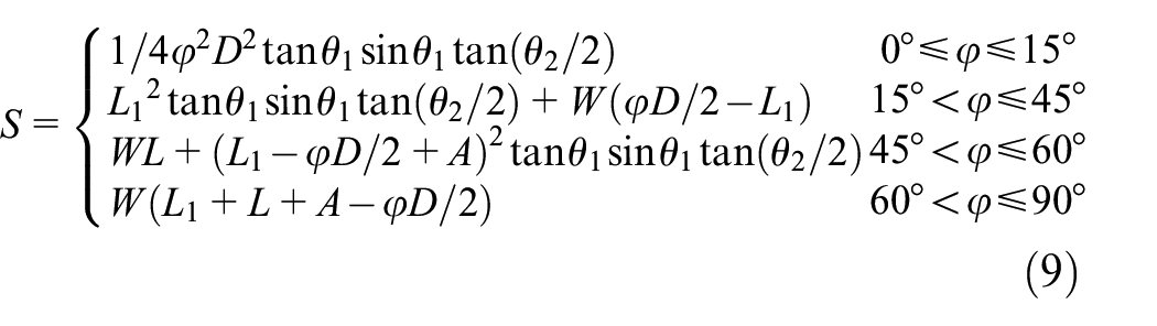
After adding the triangular damping grooves, the distribution states of the electro-hydraulic pump are shown in Figure 11. When the rotational angle is from 0 to 15 deg, the distribution area is the flow area of the triangular damping groove, and it increases gradually; when the rotational angle is from 15 to 45 deg, the distribution area increases linearly; when the rotational angle is from 45 to 60 deg, the triangular damping groove gradually withdraws from the flow distribution, and the distribution area decreases gradually; when the rotational angle is from 60 to 90 deg, the distribution area decreases linearly to zero. After adding the triangular damping groove, the distribution area can be calculated by equation (9).

Distribution states adding the triangular damping groove at various rotational angles: (a) 0–15 deg, (b) 15–45 deg, (c) 45–60 deg, and (d) 60–90 deg.
Combining equations (6) and (9), taking θ1 = 14 deg and θ2 = 100 deg, the change in distribution area without and adding the triangular damping groove is shown in Figure 12. Adding the triangular damping groove can reduce the distribution area when the backflow occurs. Combining equations (4), (5), and (8), it can be concluded that with the increase in width angle and depth angle, the flow area of the triangular damping groove increases; thus, the outlet flow and the chamber pressure overshooting increase.

Change in distribution area without and adding the triangular damping groove.
The fluid-structure interaction model
The control equations
Under unsteady conditions, the fundamental control equations for the fluid field include the mass conservation equation (the continuity equation) and the momentum conservation equation, which can be described by equations (10) and (11). 22


Where ρ is the fluid density, t is the time, u is the velocity vector, u x , u y , and u z are the velocity components of vector u in the x, y, and z directions, respectively, P is the pressure, τ ij is the stress tensor, g is the acceleration due to gravity.
The control equation for the solid field can be described by equation (12). 23
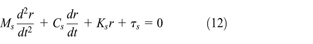
Where M s is the mass matrix, C s is the damping matrix, K s is the stiffness matrix, r is the displacement of the solid, and τ s is the stress experienced by the solid.
The geometric model
This paper focuses on the numerical simulation analysis of the pump body part in the 2D piston electro-hydraulic pump. In order to simplify the calculation, the motor part of the electro-hydraulic pump is omitted. The pump body structure of the electro-hydraulic pump was modeled using SolidWorks software, and the model of the pump body was imported into the Workbench platform for Boolean subtraction operations, which involved flow channel extraction to obtain the fluid domain model. The geometric model is shown in Figure 13.

Geometric model: (a) solid domain and (b) fluid domain.
Mesh generation and independence verification
In the solid domain, the space cam surface in the electro-hydraulic pump is the B-spline surface, and it determines the motion law of the 2D piston. A tetrahedral mesh is chosen for the solid domain because it has better adaptability than hexahedral mesh. In the fluid domain, the dynamic mesh technique is used to simulate the change of the flow field in the electro-hydraulic pump, and the fluid domain model is an irregular shape, so the tetrahedral mesh is also chosen for the fluid domain mesh. Then, independence is verified for meshes in the fluid and solid domains.
In the solid domain, mesh independence is verified by varying the number of meshes, using the Von Mises Stress of the space cam as the verification criterion. Figure 14(a) shows that when the number of meshes reaches 380,000, the numerical solution deviation of two neighboring times is 3.6%. The influence of the solid domain mesh on the calculation results is in the acceptable range, and the verification is completed. According to the verification results, the primary size of the solid domain mesh is 1 mm, and the mesh size of the space cam model is encrypted to 0.8 mm. Figure 14(b) shows the solid domain mesh.

Solid domain meshing: (a) mesh independent verification and (b) mesh model.
In the fluid domain, mesh independence is verified by varying the mesh size, using the flow channel pressure drop as the verification criterion. Figure 15(a) shows that when the mesh size is reduced to 0.4 mm, the numerical solution deviation of two neighboring times is 0.9%. The influence of the fluid domain mesh on the calculation results is in the acceptable range, and the verification is completed. According to the verification results, the primary size of the fluid domain mesh is 0.4 mm. Figure 15(b) shows the fluid domain mesh.

Fluid domain meshing: (a) mesh independent verification and (b) mesh model.
Boundary conditions
The solid domain boundary conditions include applying the motion vices for the model based on the working principle of the electro-hydraulic pump and setting the fluid-structure interaction interfaces, as shown in Figure 16. Figure 16(a) shows the frictional contact between the cone roller and the space cam with a friction coefficient of 0.1; Figure 16(b) shows the fixed vices between the space cam and the ground, between the cylinder and the ground, and between the 2D piston and the roller shaft, which restrict all degrees of freedom between these three pairs of motion vice; Figure 16(c) shows the cylindrical vices between the 2D piston and the ground and between the 2D piston and the cylinder, which enable the 2D piston to perform the combined motion of rotation and axial movement based on the Z-axis; Figure 16(d) shows the revolute vices between the cone roller and the roller shaft, which enable the cone roller rotates around the roller shaft; Figure 16(e) shows the rotational velocity of the 2D piston; and Figure 16(f) show the fluid-structure interaction interfaces in the solid domain.

Solid domain boundary conditions: (a) frictional contact, (b) fixed vices, (c) cylindrical vices, (d) revolute vices, (e) rotational velocity, and (f) solid domain fluid-structure interaction interfaces
The fluid domain boundary conditions include setting the oil inlet and outlet, fluid-structure interaction interfaces, fluid interaction interfaces, and dynamic mesh, as shown in Figure 17. Figure 17(a) shows the oil inlet and oil outlet; Figure 17(b) shows the fluid-structure interaction interfaces in the fluid domain, with its dynamic mesh set up as coupling motion; Figure 17(c) shows the fluid interaction interfaces, which is used for oil interaction, with its dynamic mesh set up as cylindrical deformation; Figure 17(d) shows the inner cylindrical surface in the oil chamber, with its dynamic mesh set up as cylindrical deformation.

Fluid domain boundary conditions: (a) oil inlet and outlet, (b) fluid domain fluid-structure interaction interfaces, (c) fluid interaction interfaces, and (d) cylindrical deformation surfaces.
The fluid domain computation is set as an incompressible flow field, and the Coupled velocity-pressure algorithm is employed to obtain a solution. The SST k-ω turbulent flow model is also employed.
Simulation results
The main parameters of the simulation are shown in Table 1. In this simulation, the effect of the triangular damping groove parameter on the flow characteristics of the electro-hydraulic pump is investigated.
Main parameters of the simulation.

The width angle θ2
As shown in Figure 18, as the width angle increases, the peak flow of the backflow increases, and the backflow occurs earlier. Due to the increase in the width angle, the flow area of the triangular damping groove increases, which causes an increase in the distribution area when the intake and discharge chamber conditions are switched; thus, more oil backs up into the low-pressure chamber.

Outlet flow at width angles of 60, 70, 80, 90, and 100 deg for rotational angle range of: (a) 0–360 deg and (b) 0–90 deg.
As shown in Figure 19, as the width angle increases, the value of chamber pressure overshooting increases. During the chamber condition switching, as the width angle increases, more oil in the left oil chamber, which is in the high-pressure condition, flows out through the triangular damping groove, causing an increase in the magnitude of the chamber pressure drop. For the right oil chamber, as the width angle increases, the magnitude of the chamber pressure increases.

Left oil chamber pressure at width angles of 60, 70, 80, 90, and 100 deg for rotational angle range of: (a) 0–360 deg and (b) 80–100 deg.
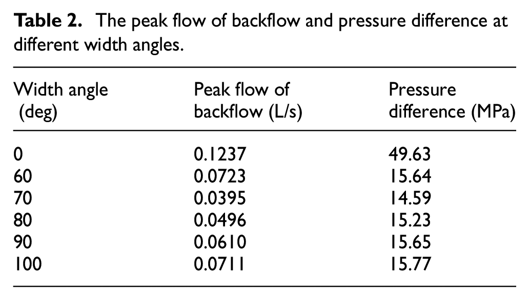
The peak flow of backflow and the pressure difference between intake and discharge oil chambers at different width angles are shown in Table 2. When the width angle is 0 deg, it means that no triangular damping grooves are added, and the depth angle is the same; when the width angle is 60 deg, the peak flow of backflow and pressure difference increase compared to 70 deg because fluctuations in outlet flow and chamber pressure.
The peak flow of backflow and pressure difference at different width angles.
The depth angle θ1
As shown in Figure 20, as the depth angle increases, the peak flow of the backflow increases, and the backflow occurs earlier. As shown in Figure 21, as the depth angle increases, the value of chamber pressure overshooting increases.
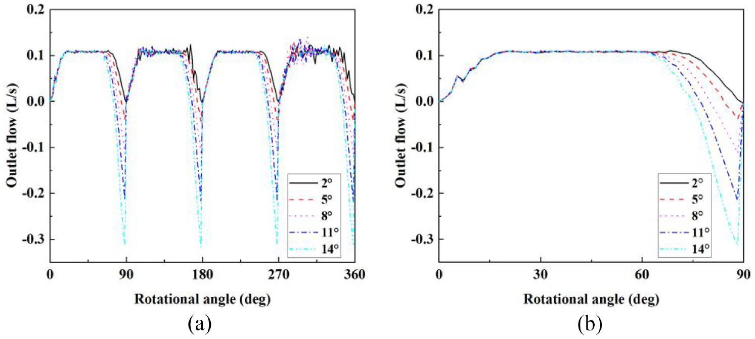
Outlet flow at depth angles of 2, 5, 8, 11, and 14 deg for rotational angle range of: (a) 0–360 deg and (b) 0–90 deg.

Left oil chamber pressure at depth angles of 2, 5, 8, 11, and 14 deg for rotational angle range of: (a) 0–360 deg and (b) 80–100 deg.
Changes in width angle and depth have the same effect on the peak flow of the backflow and abrupt variation in chamber pressure because the flow area of the triangular damping groove increases with either width angle or depth angle increase. The change in depth angle has a more significant effect on the peak flow of the backflow and chamber pressure overshooting because the depth angle has a more significant effect on the flow area than the width angle.
The peak flow of backflow and the pressure difference at different depth angles are shown in Table 3. When the depth angle is 2 deg, the peak flow of backflow and pressure difference decreased by 68.07% and 70.60%, compared to the depth angle is 0 deg.
Peak flow of backflow and pressure difference at different depth angles.

Cloud analysis
Figure 22 shows the pressure cloud and streamline diagrams of the 2D piston electro-hydraulic pump without the triangular damping groove model on Section I. The location of Section I is shown in Figure 23(a). As shown in Figure 22, the oil outlet flow channel exhibits vortex formation, indicating a suboptimal flow state. When the rotational angle is 90 deg, significant pressure pulsation occurs in the distribution groove K, with the maximum pressure exceeding the load pressure by 12 MPa, leading to pronounced pressure overshooting.
The pressure cloud and streamline for without the triangular damping groove model on Section I at various rotational angles: (a) 88 deg, (b) 90 deg, and (c) 92 deg.
Figure 24 shows the pressure cloud and streamline diagrams of the 2D piston electro-hydraulic pump model on Section I. As shown in Figure 24(a), the distribution area between the distribution groove K and the distribution window D is large, while the flow area between the distribution groove M and the triangular damping groove is small; thus, most of the oil in the discharge chamber flows out through the distribution groove K and the oil outlet flow channel, and a small portion of the oil flows into the distribution groove M through the triangular damping groove. As shown in Figure 24(b), with the rotation of the 2D piston, the distribution area decreases while the flow area increases; thus, part of the oil in the oil outlet flow channel flows into the distribution groove M, and backflow occurs. As shown in Figure 24(c), the distribution area is minimized, and the flow area is maximized; thus, most of the oil in the oil outlet flow channel flows into the distribution groove M, and the backflow reaches the peak.
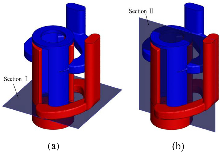
The Sections (a) I and (b) II.

The pressure cloud and streamline for adding the triangular damping groove model on Section I at various rotational angles: (a) 76 deg, (b) 80 deg, and (c) 88 deg.
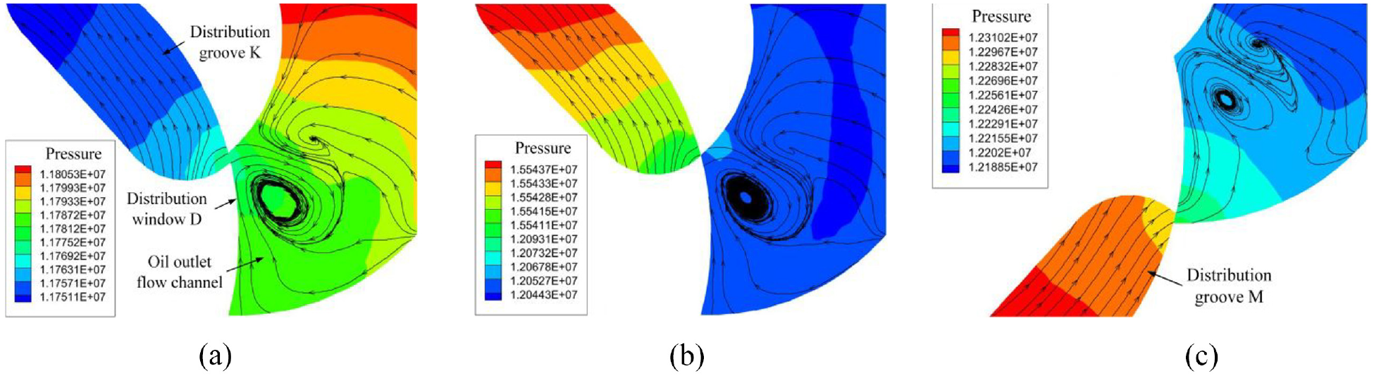
Figure 25 shows the pressure clouds and streamline diagrams of the electro-hydraulic pump model on Sections I and II at different depth angles when backflow begins. The backflow is manifested when the flow area of the triangular damping groove reaches a constant value (critical flow area); the oil pressure in the oil outlet flow channel does not reach the outlet pressure; thus, the oil flows into the low-pressure distribution groove. As the depth angle increases, the critical flow area is reached earlier, and the flow status in the oil outlet flow channel is improved. When the backflow occurs, the oil cannot flow out through the outlet; thus, some oil flows into the low-pressure distribution groove, and the other part can only form vortices in the oil outlet flow channel. As the depth angle increases, more oil flows into the low-pressure distribution groove, and less oil forms vortices.

The pressure cloud and streamline on Sections I and II at various depth angles: (a) 2 deg, (b) 5 deg, (c) 8 deg, (d) 11 deg, and (e) 14 deg.
Conclusion
In this paper, a 2D piston electro-hydraulic pump is proposed, and the contact normal stress in the space cam mechanism is researched by theoretical analysis. The relationship between the chamber pressure overshooting due to the switching of the chamber conditions and the backflow and distribution area is analyzed. A fluid-structure interaction model is established to discuss the chamber pressure overshooting and backflow from the perspectives of width and depth angles and compared to the theoretical analysis. Based on the simulation results, the following conclusions can be obtained:
Firstly, the theoretical analysis is consistent with the fluid-structure interaction results, and adding triangular damping grooves can suppress the backflow and the chamber pressure overshooting.
Secondly, with the increase in the width angle and depth angle, the peak flow of the backflow and the chamber pressure overshooting increase. The increase in depth angle has a more significant effect on the flow characteristics, which requires further discussion. With the increase in the depth angle, the oil flow status in the oil outlet flow channel improves, and the vortices decrease at the moment of chamber condition switching.
Thirdly, when the width angle is 70 deg and the depth angle is 2 deg, the peak flow of the backflow is 0.0040 L/s, and the pressure difference between chambers is 12.80 MPa, which are reduced by 68.07% and 70.60%, compared with the initial model.
Further research on the distribution structure of the 2D piston electro-hydraulic pump will focus on cavitation characteristics and magnetic-fluid interaction. The effect of adding triangular damping grooves on cavitation needs to be further investigated, especially at high rotational speed. In this paper, the motor part is not discussed; thus, the effect of the motor part should be considered in subsequent studies.
Footnotes
Handling Editor: Aarthy Esakkiappan
Declaration of conflicting interests
The author(s) declared no potential conflicts of interest with respect to the research, authorship, and/or publication of this article.
Funding
The author(s) disclosed receipt of the following financial support for the research, authorship, and/or publication of this article: This work is supported by the Zhejiang Provincial Natural Science Foundation Project (No. LGG22E050032).