
Abstract
In this paper, a hybrid fault-tolerant control strategy is putted forward to improve the stability of the four-wheel independent drive (4WID) electric vehicle with motor failures. To improve the handling performance of the vehicle with in-wheel motor failures, the faults of in-wheel motors are analyzed and modeled. Then, a model reference adaptive fault observer was designed to observe the faults in real-time. Based on the observation results, there are designed a model predictive control (MPC) based high-performance active fault-tolerant control (AFTC) strategy and a sliding mode control based high-robust passive fault-tolerant control (PFTC) strategy. However, the fault observation results may not always be accurately. For this circumstance, a hybrid fault-tolerant control strategy was designed to make the control method find a balance between optimality and robustness. Finally, a series of simulations are conducted on a hardware-in-loop (HIL) real-time simulator, the simulation results show that the control strategy designed in this paper is effectiveness.
Keywords
Introduction
Compared with the traditional vehicle, a four-wheel independent drive (4WID) electric vehicle’s driving system is very efficient, its torque output response is much quicker and precise, and every wheel can be controlled independently. These characteristics make it possible to apply advanced control theory to vehicles, which enhances handling performance. 1 4WID vehicles have four in-wheel motors, and their electric systems are quite complex. There are some evidences that 4WID vehicles have a higher failure rate than traditional vehicles. 2 Classifying the factors that cause failures, they can be divided into four types3,4: (1) Drive motor failure: the fault is mainly demagnetization caused by high temperature after high load, under these circumstances, the motor would no longer provide the torque we desired, resulting in a change in the state of the vehicle. (2) Controller and sensor failure: if the internal IGBT components of the controller are malfunctioning, the connectors are in poor contact, or the sensors cannot return the correct value. The output current and voltage of the controller would drop, also the output current waveform may deviate, these would lead to a deviation between the actual output and the desired output. (3) Communication failure: the communication between Micro Control Units (MCUs) mainly relies on the CAN networks, the delay and frame loss of the network affect the coordinated operation between the MCUs, the output of the motor may deviate. Generally, a driving wheel fails (scenarios are shown in Figure 1(a)), which means that at least one in-wheel motor cannot achieve the desired torque, the vehicle handling performance becomes unpredictable and unstable, and the yaw stability of the vehicle may change. 5 As shown in Figure 1(b), the malfunctioning vehicle cannot follow the reference path well with no additional adaptive fault-tolerant strategy. However, it is a 4WID electric vehicle, if one or two wheels (not the same side) fail, the faulty wheel can still provide partial driving forces, the faulty vehicle can still maintain its handling performance. 6

Malfunction analysis: (a) fault tree and (b) the impact of the failure on path following.
Fault-tolerant control (FTC) strategies have been widely used on spacecraft. FTC could improve the performance of malfunctioning systems. At present, fault-tolerant strategies can be divided into two categories: passive fault-tolerant control (PFTC) strategies and active fault-tolerant control (AFTC) strategies.
7
The essence of PFTCs is to enhance the robustness of the system and make the system insensitive to external disturbances. When the vehicle drive system malfunctions, the value of the vehicle’s state response will deviate from the predicted value calculated by the vehicle controller
In order to improve the handling performance of a vehicle with driving system malfunctions, and to overcome the limitations of traditional FTCs, a hybrid fault-tolerant control strategy combined with both PFTC and AFTC was designed. A seven-degree of freedom (7-DOF) vehicle model was established as a reference model to describe the driving system failure, and an adaptive model reference observer was designed to estimate the malfunctions in real-time. A hierarchical FTC strategy was designed, that contains two parts: (1) a model predictive control (MPC) based AFTC and (2) a sliding-mode based PFTC. This hybrid FTC strategy works in AFTC mode if the fault observer is working properly, otherwise, the FTC mode would be switched to PFTC mode automatically.
The rest of this paper is structured as follows. In section II, a 7DOF vehicle model was established, the failures of in-wheel motors were analyzed and modeled, and an adaptive fault observer was designed. In section III, both PFTC and AFTC strategies were designed, and a hybrid FTC strategy was designed. Simulations and hardware-in-loop (HIL) experiments were applied in section IV, followed by concluding remarks in section V.
Fault modeling and analysis
In this chapter, a seven degree of freedom vehicle model with in-wheel motor failures was established. Based on this model, the in-wheel motor output responses and the vehicle dynamic responses can be calculated. Then, compared the model responses with the real vehicle responses, the in-wheel motor fault factors can be estimated.
Vehicle modeling
The 7-DOF vehicle model that contains the longitudinal movement, the lateral movement, the yaw movement, and the rotation of four wheels was established in this chapter. The model has a failure factor that represents the failure, so the model can reflect the vehicle dynamics response under the motor failure situation.
As shown in Figure 2, combined with a Pacejka tire model, 21 a 7-DOF vehicle model 22 can be formulated:


Vehicle model.
The rotation dynamics of each wheel can be calculated by


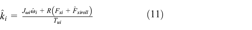
The most common failure of in-wheel motors is magnetic degradation caused by over temperature, which reduces the output torque, and may cause some torque offset. 5 This failure of each wheel can be represented by

However, the most common failures are a reduction in output caused by demagnetization, rather than an offset. 5 Equation (6) can be simplified, the relationship between the desired output and the real output can be simplified:

Thus,

A Simulink/Carsim co-simulation with sinewave steer input was conducted, the results are shown in Figure 3.

Model verification: (a) yaw rate and (b) slip angle.
Compared the response of the 7-DOF vehicle model with the Carsim vehicle model, the 7-DOF model established could reflect the dynamic response of the vehicle. Although there were some gaps in the yaw rate and the slip angle while the tire forces were saturated, the 7-DOF model could still reflect the dynamic responses of the vehicle. The 7-DOF vehicle model established is effective.
Fault observer modeling
In this chapter, a model reference adaptive observer was established to obtain the failure factors. The reference model the parameters were updated in real time, making the reference model response converge to the actual vehicle response. Then, the fault values can be obtained. For in-wheel motor failure factors, the wheel speed values and the vehicle responses along XYZ axles can be chosen as reference outputs.
Assuming that, all the required vehicle states can be obtained by sensors or Kalman filters, 23 according to equation (9), we have:

Similarly, observations
Thus

Then

where
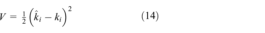
If a Lyapunov function is chosen as
Then we can derive the equation with respect to time t:

A Lyapunov control law can be chosen as

Obviously, if
Since the disturbances and the measurement errors cannot be ignored, and these disturbances would affect the stability and accuracy of the observer, the credibility of fault observation results needs to be evaluated. Assuming that, the value of

where

Combined with equations (10) and (17):

If

If


According to equations (18) and (22), the following conclusions can be obtained: (1) If
Controller design
In this section, a hybrid fault-tolerant control (FTC) strategy was designed, and the system structure is shown in Figure 4. After the fault information was obtained by the observer, the faults were assessed by a strategy selector, and the control method (AFTC or PFTC) with better performance would be activated to take over control.

Hybrid FTC system.
AFTC strategy
In this chapter, a model predictive control (MPC) 24 strategy based upper layer yaw stability controller and a PID based longitudinal motion controller were established. Additionally, a tire force distributor with multiple constraints was also established. These two strategies constitute the AFTC strategy. By adjusting the control system parameters in real time and modifying the outputs to cover the faults, the stability of a vehicle with motor failures can be improved.
Motion control (upper layer)
The longitudinal driving force deviation caused by faults can be corrected by a PID controller. The value of the throttle can be represented by

For lateral control, an MPC based strategy was designed. This strategy is highly adaptable and easily adjust its structure. Since the calculation time for each step is very small, the vehicle status would not change significantly, the value of tire forces and other vehicle parameters can be considered as constants. The vehicle model can be simplified as a two-degree of freedom (2-DOF) bicycle model.
25
To calculate the required wheel torque outputs, the reference vehicle response

Converting equation (24) to a discrete form:

where
Assuming that, at time

where
The target states matrix can be represented by

The optimization function can be defined as

By optimizing the function
Wheel torque distribution (lower layer)
A lower-level torque distributor distributes the additional yaw movement
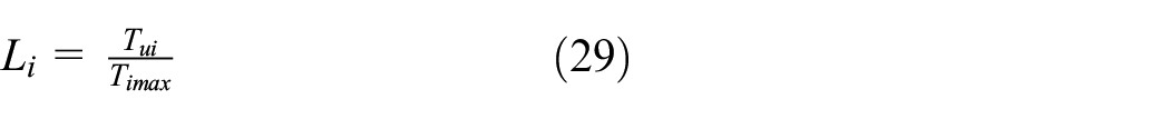


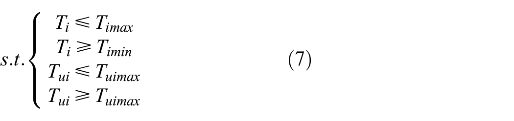
Since the torque of each wheel has an upper limit, the additional yaw movement and the longitudinal driving forces must be constrained. The optimization function and its constraints can be defined by

By minimizing equation (32), the final output value
PFTC strategy
In this chapter, a PFTC strategy was, which was like the AFTC strategy established in the previous section, but a PFTC strategy uses a sliding mode control strategy rather than an MPC method, which is much more robust and much more adaptive. When the observation results are not accurate, this PFTC strategy should still maintain vehicle stability. The main goal of a PFTC strategy is to minimize the yaw rate error and the slip angle error. It can be divided into three parts: yaw rate control, slip angle control, and synergetic control.
Yaw rate control
The yaw rate error and its differential can be defined by


Then, the sliding mode surface of yaw rate control can be defined as

where
where

Slip angle control
Above all, the sliding mode surface of the slip angle control can be defined as
where
where

Synergetic control
During sharp turning, there will be a slip angle at the vehicle mass center, if the additional yaw moment equals to zero. Theoretically, the slip angle can be calculated by equation (24). Usually, the vehicle steering characteristic is under steer, which means in some saturations (sharp turn, etc.) the yaw rate does not increase linearly according to the increase of the front wheel steer angle, 26 at this time, the slip angle of the vehicle will get larger. To maintain the under steer or the neutral steering characteristics, the slop angle value should be emphasized for control. Otherwise, the tire force saturation is not high, the vehicle steering characteristics effect little on the slip angle value, the slip angle changes linearly according to the value calculated by equation (24). To obtain a better control effect, the yaw rate should be chosen as the main control reference. The final external yaw movement can be calculated by

Convergence analysis
To guarantee the robustness of the PFTC control method, its convergence must be analyzed. For example, the convergence of the yaw rate control was analyzed, a Lyapunov function can be defined as


Combined with equation (37):

Assuming that, the malfunctioning wheel would no longer provide any torque (extreme condition), the FTC system should be robust enough to maintain vehicle stable. The disturbance of the yaw movement under extreme conditions can be calculated by

It is obvious that if
Hybrid FTC strategy
In the previous sections, an AFTC strategy and a PFTC strategy were established. PFTCs are robust and adaptive, they are effective regardless of whether the fault factor is precise or not. AFTCs need accurate fault observation results, incorrect fault estimation results would lead to unpredictable risks, which also means that the vehicle yaw stability drops. For this reason, the advantages of both AFTC and PFTC strategies should be exploited, their disadvantages need to be avoided.
After the fault factors were observed and be evaluated. Hybrid FTC strategies are effective. However, there are two situations: Situation 1, the fault estimation result is accurate, the AFTC strategy should be activated. Situation 2, the fault estimation result is not accurate, the PFTC strategy should be activated. However, to avoid the risks caused by the control output fluctuating, the switching process (AFTC to PFTC, or PFTC to AFTC) should be optimized, so that a delay link of mode switching is added to the control flow.
The hybrid FTC system control flow is shown in Figure 5. Assuming that the observation starts at the movement

The control flow of a hybrid FTC system.
Simulation and results
To evaluate the effectiveness of the proposed FTC strategies, simulations on a hardware-in-loop simulator shown in Figure 6 were conducted (the main simulation parameters are shown in Table 1). A Carsim vehicle model ran in a NI real-time desktop computer, the FTC strategies ran in a raspberry PI 3b based rapid controller, the faults were injected by a signal generator. Four simulation scenarios with reference to ISO 7401-2011 standard were conducted: a fault observation simulation, an AFTC simulation, a PFTC simulation and a hybrid FTC simulation. Some of the simulation results were compared with a traditional MPC strategy. 27

Hardware-in-loop simulator: (a) real-time desktop hardware-in-loop simulator and (b) simulator system structure.
Simulation information.

Fault observation simulation
In this simulation, the observer and the AFTC strategy were tested in a straight lane accelerating scenario. A road with
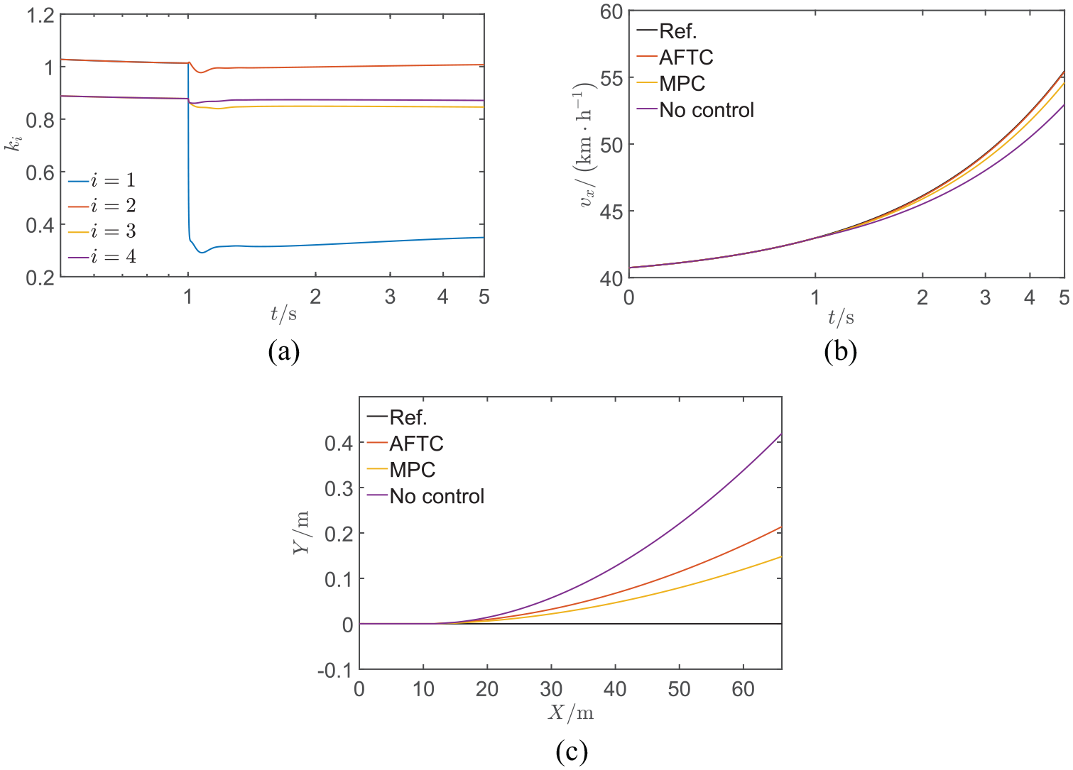
Simulation results of linear acceleration: (a) fault observation results, (b) longitudinal velocity, and (c) tracks.
Figure 7(a) shows that the fault observer could identify the faults in real-time. In the later part of the simulation, the fault observation result error was slightly larger which was caused by the model mismatch and the instantaneous changes of the vehicle state (tire forces, suspension bounces). However, since the FTC strategies were robust, this error could be tolerated. The curves of vehicle speeds at a given throttle were shown in Figure 7(b), the vehicle with AFTC had better acceleration capabilities. In Figure 7(c), the vehicle with a hybrid AFTC controller had a better acceleration performance, because the fault factors were observed, and the driving forces were reallocated. The control strategy was robust enough to tolerate the observation error.
AFTC and PFTC simulation
In this simulation, the effectiveness of both AFTC and PFTC was tested. A road with

Simulation results of sinewave steer input: (a) front wheel steering angle, (b) additional yaw movement, and (c) vehicle status response.
In Figure 8(a) and (b), to make the vehicle states converge to the reference states, an additional front wheel steering angle and an additional yaw movement were applied to the vehicle. In Figure 8(c), both AFTC and PFTC were effective, and due to the additional front wheel steering angle, the AFTC strategy was efficient.
Hybrid FTC simulation
In this simulation, a double lane change (DLC) test scenario was conducted. A multipoint preview driver model was applied to a vehicle that ran at 120 km/h, and a malfunction (

Simulation results of DLC: (a) fault observation results before evaluated, (b) fault observation results (after evaluated), (c) tracks, (d) vehicle status response, (e) front wheel steering angle of hybrid FTC, and (f) additional yaw movement.
As shown in Figure 9(a) and (b), at time
Conclusion
In this paper, a hybrid fault-tolerant control strategy was designed to improve the handling performance and the yaw stability of a vehicle with in-wheel motor failures. (1) A 7-DOF vehicle model-based model reference adaptive fault observer was established to obtain the fault factors in real-time. The accuracy of the observation results was also discussed, and a method to identify whether the observation results were reliable or not was designed. (2) The observation results may not be accurate, different control strategies should be selected for accuracy and inaccuracy. A hybrid FTC strategy was designed. If the faults observation results were accurate, the AFTC strategy would be activated, otherwise the PFTC strategy would be activated. Simulation results showed the strategies were efficient. They had enough ability to maintain the performance of a vehicle with in-wheel motor failures.
However, the switch thresholds in the hybrid FTC flow were obtained based on experience and simulation results, they may not be the optimized value. As for the impact of switching time on vehicle performance, or how to obtain the optimized switching logic, these issues will be answered in our future works.
Footnotes
Appendix
Acknowledgements
All the authors would like to thank the editors and the reviewers for their suggestions.
Handling Editor: James Baldwin
Declaration of conflicting interests
The author(s) declared no potential conflicts of interest with respect to the research, authorship, and/or publication of this article.
Funding
The author(s) disclosed receipt of the following financial support for the research, authorship, and/or publication of this article: All the authors would like to thank all editors and reviews who helped us improve this work. And this work was financially supported by “The Fundamental Research Funds for the Central Universities (2020-YB-020),” and “The Fundamental Research Funds for the Central Universities (2020-ZY-120).”