
Abstract
Encoder is essential for speed control and very valuable in condition monitoring for a mine hoist and the failure in sensor measurements can lead to serious accidents. In this paper, a novel encoder fault detection, isolation and tolerant control strategy based on finite time observers and constrained fault-tolerant controller is proposed for a mine hoist. The hybrid nonlinear observers which can converge to the origin in finite time are employed to detect and isolate faulty sensors, a residuals evaluation unit is then used to provide reconstructed signals. The constrained fault tolerant controller is presented to guarantee steady and safe running of the mine hoist when sensor fails. This approach is feasible and practical because it does not require a complicated update process, and the fault tolerance controller also makes the hoist run more reliably. Compared with traditional ways, the proposed method has superior performance and can be more effective, which are verified by experimental results.
Keywords
Introduction
As essential equipment for mineral transportation, mine hoists have extremely high safety requirements and have become a hot study topic for secure operation. 1–3 A mine hoist will face a variety of working situations, such as drum winding excitation, 4 guide rail deformation, 5 and headgear sheave frictional interference. 6 Above status will greatly affect the running performance of mine hoists and reduce the service life of key components.
In this case, various methods for state monitoring and fault diagnosis of mine hoists have been proposed to prevent major accidents. In Ref. 7, a hybrid method based on a filtering algorithm, Hilbert-Huang transform, energy entropy, and support vector machines is proposed to detect hoist spindle device fault. Machine vision–based measurement approach is used to monitor transverse vibrations of moving hoisting vertical ropes in mine hoists. 8 In the literature, 9 a comparative study of three machine learning algorithms is conducted to detect wire rope damage of mine hoist. An approach based on multi-time scale and dynamic time warping has been used to diagnose guide rail faults of mine hoist. 10 Additionally, many researchers have tried to overcome the effects of interference and to avoid failure by improving control methods. In Ref. 11, performance of three different speed controllers in mine hoist are analyzed under sensor faults. A full-order infinite dimensional observer is constructed in Ref. 12 to improve control effect of mining cable elevator with time-varying sensor delays. In the literature, 13 a robust nonlinear adaptive backstepping controller combined with a nonlinear disturbance observer is proposed to accomplish wire rope tension control of mine hoist. A neural-based adaptive control strategy is developed in Ref. 14 to deal with the problem of tension coordination control against actuator faults and disturbances for a mine hoist. Thus, it is very important to consider the response characteristics of the system under various fault conditions and to design corresponding measures to prevent the occurrence of dangerous distresses, in particular, the sensor fault conditions that researchers pay less attention to.
For a long time, fault diagnosis and fault-tolerant control of complex systems under sensor failure conditions have been the focus of scholars. 15 A number of methods to deal with sensor faults have been developed for use in a variety of industrial equipment such as nuclear power plants, 16 unmanned aerial vehicle, 17 and wind turbines. 18 In order to achieve sensor fault-tolerant control, the crucial thing is to detect and isolate the faulty sensors, which is also the central issue of related research. In general, most sensor fault detection and isolation (FDI) strategies can be divided into model-based strategies and data-based strategies. 19 In recent years, data–based fault diagnosis methods have attracted widespread attention due to their versatility and ease of use. However, as they require a lot of normal and faulty running data for training, 20 they are difficult to be applied in industrial practice, while the model-based approaches avoid this defect.
The structure of a model-based sensor fault tolerant strategy can be roughly divided into two parts: (1) the sensor fault detection and isolation stage for outputting the correct sensor signal and (2) the fault tolerant control stage for maintaining the performance of the system. For the first part, among multiple model-based fault diagnosis strategies, observer-based methods have drawn the widespread attention of the scholars. On the basis of having enough observation sensors, not only can the FDI system be able to isolate the sensor failure, it can also estimate the system disturbance, thus is very practical. In recent years, different structures of observers have been designed to improve the effect of sensor fault detection and isolation. A higher order sliding mode observer-based controller is used to maintain good performance of an electric vehicle motor in event of sensor faults. 21 In Ref. 22, an on-line sensor fault diagnostic scheme based on sliding mode observers are proposed for a commercial aircraft engine. An adaptive observer is developed for sensor fault diagnosis and signal reconstruction of an industrial gas turbine. 23 In Ref. 24, three filters including extended Kalman filter, strong tracking filter, and cubature Kalman filter are proposed to design fault observers for an electronically controlled air suspension system under typical sensor faults and noise. In the literature, 25 adaptive extended Kalman filters have been used to detect and isolate sensor faults for a lithium-ion battery pack of electric vehicles. Fault-tolerant control problem for a three-tank system in the presence of possible sensor bias faults and packet dropout phenomenon has been considered in Ref. 26. Moreover, nonlinear observers including unknown input observers, 27,28 proportional integral observers 29 are some other solutions to mention. However, the above fault diagnose method must be redesigned according to the system model and cannot be used directly to the mine hoist system.
For the fault tolerant control stage, according to the extensive research in the past, if the faulty sensor signal is successfully detected and isolated, conventional control methods can be used to achieve fault-tolerant control of the whole system. A PI controller is designed in Ref. 21 to achieve fault tolerant control of an electric vehicle motor based on switching signal. In Ref. 30, an adaptive backstepping–based fault tolerant control system has been developed for a class of nonlinear systems subject to sensor faults and external disturbances. A fuzzy fault tolerant controller has been developed for proton exchange membrane fuel cells in which linear matrix inequalities (LMI) are used to design parameters of the controller. 31 As an important design tool, LMI is widely used in the design of fault-tolerant control systems based on fuzzy models. 32,33 In addition, sliding mode control technique and its improved method has found extensive applications in sensor fault tolerant domain, as presented in Refs. 34 and 35. However, although the stability of the control system during sensor switching process has been thoroughly studied, 36,37 the dynamic characteristics of the system during sensor switching process must also be taken seriously, 38–40 or it may cause high frequency oscillations in the hoist system. 41
Motivated by above analysis, in this paper, we have proposed a novel nonlinear sensor fault detection, isolation and tolerant control strategy for a mine hoist. First, mathematical models of both the driving motor and the mechanical part are given. Second, hybrid observers which can converge in finite time are designed to detect fault sensor. Then, a guaranteed performance fault tolerant controller which can constrain the input change rate of the system is proposed to attenuate the dynamic oscillation during the sensor signal switching process. The main contributions of this research can be summed up as follows: (1) A novel hybrid nonlinear observer-based FDI strategy for mine hoist with speed sensor fault is proposed. Unlike existing observer–based FDI works, the proposed sensor fault observer ensures finite time stability of the observation error for fast signal reconstruction. Further, the proposed strategy is robust to parameter variations and bounded model uncertainties, which vary according to the running conditions. (2) Input amplitude and input rate constraints is considered in the design of fault tolerant controller. Compared with existing design techniques, the proposed controller can well handle the chattering caused by sensor signal switching process, thus reducing system vibration and ensuring system performance. (3) Experimental results are used to demonstrate the effectiveness of the proposed control strategy. Unlike the existing works, this paper proves that proposed method is feasible in the actual industrial environment.
The remainder of this paper is as follows. In Mine Hoist Description, the mechanical structure of the mine hoist is introduced. Modeling the Mine Hoist presents the model of both the system and the fault sensors. Design of Sensor Fault Diagnosis and Fault Tolerant Control System proposes multiple observers to detect and isolate fault sensors; a guaranteed performance fault tolerant controller is subsequently designed to reduce oscillations during sensor switching. The performance of both the FDI unit and the fault tolerant controller is evaluated via experimental research in Experimental Results. At last, Conclusion draws the conclusion of this work.
Mine hoist description
The construction of a single rope winding mine hoisting system is presented in Figure 1. On the whole, the mine hoisting system is made up of a mechanical transmission subsystem and a motor drive subsystem. The mechanical transmission subsystem consists of a wire rope wound around the drum, a headgear sheave placed on the derrick, a conveyance suspended at the end of the rope, and guide rails installed inside the wellbore. The motor drive subsystem consists of an encoder mounted at the end of the spindle, a motor, a drive and a controller. The controller collects the speed signal from the encoder and compares it with the reference signal. After calculation, it outputs a control signal to the driver, and then the motor speed can be controlled. Structure diagram of the mine hoisting system.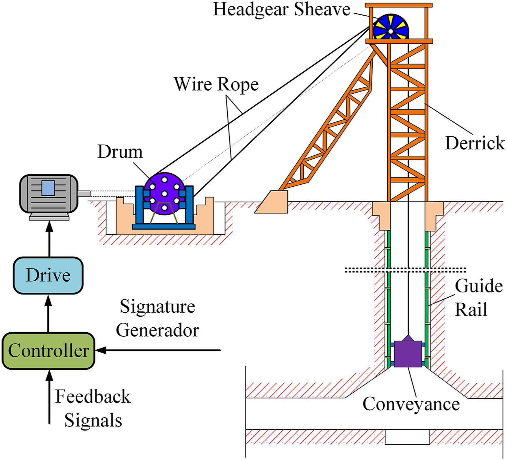
Modeling the mine hoist
In this section, to achieve the design of the fault tolerant controller and related simulation analysis, first of all, the mathematical model of the motor is presented. And then the kinetic equation of the mechanical subsystem is given.
Mathematical model of the motor
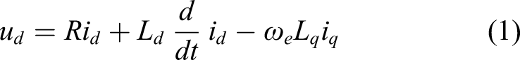
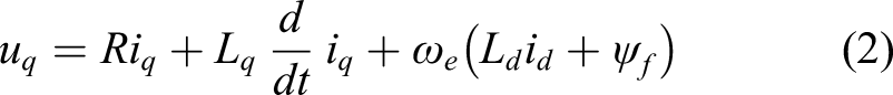
Considering the subsequent experimental condition, it is assumed that the motor selected for the mine hoist is a 4 pole pairs’ permanent magnet synchronous motor, and the mathematical model of the motor in the synchronous rotating coordinate (d-q) can be described by following equations
42
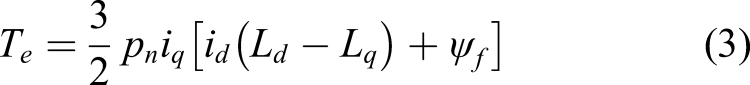
The electromagnetic torque of the motor can be described as
Mathematical model of the mechanical structure
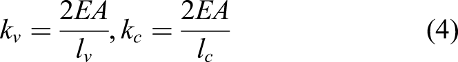
Figure 2 depicts the mechanical structure of the mine hoisting system whose mechanical properties are represented using a lumped parameter model. The drum inertia, headgear sheave inertia, and conveyance are lumped at their corresponding locations. The masses of the wire ropes are lumped at discrete points and then united to the drum, the headgear sheave and the conveyance. The stiffness coefficients of the wire ropes can be given as following Mechanical structure of the mine hoisting system.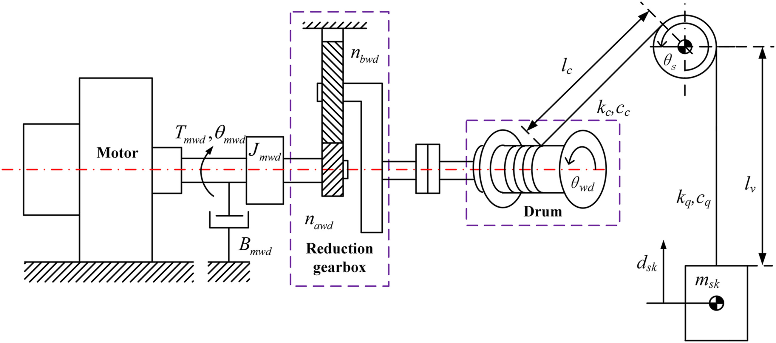
Picking
Mathematical model of the sensor faults
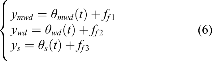
According to Ref. 43, three types of encoder faults for mine hoisting system are the abrupt fault, the intermittent fault and the incipient fault. These types of faults may cause the encoder to stop working or lead to a deviation in the measured value of the sensors. To describe the possible failure of the encoder, in this paper, when the i-th encoder fails, the corresponding measurement signal of the sensor can be written as
Design of sensor fault diagnosis and fault tolerant control system
In this section, to achieve sensor fault detection, isolation, and tolerant control of the mine hoist, as shown in Figure 3, two fault observers are first proposed for detecting and isolating faulty sensors. Specifically, the input of the first observer is the motor speed, and the input of the second observer is the drum velocity. By evaluating the residuals of the two observers, we can detect the fault sensor and reconstruct the feedback signal. A dynamic surface controller is then designed to maintain the performance of the system in the event of sensor faults. Block diagram of proposed strategy.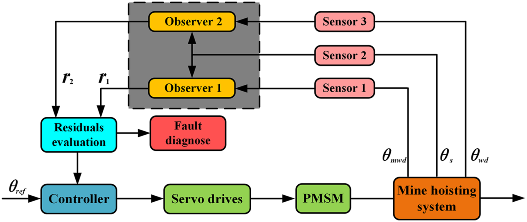
Observer-based sensor diagnosis
According to equations (1)–(6), define state variables of the mine hoist as
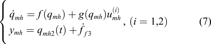
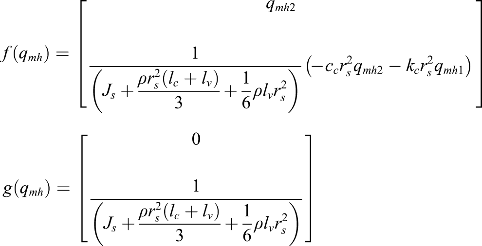
Both The proposed adaptive observer is designed as follows Define the error between the observer output and the measured value as
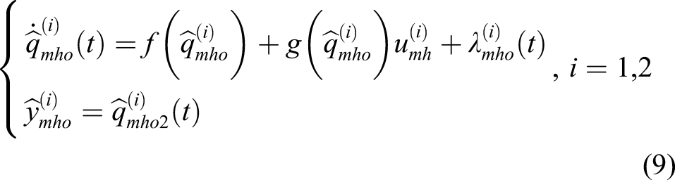
For an actual mine hoist, abrupt sensor failure can be easily identified
44
, considering Let the compensation function of the observers to be defined as
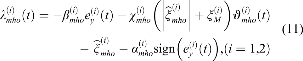
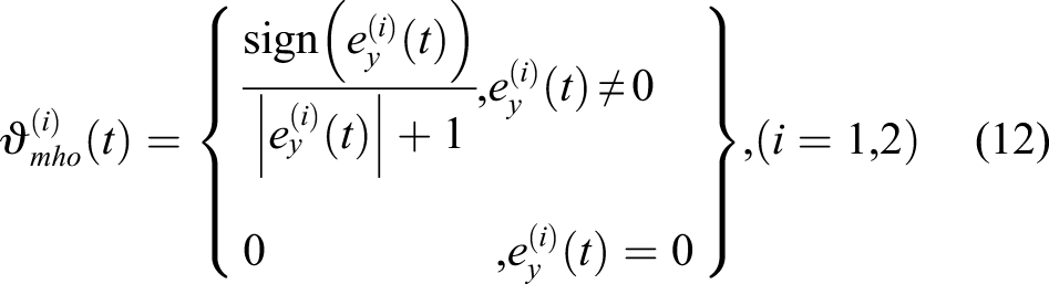
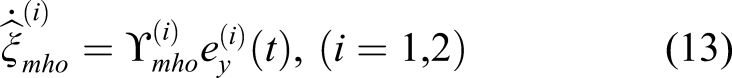
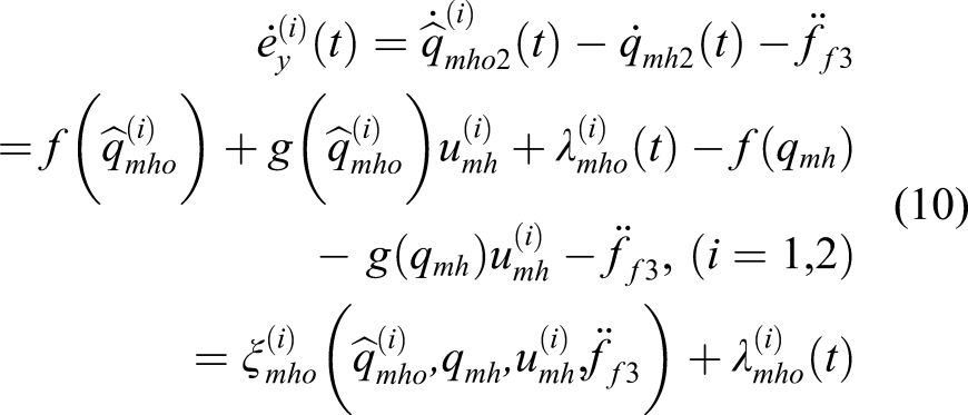
For mine hoist subject to sensor fault (7), develop an observer as (9), if the compensation function (11) is applied, then the output observation error
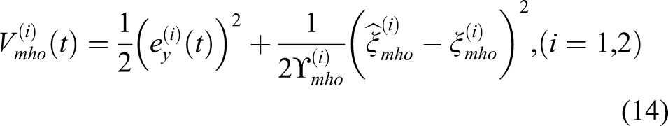
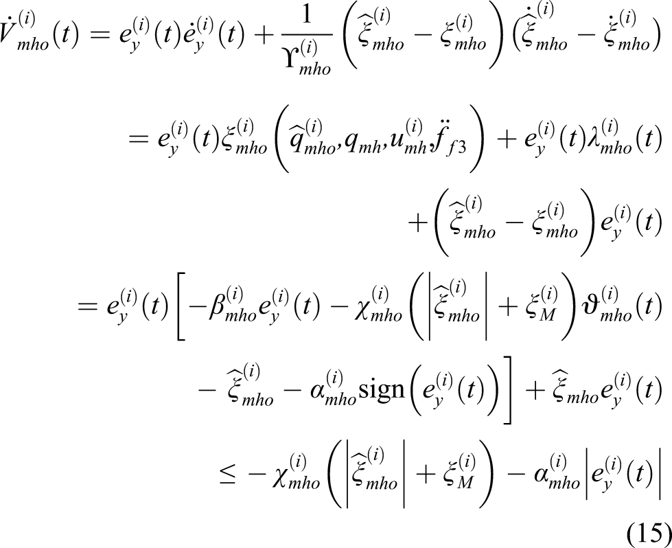
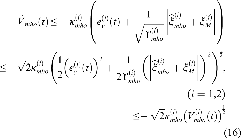
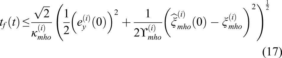
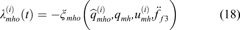
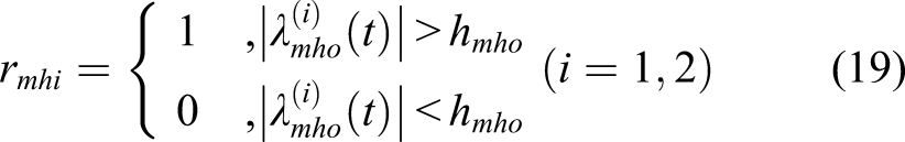
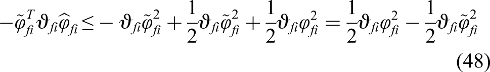
To prove the convergence of the error in finite time, let us choose the following Lyapunov function Using equations (10) and (11), the time derivative of the Thus, we have Solving inequality (16), we can get that In case that the conveyance of the observer is accomplished, the By analyzing the composition of the formula (16), we can find that when the encoder of motor fails, only At the same time, in order to prevent false alarm, we define In the light of above index, a switching strategy is proposed to achieve fault signal isolation and reconstruction. Define the output fault signal as y
fso
and the actual feedback signal as y
fs
. From equations (7), (9) and (10), we can get sensor fault diagnosis and signal reconstruction strategy as shown in the Table 1. Here, the signal switching and replacement method utilizes the redundant relationship between the motor encoder and the drum encoder thus having high efficiency and accuracy. For headgear sheave encoder which does not participate in the closed loop control, accurate sensor fault diagnosis is not performed.
Sensor fault diagnosis and signal reconstruction strategy.
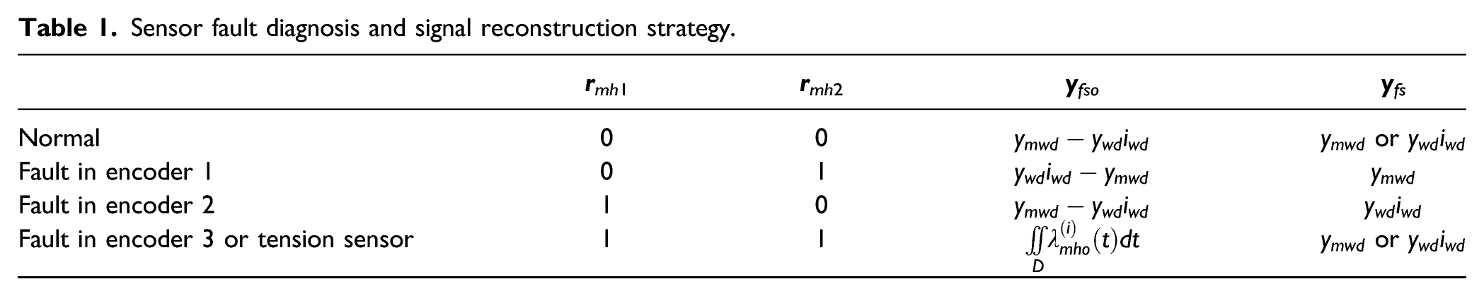
As the low probability of multiple sensors fail at the same time, this paper only considers the case where only one sensor fails during the same time period.
Design of fault tolerant controller
According to the results of the previous section, by comparing the residuals of the observers, on the one hand, the faulty sensor can be effectively isolated, and on the other hand, the signal of the healthy sensor can be fed back to the controller. However, the problem that the hard switching of the feedback signal will cause oscillation of the mechanical structure, especially for hoists with flexible components. To this end, this section designs an input rate limit controller to achieve smooth control of the hoists during signal switching process.
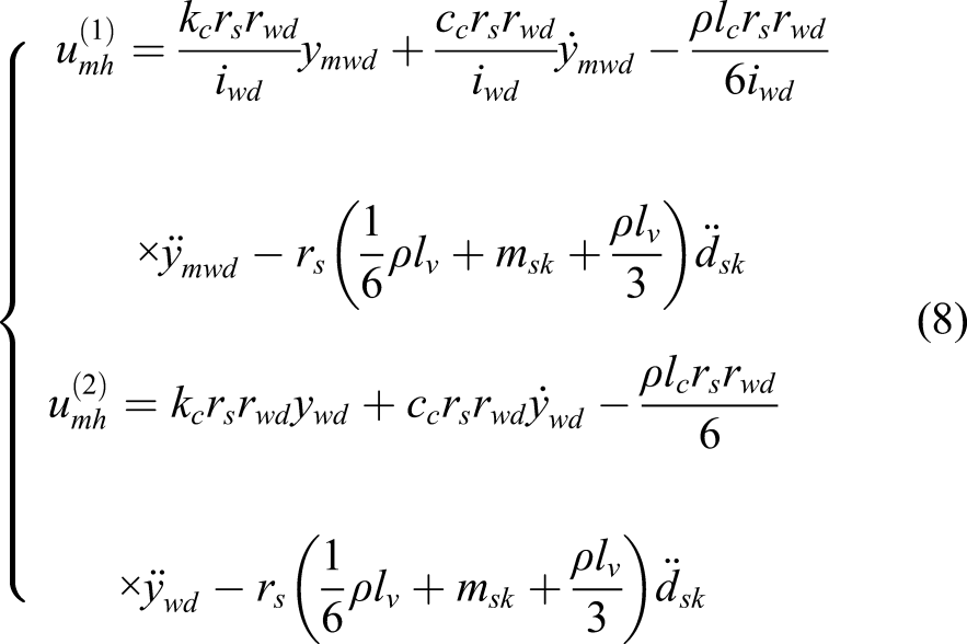
Based on above analysis, from equations (1)–(6), the equation of the simplified driven subsystem can be given as
46
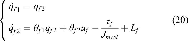
When the sensor fault diagnosis system designed in Observer-based Sensor Diagnosis operates correctly, we can get the correct value of the state variables. According to equation (20), the design procedures of the proposed fault tolerant controller are presented in the following.
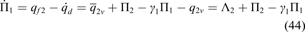
The rotation angle tracking error can be defined as Thence, the time derivative of equation (21) can be formulated as Define Set the low-pass filtered output of 


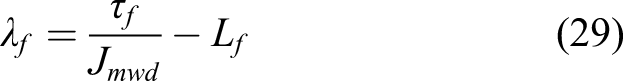
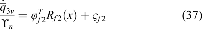
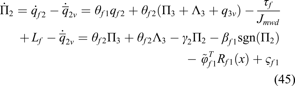
The rotation velocity tracking error is selected as The time derivative of Design Define the actual value of all unknown items as Using universal approximation characteristic of the neural networks, we have Choose the low-pass filtered output of 

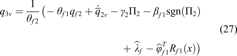


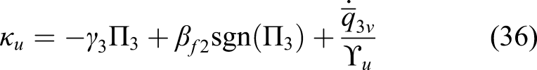
The input tracking error can be selected as The time derivative of To achieve the input change rate limit, Invoke the mean-value theorem,
47
equation (34) can be written as And the control input can be designed In order to facilitate the solution, reuse the universal approximation of the neural network, we can define Subsequently, equation (36) can be rewritten as Since 


Consider the mine hoist driven subsystem (20), apply control law (23), (27) and (36), with low-pass filter (24), (31), and adaptive law (28), (40). Then, all signals in the speed closed loop control subsystem are uniformly ultimately bounded (UUB), and the rotating speed tracking errors converge to a small neighborhood of the origin.
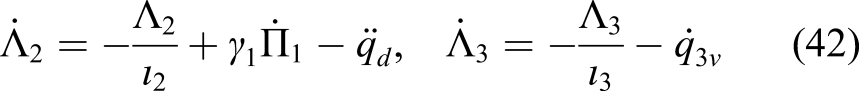
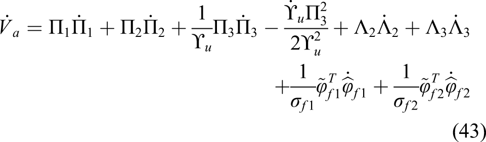
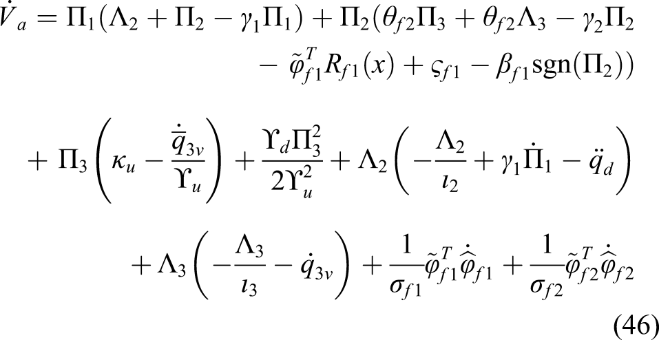
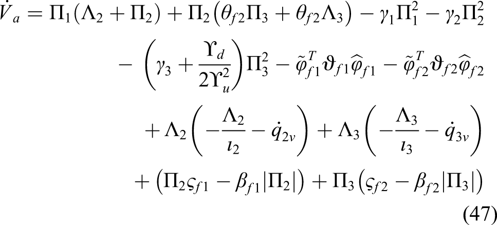
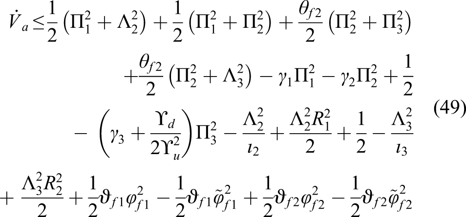
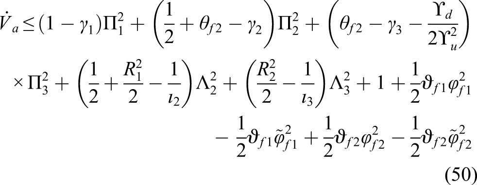
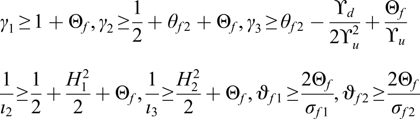
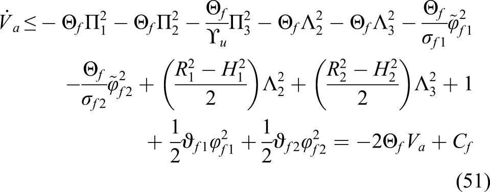
Let the Lyapunov function be defined as follows According to (22) and (31), the differential of filter errors are given as Differentiating From equations (22), (23) and (25),we can get According to equations (26), (27), and (32) we have Using equations ( 42), (44) and (45),we can write equation (43) as Introducing equation (28) and (40), it is obvious that It is clear that Then we further obtain Hence Let us take Therefore And then we can get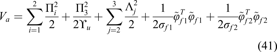
Experimental results
Introduce of experimental condition
To evaluate the practical implementation effect of the proposed strategy, a simulated mine hoist experimental platform has been built as shown in Figure 4. The test bench contains a drum for hoisting purpose and a headgear sheave for changing direction. A conveyance in which the mass can be placed is suspended at the end of the wire rope. The electrical machine driving the drum is a 400 W four pole pair motor which is connected to a planetary gearbox with a reduction ratio of 1:10. Corresponding to the above sensor fault diagnosis method, the first encoder is a motor built-in encoder, the second encoder is connected to the right end of the spindle, and the third encoder is mounted to the side shaft end of the headgear sheave. The three sensors output pulse signals along with the rotation of the motor, and the capture card PCI 6601 which is installed at Advantech target computer accumulates the pulse signals and calculates the rotation angle of the three positions. The fault diagnose and tolerant control strategy is written in the matlab/simulink environment of the host computer and then be downloaded to the target computer for execution. After the board PCI-6024E receives the execution signal, it sends electricity signals to the servo drive and controls the rotation speed of the motor, so that the operation of the experimental platform can be realized. The sampling interval of the control system has been set as 1000 Hz and the main parameters of the experimental platform used for model description are m
sk
=3.57 kg, Mine hoist experimental platform.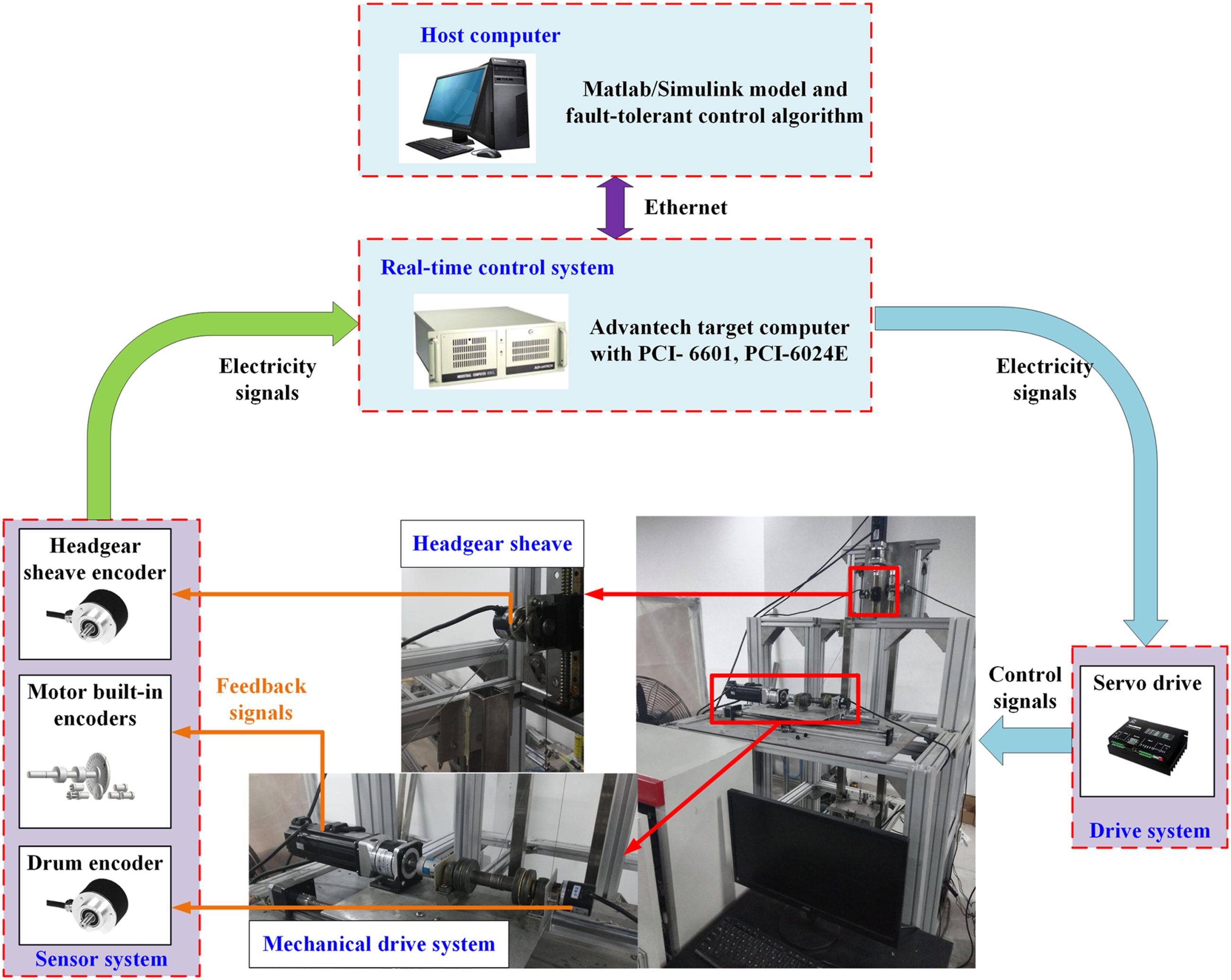
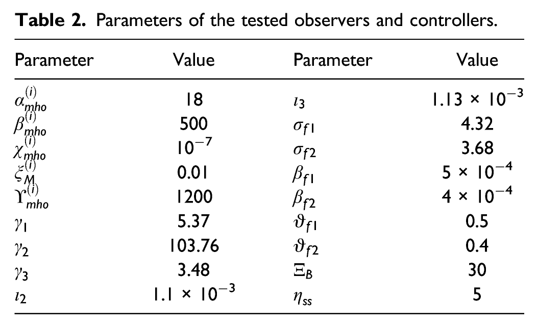
Parameters of the tested observers and controllers.
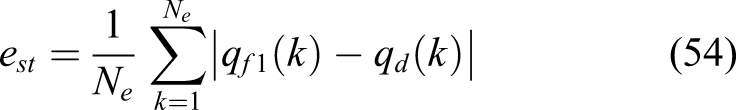
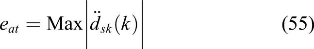
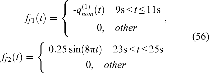
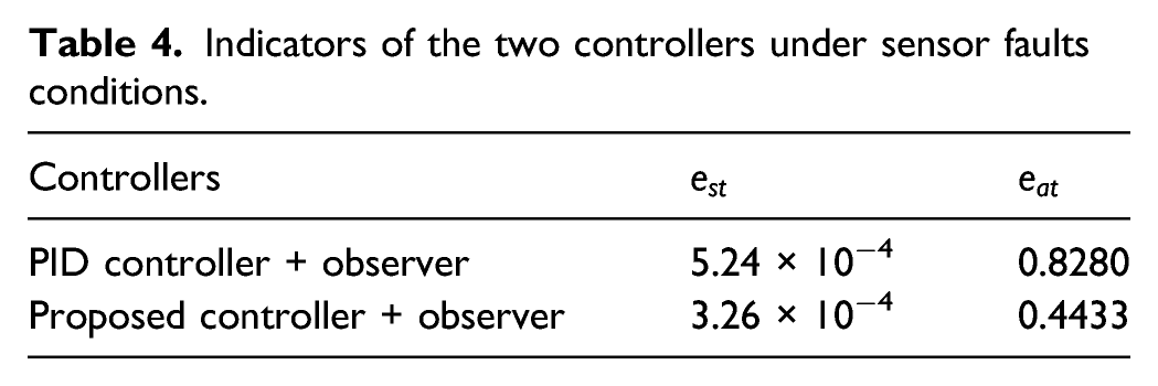
In order to reduce the chattering phenomenon caused by the symbol function In addition, to evaluate the performance of the controllers more accurately, two indicators are proposed for comparison. On the one hand, for accessing the speed tracking effect of the controller, mean absolute error between reference curve and the real speed output of the hoisting process are presented. On the other hand, since acceleration of the conveyance is an important performance of the mine hoist, maximum conveyance vibration is considered as another indicator. The calculation formula for the two indicators are given as follows And two types of encoder faults are considered: encoders have frozen and misaligned faults at different times which are modeled as follows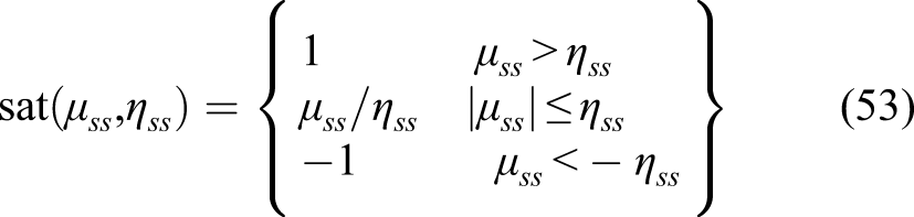
Experimental results
Experimental results under two scenarios are presented in this section to display the applicability of the proposed strategy.
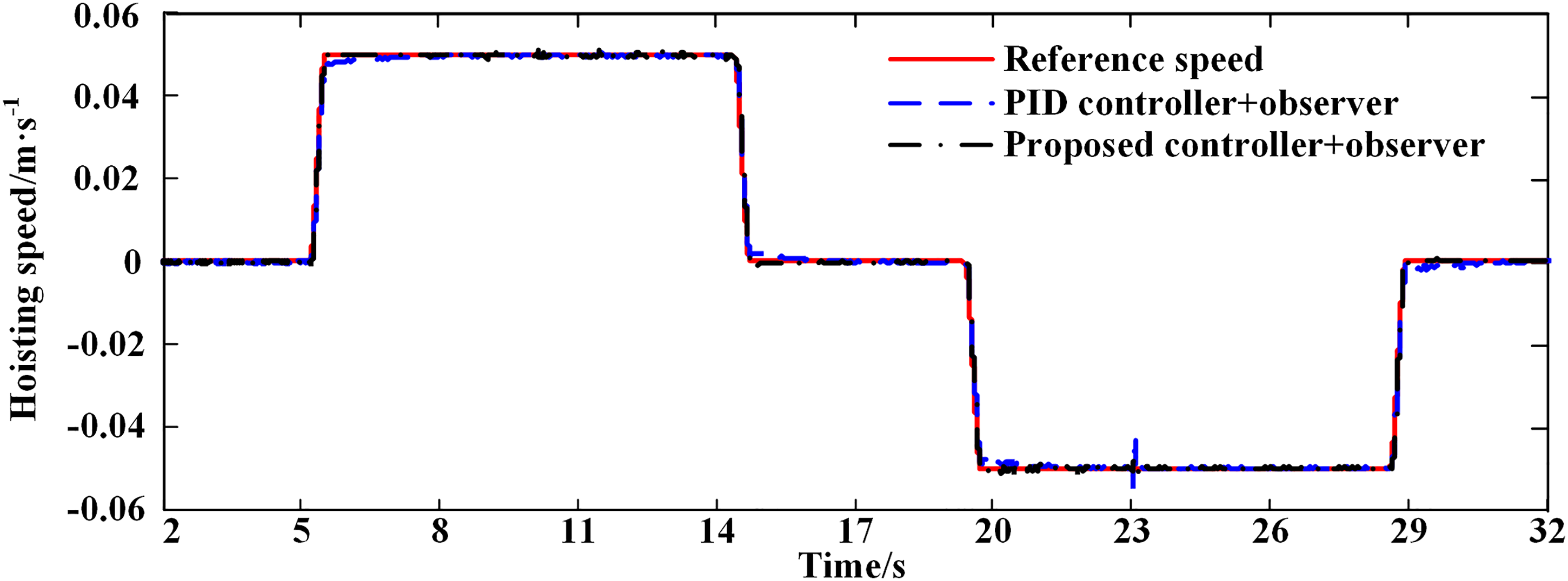
In the first scenario, think over the situation where no sensor failure occurs, the reference motor speed curve and the tracking curve of the two controllers are shown as Figure 5. The running process includes a rising stage and a falling stage, and each stage can be divided into an acceleration operation phase, a constant speed operation phase and a deceleration operation phase. The maximum speed and maximum acceleration of the reference curve are set to 0.05 m/s and 0.2 m/s2 respective. Speed tracking performance with two controllers under no sensor faults conditions (Experimental).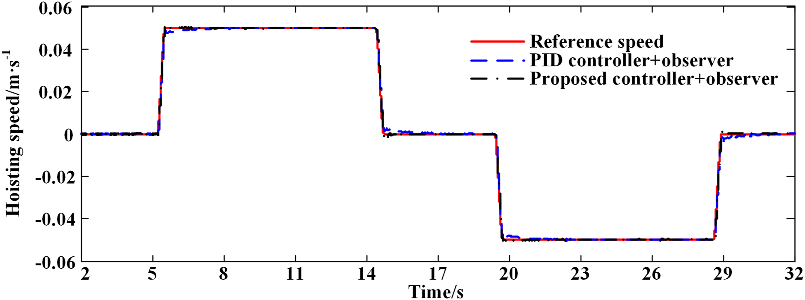
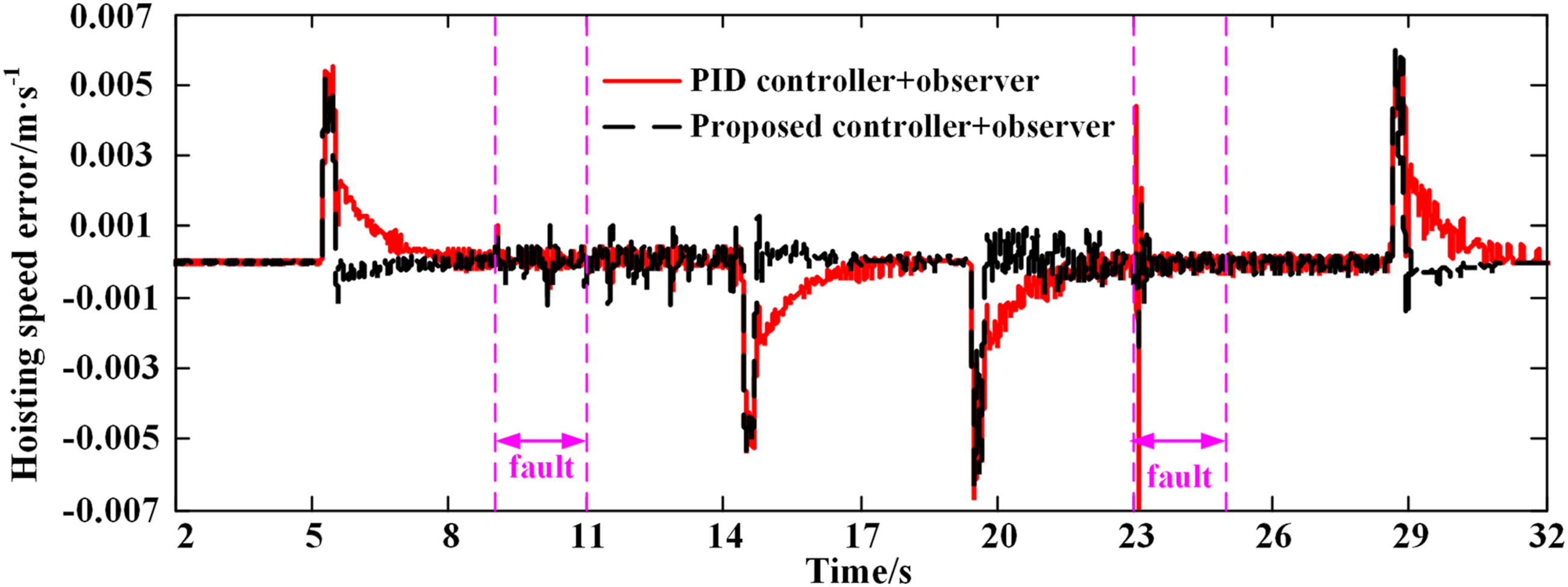
Figure 6 illustrates the speed tracking error with two controllers under no sensor faults conditions. It can be seen that the two controllers have similar speed tracking performance under normal conditions. Speed tracking error with two controllers under no sensor faults conditions (Experimental).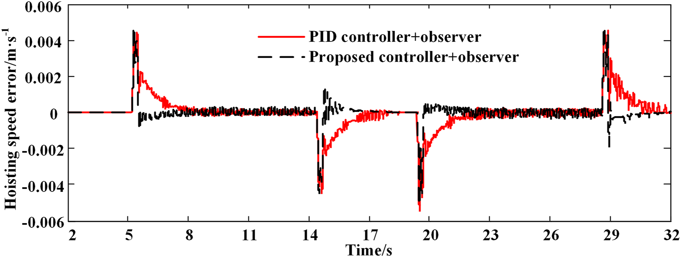
Figure 7 depicts output of fault observers under no sensor faults conditions. It can be observed that both Output of fault observers under no sensor faults conditions (Experimental): (a) 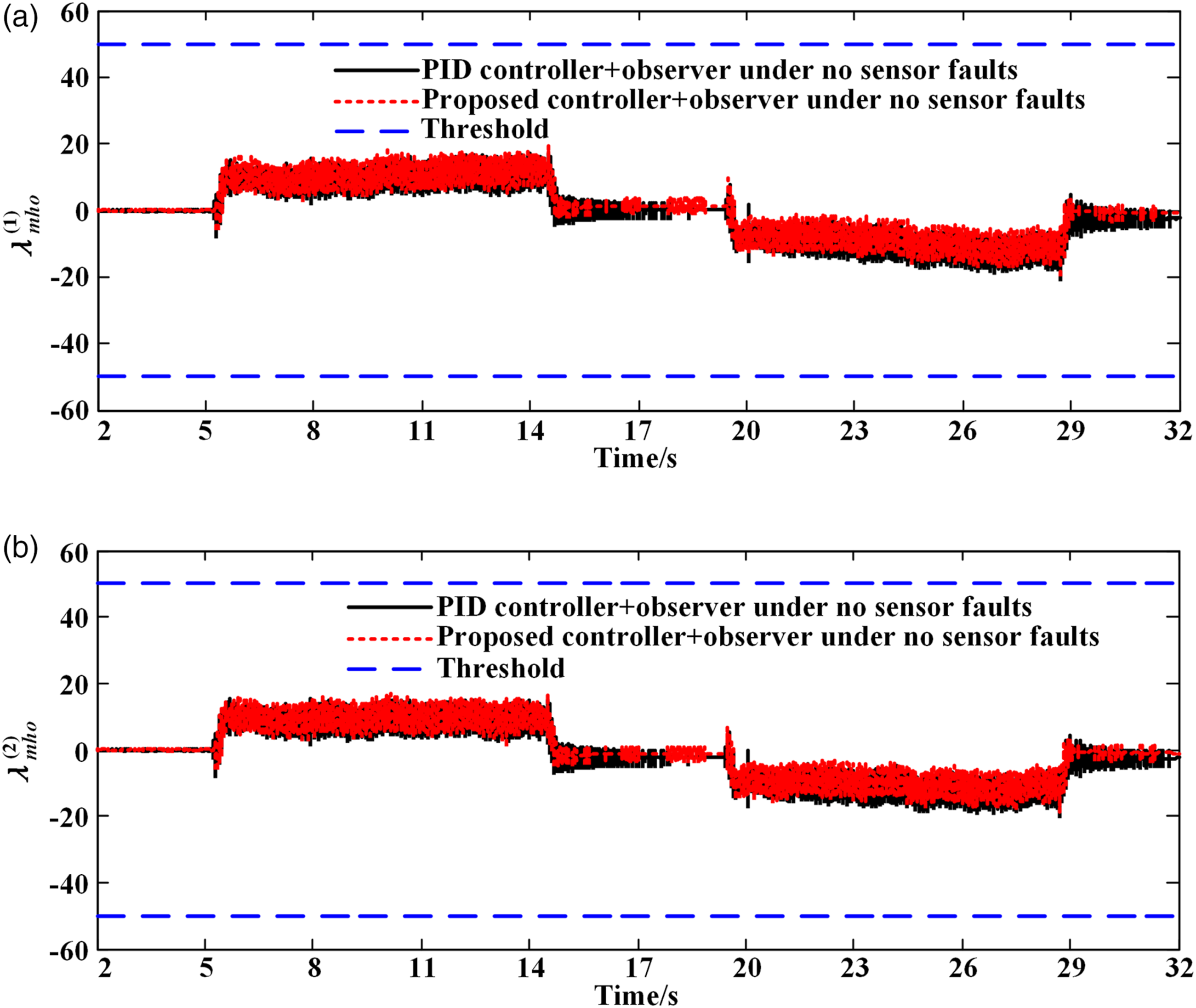
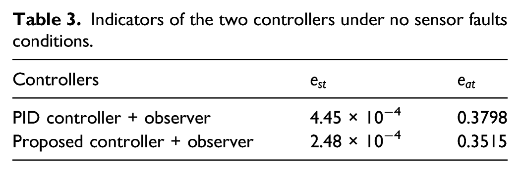
Vibration response of the conveyance with two controllers under no sensor faults conditions are shown in Figure 8. As can be seen, the conveyance moves smoothly under the action of both controllers. Another effective mean for evaluating the performance of the two controllers are the two indicators. Table 3 gives the indicators of the two controllers under no sensor faults conditions during 2 s–32 s. It can be noticed that compared with PID controller, mean absolute speed tracking error is reduced by 44.27% and maximum conveyance vibration is reduced by 7.45% under the action of proposed strategy. Vibration response of the conveyance with two controllers under no sensor faults conditions (Experimental). Indicators of the two controllers under no sensor faults conditions.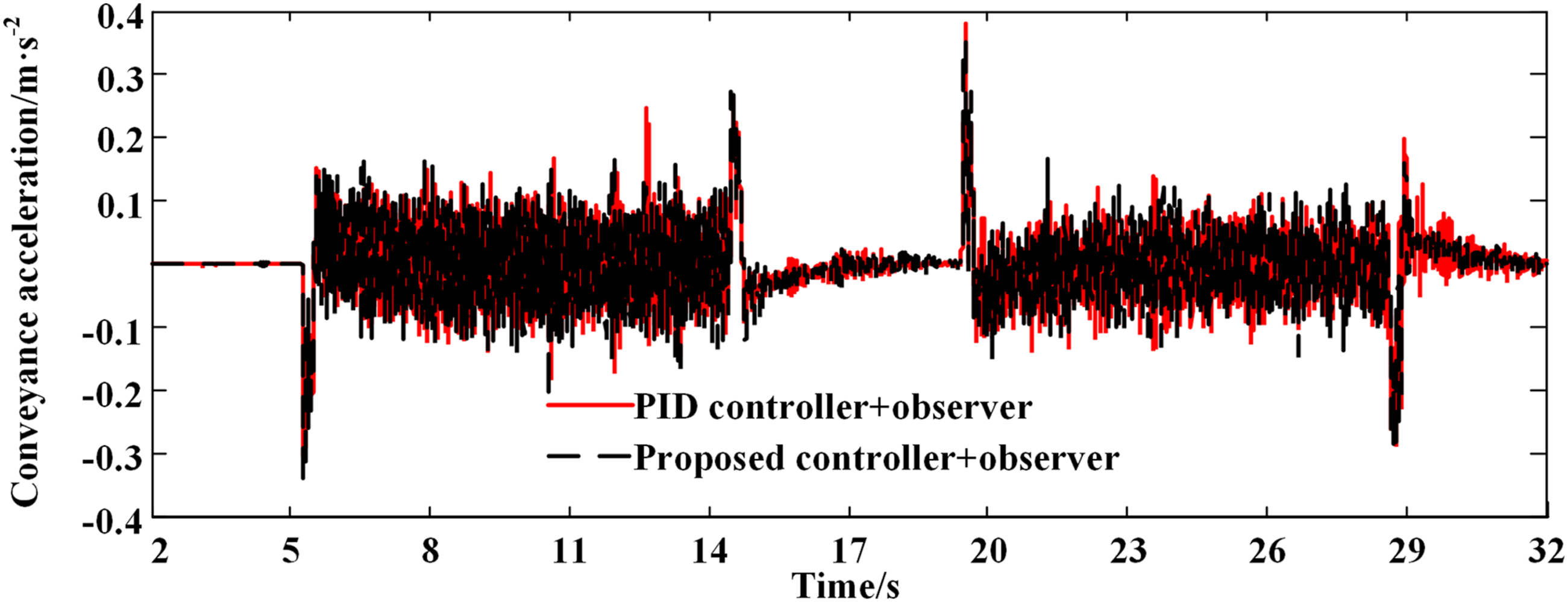
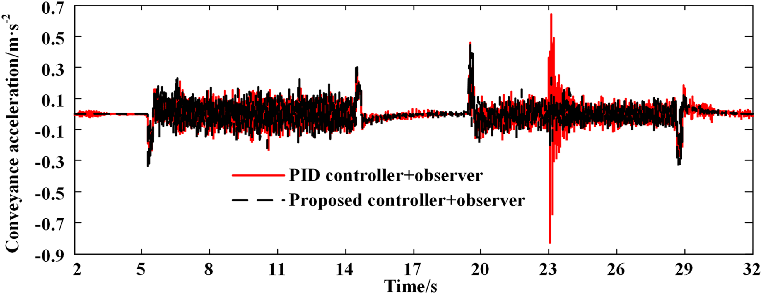
In the second scenario, consider the case of the encoders faults as shown in equation (56). Figure 9 gives output of the two fault observers under sensor faults conditions. It can be noticed that when the motor encoder frozen fault takes place at 9.001 s, the observed Output of fault observers under sensor faults conditions (Experimental): (a) Speed tracking performance with two controllers under sensor faults conditions (Experimental). Speed tracking error with two controllers under sensor faults conditions (Experimental). Vibration response of the conveyance with two controllers under sensor faults conditions (Experimental). Indicators of the two controllers under sensor faults conditions.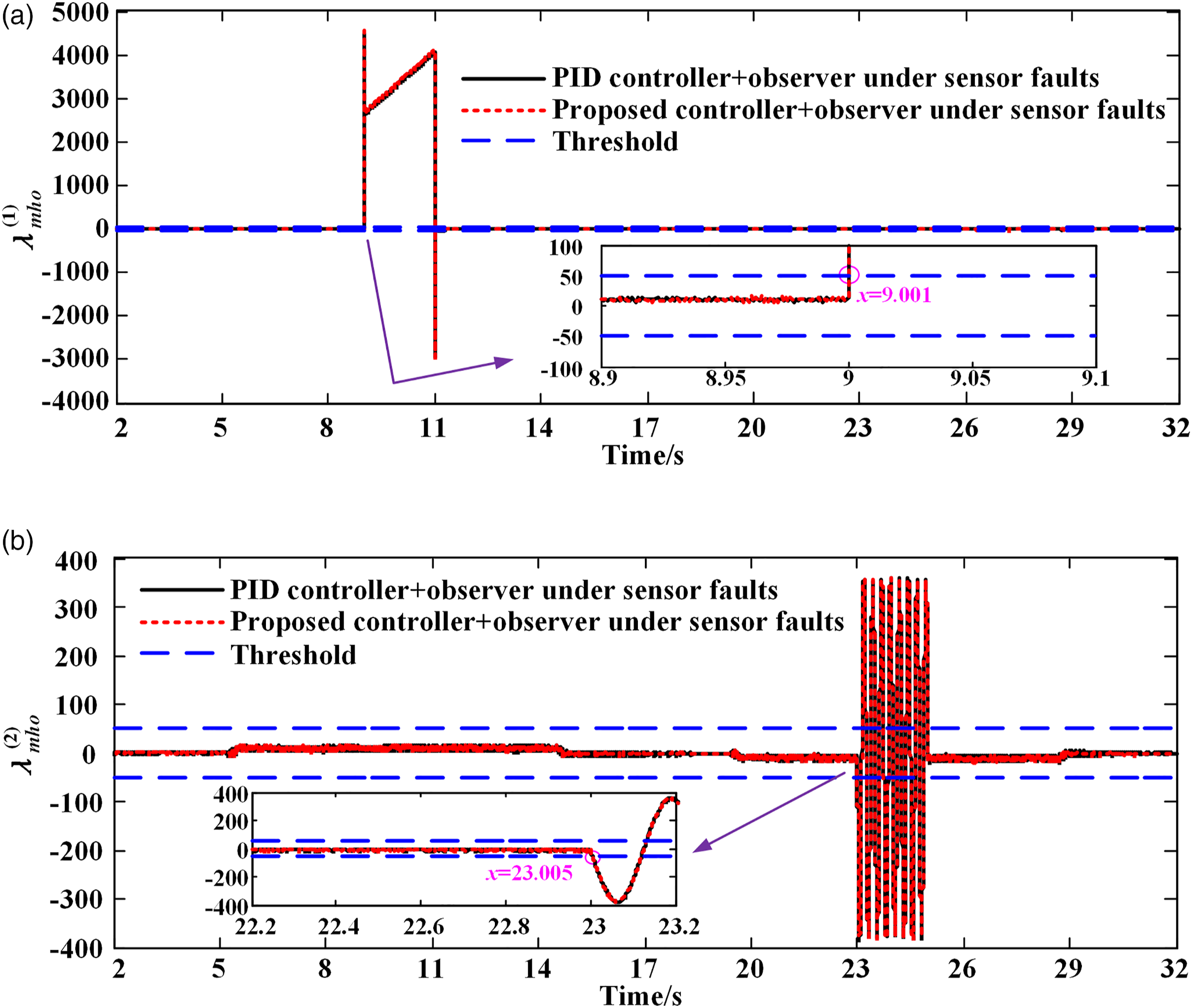
Conclusion
In our article, we proposed a model-based fault detection, isolation and tolerant control strategy for a mine hoist with sensor faults. With nonlinear hybrid observer designed for sensor fault detection, the proposed method is capable of identifying the fault sensor in time and feed backing the reconstructed signal. A dynamic surface controller with input rate constraint was subsequently proposed to achieve smooth operation of the conveyance. The proposed strategy has been tested in a mine hoist experimental platform. The experimental results show that the observer based fault diagnosis scheme can effectively detect and isolate sensor faults. At the same time, compared with slow-changing sensor fault, sudden sensor fault like encoder frozen has smaller impact on the controller, as it can be detected immediately. The feedback signal switching caused by the slow-changing fault will cause the system to oscillate, and the constraint dynamic surface controller can greatly reduce the conveyance oscillation caused by the sensor switching process compared with the conventional PID controller. Extension of the proposed scheme to mine hoist control systems with time delay will be studied in our future work.
Footnotes
Declaration of conflicting interests
The author(s) declared no potential conflicts of interest with respect to the research, authorship, and/or publication of this article.
Funding
The author(s) disclosed receipt of the following financial support for the research, authorship, and/or publication of this article: This research was funded by University-level key projects of Anhui University of science and technology (xjzd2020-14), the Key Projects of Natural Science Research in Anhui Universities (KJ2021A0426), the Program for the University Synergy Innovation Program of Anhui Province (GXXT-2019-029), the Start-up fund for introducing talents scientific research of Anhui University of Science and Technology, Program for Changjiang Scholars and Innovative Research Team in University (IRT_16R68). This work is also supported by the Institute of Energy, Hefei Comprehensive National Science Center under Grant No.21KZS215.
Appendix