
Abstract
Micro-pitting is a common fatigue failure mode of spur gears. To reduce it, this paper proposes a novel tooth tip relief method. Gear meshing simulation is firstly performed considering the actual contact path, showing that there are four Hertz contact stress peaks in the transition areas of the tooth flank. Equations are then developed for the novel tooth tip relief method: one focuses on the smooth transition between the involute profile and the tip relief region, the other on the smooth transition between the tip relief region and the tooth tip. The results of curvature radius and Hertz contact stress show that the proposed novel method can effectively reduce the Hertz contact stress peaks, which indicates this tip relief method could benefit for reducing the micro-pitting. Finally, both wear simulations and bench tests are conducted, verifying the effectiveness of the proposed method for reducing the micro-pitting of spur gears.
Introduction
Spur gears are widely used in heavy-load machinery, such as vehicles, railway equipment, ships, and wind turbines. In the meshing process of spur gears, various fatigue modes occur on the tooth surface owing to the complex and harsh working environment. Among them, micro-pitting is a predominant early stage fatigue mode in most engineering applications. Micro-pitting, manifest as matt patches in tooth-flank areas, causes unexpected vibration and noise,1,2 and may propagate into macro-pitting, spall, and even tooth fracture, 3 ultimately leading to the failure of the gears.
Recently, numerous studies on micro-pitting have been carried out, including contact stress, material properties, microstructure, tribological conditions and load, etc. Using a finite element elastic plastic contact model, 4 Wang et al. 5 found that rolling contact fatigue decreases as tensile stress increases. Roy et al. 6 found that greater retention of austenite leads to reduce micro-pitting with the same cycles. In addition, studies on the microstructure of the gear surface position. Tribological 7 and mixed lubrication conditions 8 also play important roles in the initiation and propagation of micro-pitting in the tooth flank. Zhang et al. 9 found that the root of the mean square of the surface10–12 have revealed that the anisotropy and randomness of the crystal plasticity result in variations in the crack initiation roughness significantly influenced the competition between micro-pitting and pitting. In a study by Morales-Espejel et al., 13 the contact sliding speed, pressure, and specific film thickness influenced the final damage level of micro-pitting based on a stable lubrication condition. However, a remarkable study by Li and Kolivand 14 revealed the dynamic relationship between contact stress and lubrication conditions, suggesting a dynamic model for micro-pitting. The effects of micro-scale surface irregularities on micro-pitting were also discussed by Moorthy and Shaw. 15
Many methods to reduce micro-pitting have been proposed, and improvement of surface 16 and tribological 17 qualities are the most widely applied. The hindering of austenite retention in the micro-pitting of carburized steel was investigated by Roy et al. 18 under boundary lubrication conditions. An ultrasonic nanocrystal surface modification technique by Qin et al. 19 can be used to reduce the surface roughness to reduce micro-pitting. Furthermore, surface coatings20–22 have also been proved effective in mitigating micro-pitting. Different lubricant additives 23 added in a base of low viscosity polyalphaolefin also influenced the micro-pitting with different degrees.
Previous studies24–26 have indicated that contact stress contributes to micro-pitting, and that this stress is determined by the instantaneous meshing state of the gear pair. Many papers have also reported that the load distribution 27 was improved by influencing the meshing state through proper tooth tip relief. Although it is not the same as reducing the micro-pitting of the tooth surface directly, using tooth tip relief to influence the meshing state will also affect the contact stress, thereby affecting the micro-pitting. In fact, a proper tooth tip relief is a relatively economical method to prevent micro-pitting in engineering practice. Optimal tooth tip relief 28 results in better lubrication behaviors for reducing micro-pitting of gears, as has been proved by rigorous experiments. Simon 29 presented a linear function for the simultaneous calculation of optimal tooth tip relief and tooth crowning for spur and helical gears, which improved the load and stress distribution considerably. Ni et al.30,31 improved the contact performance by a parabolic tip relief by a numerical design approach based on the gear-manufacturing and meshing theory. The dynamic responses of low contact ratio spur gear by linear and parabolic tip relief 32 have been compared for the minimum dynamic load of gears under different working conditions. The width modification of a spur gear 33 can reduce the micro-pitting by eliminating the Hertz contact stress. Mao 34 considered not only tooth tip relief but also lead crowning in the face-width direction to be highly accurate modification methods for reducing gear surface pitting, but this research lacked bench test verification. Bruyere et al. 35 analyzed the combination of profile relief and lead crowns in narrow-faced helical gears.
Linear tip relief, widely used in engineering applications, is an effective and economical method for reducing micro-pitting, but it leads to an increase in the local Hertz contact stress at the transition area between the involute profile and the tip relief region. Thus, the micro-pitting risk of this area increases considerably. Parabolic tip relief achieves a smooth transition between the tip relief region and the involute profile, but the Hertz contact stress is quite large when the gear comes into engagement because less material is removed at the tip relief region. Actually, parabolic tip relief is rarely used in theoretical and practical applications because of its complex manufacturing method and limited reduction of micro-pitting.
In order to reduce the stress peaks in the tip relief transition areas, a novel tooth tip relief method for spur gears is proposed in this paper. This method achieves smooth transitions in the transition areas, and reduces the initiation and propagation of micro-pitting by the smaller Hertz contact stress peaks; in addition, this novel method also reduces transmission error. The main contributions of this paper are: (1) Considering the actual contact path, the gear meshing process is simulated for curvature radius, contact path, and Hertz contact stress; (2) A new method including an arctangent-proportional tip relief and a progressive fillet is modeled mathematically, and key parameters are recommended; (3) The tooth profile deviation is calculated based on a wear rate model, and bench tests are carried out to verify the effectiveness of the proposed tooth tip relief method compared with that of the linear tip relief.
The rest of this paper is organized as follows: Section 2 describes the gear meshing simulation considering the actual path of contact, which can be used to investigate the curvature radius and Hertz contact stress along the contact path after tooth deformation and tooth tip relief. Section 3 discusses the stress peaks caused by linear tip relief. Then, the equations for tooth tip relief are introduced, and values of the key parameters of the equations are recommended. A simulation model using tooth profile deviation to evaluate micro-pitting is established. Experiments to verify the effectiveness of the tooth tip relief method are described in Section 4. Section 5 presents the conclusions.
Gear meshing simulation
Contact point
Theoretically, the contact point of a gear pair moves along the line of action. However, advanced engaging-in and lagged engaging-out would occur due to tooth deformation, which contributes to micro-pitting. Figure 1 shows the initial position in the meshing process and a later random one. The origin of the coordinate system is the rotational center of the pinion. Subscripts 1 and 2 denote pinion and wheel, respectively. The initial position is defined as when the contact point P (xp, yp) is located on the center line of the gear pair. For a random position, the position angles between the center line and the point are δ1/2. P will be added to the subscript when the symbol specifies the contact point. For the initial position, the position angles of the contact point are:


Then the δ1/2,ini of any points of the gears can be obtained by geometrical calculation.

Gear pair in (a) initial and (b) random position in the meshing process. P: point of contact. φ: rotation angle of the gears.
When the pinion is at a random position with a rotation angle φ1 (Figure 1(b)), the conditions are as follows:


where r1/2 are the flank radius of the point and α is the center distance. The position angles δ1/2 of any point corresponding to the radius r1/2 are obtained based on the initial position by geometrical analysis during the meshing process.
According to the gear meshing principle, the normal vectors of the contact points of the gear pair are collinear. As illustrated in Figure 1, this means

where αP,1/2 are the slope angles of the contact point.
Also, for any φ1/2:

where the prime represents the derivative with respect to time. Thus, the functional relation between α1/2 and r1/2 can be established.
The contact point P is found by the iteration of rP,1 from the tooth root rf to the tooth tip ra. When the pinion is at any rotation angle φ1, the slope angle αP,1 of the hypothetical contact point P1 with the flank radius rP,1 can be obtained by equation (7); then, the flank radius rP,2 of the corresponding point P2 in the wheel is obtained by equation (3); third, the slope angle αP,2 is obtained; finally, the contact point P = P1 = P2 will be confirmed if the slope angles αP,1/2 satisfy equation (6). Otherwise, the next calculation will be conducted. It is found that the contact point is determined by the tooth profile geometry, thus this method can be applied to tooth with tip relief and deformation.
The curvature radius of the contact point (in spite of the effect of tooth deformation, tooth tip relief, and wear) can be calculated by

where the double prime represents the second derivative with respect to time.
The backlash of the gears is given by

where iG is the transmission ratio.
Moreover, the meshing tooth of the gear pair and the path of contact can be confirmed based on the flank radius rP1 of contact point P on the pinion.
Tooth deformation at the contact point
As shown in Figure 2, tooth deformations include bending wtb, shear wts, compression wr, and body deformation wtk, where black line is the undeformed tooth and blue line is the deformed tooth. The displacement deformations at point P by these deformations along the normal direction are, respectively


where r is the flank radius, A is the section area, x and y represent the coordinates of the load point, Fu and Fr are the component forces of the normal force along the coordinate axis, and E’, G’, and χ are the material parameters.

The tooth deformations by load Fn applied at point P. (a) bending, (b) shear, (c) compression, and (d) body deformation.
The body deformation 36 is wtk = wKP + wKT, where wKP and wKT respectively represent the parallel displacement and tilting rotation of the tooth, are given according to engineering experience:

where E and ν are the material parameters, and leff is the effective tooth width.
Therefore, the deformation angle of P is

Moreover, the local Hertz contact deformation will appear at the contact point by the load, as shown in Figure 3. The local displacement deformations along the contact line of the gears are

where Fn is the meshing force, h1/2 are the depths of force, and bH is the half contact width.


Local Hertz contact deformation due to meshing force Fn. bH: half contact width. h1/2: depth of force.
Based on equations (16) and (17), the tooth deformation and local Hertz contact deformation contribute to the actual deformation of the profile at the contact point during the gear meshing process. The comprehensive deformation of the meshing tooth at the contact point by the load Fn is

Therefore, Fn and W are related by equation (19) when the pinion is at a rotation angle of φ1. It is noted that the comprehensive tooth deformation W may lead to the double contact as shown in Section 3, which may increase the risk of micro-pitting.
Based on a traversal iteration method for the flank radius r1, the theoretical contact points and contact path are confirmed during meshing. However, the contact path of the gear pair will change because of tooth deformation. Furthermore, only when the comprehensive deformation W is larger than the backlash L will the teeth contact each other and the load be transmitted. The Hertz contact stress is

In this section, meshing simulation of gears with tip relief is conducted considering the actual contact path. The risk of micro-pitting can be discussed according to Hertz contact stress for gears with or without tip relief.
Equations for tooth tip relief
Effects of linear tip relief
On the tooth flank,
Based on the gear meshing process in Section 2, Figure 4 discusses the effects of linear tip relief on the curvature radius and Hertz contact stress along the contact path, where profile deviation is the distance between the actual and involute tooth profile along the meshing line. As shown in Figure 4(a), serious Hertz contact stress peaks occur at

Profile deviation, curvature radius, and Hertz contact stress (a) without tip relief and (b) with linear tip relief.
Equation for arctangent-proportional tip relief
In order to reduce the stress peaks at the transition areas between the tip relief region and the involute profile while retaining the advantages of linear tip relief, the arctangent-proportional tip relief is proposed in this paper for a smoother transition and illustrated in Figure 5. The governing equation for the method is

where Δs,1 represents the profile deviation by arctangent-proportional tip relief, Xa is the height coordinate of the arctangent-proportional tip relief with the range from 0 mm to Cl, Ca is the size of the tooth tip relief, and c is a constant coefficient.

Flank radius versus profile deviation in arctangent-proportional tip relief.
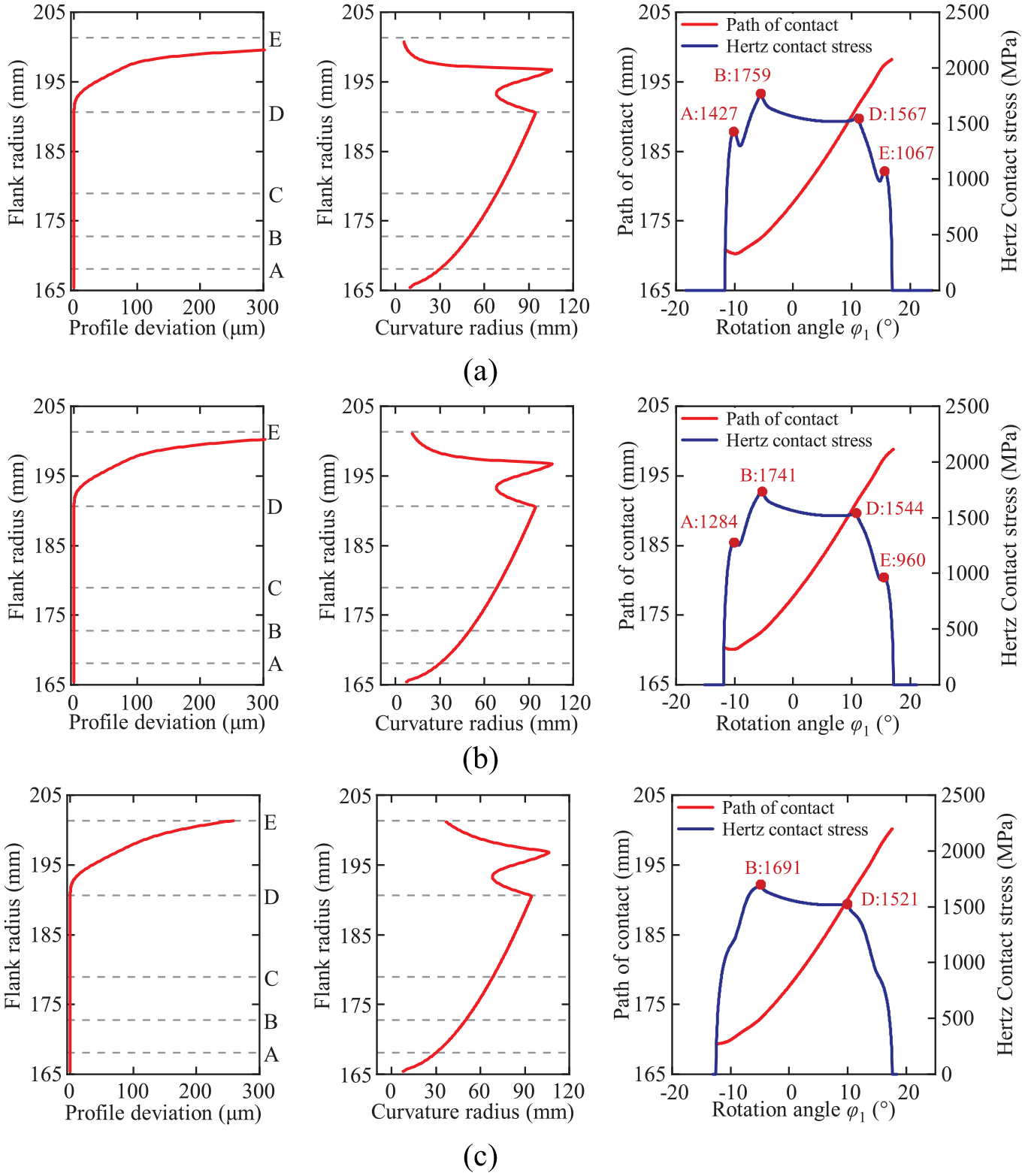
Figure 6 illustrates the profile deviation, curvature radius, and Hertz contact stress along the contact path with arctangent-proportional tip relief, where 50, 5, and 0.5 are selected as representative large, moderate, and small values of c, respectively. As shown in Figure 6(a), the arctangent-proportional tip relief achieves a smoother transition at

The effects on the tooth meshing of arctangent-proportional tip relief with different c. (a) arctangent-proportional tip relief with c = 50, (b) arctangent-proportional tip relief with c = 5, and (c) arctangent-proportional tip relief with c = 0.5.
Equation for the progressive fillet
To reduce double contact of the tooth root and the Hertz contact stress peaks at the transition area between the tip relief region and the tooth tip by the arctangent-proportional tip relief, a progressive fillet is further proposed based on the arctangent-proportional tip relief for a smoother transition, as shown in Figure 7:

where Δs,2 represents the profile deviation by progressive fillet, Xb is the height coordinate of the progressive fillet with the range from 0 mm to lr, rk is the radius of the progressive fillet.

Flank radius versus profile deviation in the progressive fillet.
Figure 8 shows the effects of the geometrical parameter rk of the progressive fillet on the curvature radius, Hertz contact stress, and path of contact. As shown in Figure 8(a), the reductions of the Hertz contact stress at
The effects on the tooth meshing by the progressive fillet with different geometrical parameters rk. (a) rk = mn/3, (b) rk = mn/2, and (c) rk = mn.
Simulation verifications and bench tests
Wear simulation results
The feathers of micro-pitting are the micro-pits on the tooth surface. Therefore, micro-pitting has been evaluated by surface wear in previous studies24,25 and it is demonstrated effective. Cracks causes surface wear but short cracks are discussed in this paper because only they lead to micro-pitting. Based on the Dang Van multiaxial fatigue criterion 37 and the fretting fatigue crack initiation theory, 38 Xu et al. 7 proposed a crack criterion model to predict the crack initiation. The limiting value of the criterion was RS = 1, indicating the initiation of the first cracks on the tooth flank surface. The risk of micro-pitting increases when RS < 1; thus, the crack criterion value RS can also be a safety factor for the tooth flank surface.
The crack criterion is used to predict the initiation of the first crack, regardless of the number of loading cycles. In practice, with an increase in the number of loading cycles, new cracks initiate, and cracks on the tooth flank surface will increase and expand in depth. Besides, surface roughness Ra, sliding velocity vs, rolling velocity vr, surface hardness Hs, and minimum film thickness hmin all affect the wear rate. Based on an empirical formula for calculating tooth surface fatigue wear, 38 Xu et al. 7 proposed a wear rate model including the crack density

where ks and kw are the parameters determined by lubricant and material properties; the subscript R denotes the reference value as listed in Wang et al. 7 ; RaΣ represents the arithmetic mean center roughness by RaΣ = (Ra1 + Ra2)/2; NR is the reference number of load cycle as 106; dV/dN is the wear rate in μm/106 load cycle; and α, β, γ, δ, ε, ζ, κ, and χ are coefficients determined by experiment. It is noted that the parameters about meshing conditions can be obtained by meshing simulation in Section 2.
Thus, the amount of wear after ΔNk cycles is
where the wear amounts are calculated for the profile deviation to evaluate the micro-pitting. Moreover, the wear simulation is carried out based on the newest tooth profile, contact path, and load distribution after certain cycles. This is because too much calculation time is needed if the wear simulation is conducted after every cycle, and the simulation results are unauthentic when all calculations are based on the initial tooth profile. Therefore, the wear can be simulated under different conditions including running-in for micro-pitting.
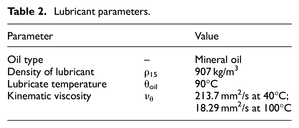
A spur gear pair was chosen for verifying the tooth tip relief method proposed in this paper. The basic gear and the tooth tip relief parameters are listed in Table 1, and the lubricant parameters are listed in Table 2.
Tested spur gear parameters and tooth tip relief parameters.

Lubricant parameters.
Simulation results of a load-stage test according to FVA 54
39
for both linear tip relief and arctangent-proportional tip relief with a progressive fillet are presented in Figure 9. The results for the crack criterion RS show that micro-pitting is concentrated in the area from

Effects on micro-pitting of (a) linear tip relief and (b) arctangent-proportional tip relief with a progressive fillet.
Transmission error is also been studied in this paper. As shown in Figure 10, the transmission error is lower with arctangent-proportional tip relief with a progressive fillet than that with linear tip relief. This is because the arctangent-proportional tip relief leads to a smooth transition between the involute profile and tip relief region. The indicates more stable mesh is also been obtained by this novel tip relief method.

Transmission error of the gear pair with the tip relief methods.
The novel method is to remove the material of the tooth tip for a smoother transition between the involute profile and the tip relief region and between the tip relief region and the tooth tip. The micro-pitting is reduced due to the smaller Hertz contact stress in the transition areas. The main difference between non-standard gears and standard gears is generally the tooth profile. The non-standard tooth profile is input for simulation through the known profile deviations compared with the standard tooth profile (tooth top and root radius of them are the same). Then the tooth tip is designed by this method for smaller Hertz contact stress in the transition areas, thereby micro-pitting is reduced. Thus, this method can also reduce micro-pitting for nonstandard gears based on the suitable parameters.
Test results
The bench tests were carried out by an FZG gear test rig. As shown in Figure 11, the test gears and the driving gears are connected by two flexible shafts, and the Shaft I is loaded with the according weight pieces on the lever arm by a load clutch. The FZG test rig can achieve the power cycle and the motor only needs to supplement the power loss because of friction, etc. Figure 12 is the test rig picture, and the difference between this test rig and standard test rig is three aspects: (1) The center distance is 447.33 mm with the standard distance of 91.5 mm; (2) Load is applied by hydraulic torque motor; (3) 600 L lubricating oil is used compared of standard requirements of 25 L. The modified gears were manufactured using a grinding-wheel dresser with the quality of five. The lubricant is mineral oil with properties in Table 2.

Structure of FZG Gear test rig. 40 (a) structure of FZG test rig and (b) Schematic diagram of the principle of FZG test rig.
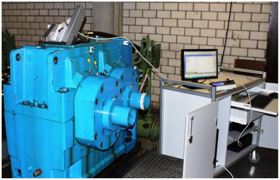
Picture of the test rig.
The procedure of tests was according to the load stage test as specified in FVA 54. 39 In each load stage, the Hertz contact stress at the pitch point should be guaranteed as the specified value by FVA 54. 39 The running time of the 1–5 load stage is about 16 h with the pinion revolutions of 2.1 million, but the time of running-in stage is 1 h with the pinion revolutions of 0.13 million. Moreover, the circumferential velocity is set as 8.3 m/s. The detailed operation conditions of each load test stage are followed as Table 3.
Operation conditions of each load test stage.

Figure 13 shows the measured profile deviations with the proposed tooth tip relief method and the linear tooth tip relief after the loading tests. The measured profile consistent with the simulation results is displayed in Figure 13. The results show that the maximum profile deviation is 11 μm at point

Bench test results of profile deviation after tooth tip relief: (a) the linear tip relief and (b) the arctangent-proportional tip relief with a progressive fillet.
Conclusion
Considering both tooth deformation and tooth tip relief, this study first develops a gear meshing simulation model. The gear contact path, curvature radius, and local Hertz contact stress can be calculated considering the actual contact path despite the tooth tip relief and tooth deformation. In order to eliminate the stress peaks in the transition areas of the tooth flank and thus reduce the micro-pitting of spur gears, arctangent-proportional tip relief, and progressive fillet are proposed. The effects of the key parameters of the tip relief on the gear contact path, curvature radius, and Hertz contact stress are discussed, then the recommended parameters are given. Theoretical simulations and bench tests are carried out to verify the effectiveness of the proposed novel tooth tip relief method in reducing the micro-pitting of the tooth flank. The following conclusions are drawn from this study:
Linear tip relief leads to the reduction of stress peaks at
Arctangent-proportional tip relief achieves a smooth transition between the tip relief region and the involute profile. Furthermore, the Hertz contact stresses at
Progressive fillet reduces the Hertz contact stress peaks at
According to the theoretical wear model and bench tests, this novel tooth tip relief method reduces micro-pitting significantly compared with linear tip relief. Furthermore, the arctangent-proportional tip relief and the progressive fillet reduce the maximum and submaximal micro-pitting, respectively.
With this tooth tip relief method, the stress distribution is improved and micro-pitting phenomena in the tooth flank of spur gears is reduced considerably. Moreover, this proposed tip relief method can be achieved by grinding wheel dressers. And this is also feasible for nonstandard gears. Therefore, the tooth tip relief method proposed in this paper can be used in engineering practice to improve gear stability by reducing micro-pitting.
Footnotes
Appendix
Acknowledgements
The authors acknowledge the support of Beijing Key Laboratory for High-efficient Power Transmission and System Control of New Energy Resource Vehicle and the support of the Fundamental Research Funds for the Central Universities.
Handling Editor: James Baldwin
Declaration of conflicting interests
The author(s) declared no potential conflicts of interest with respect to the research, authorship, and/or publication of this article.
Funding
The author(s) disclosed receipt of the following financial support for the research, authorship, and/or publication of this article: This work is supported by the National Natural Science Foundation of China (Grant Number: 51705012 and 52072018), Key Science and Technology Innovation Project of Shandong Province (Grant Number: 2019JZZY010913 and 2020CXGC011004), Key Science and Technology Project of Guangxi Province (Grant Number: AA19254013), and 2025 Science and Technology Innovation Program of Ningbo (Grant Number: 2020Z026, 2020Z027, and 2020Z028).