
Abstract
The characteristics between the rolling balls and raceways are the key to study a linear rolling guideway (LRG). In this paper, the contact stresses of an LRG with off-sized balls incorporating the variation of the contact angle are given by the established LRG joint model. Moreover, the effect of the location, number, and the deviation degree of the off-sized balls on the stress distribution are studied. In addition, the contact stress distribution between the balls and raceway for different arrangement cases of the off-sized balls are analyzed. The random arrangement case can improve the stiffness and service life of the LRG. Based on the Archard wear theory, the wear prediction model of the LRG is established and the displacements and angular displacements of the slider caused by wear in reciprocating motion are obtained. The effectiveness of the contact stiffness and wear prediction model of the LRG is verified by simulations and analysis.
Introduction
Linear rolling guideways (LRGs), which are the main functional component to achieve low friction feed, are being widely used in machine tools, because of their superior precision-retaining ability, high positioning accuracy, and low friction coefficient, that is, not available with conventional sliding guideways, 1 and its static and dynamic characteristics directly affect the overall performance of machine tools. 2 It is of great significance to study the stiffness and wear of LRGs for optimizing the design and improving its performance.
Considerable effort has been made over the years to study the contact of LRGs. Ohta and Tanaka 3 developed a flexible model that considers the flexibility of the rail and carriage based on Hertz theory. In this model, the deformations of the carriage were estimated by finite element (FE) analysis. In addition, they analyzed the dynamic characteristics of the LRG using analytical and FE approaches in the literature.4,5 Grudziński and Konowalski 6 presented tests on the needle rolling guide to determine the contact deformation characteristics of the guide connections under static loads. A recent paper by Tong et al. 7 established a comprehensive analytical model to calculate the stiffness matrix of a linear ball guide. Sun et al. 8 investigated the effects of preload and static load on the static characteristics of the guideway system using Hertz contact theory, but only the normal stiffness of the guideway is taken into account. Both the vibration tests and the FE simulations studied by Lin et al. 9 revealed that the preload of a linear guideway has a great effect on the vibration characteristics associated with a spindle head. Wei et al. 10 analyzed the effects of different wear types of abrasion on the preload of a ball-screw and the frequency variation for different carriage positions. To predict the characteristics of the spindle system, Liu et al. 11 proposed an analytical model of the spindle contact stiffness based on the multi-scale contact mechanics model and the fractal theory. Xiao and Sun 12 established an explicit approximated expression for contact stiffness according to the numerical simulation results of contact models. Based on the basic parameters of the joint surface, Liu and Huang 13 introduced an analytical model for the cylindrical–spherical joint surfaces and validated by experiments. Using the same basic parameters, a full-load analysis model for the guideway joint was proposed. 14 In the literature, the contact angle of the guideway was constant and the rolling balls were ideal size. Qin et al. 15 developed a mathematical model of the bolted-drum joint stiffness and investigated the effect of the joint and the preload of the bolt on the rotor dynamics. Zhao et al. 16 obtained the changes of the contact stiffness in bolted interface with bolt preload through comparing experiments and FE analysis. Shigeo 17 established a new rolling bearing theory to deal with the relationship between rolling contact fatigue and structural fatigue. The study by Guddei and Ahmed 18 indicated that the rolling resistance has a strong dependence on the surface roughness for the test loads. Zou and Wang 19 studied the contact stiffness variations of linear guideways caused by friction and wear. Tao et al. 20 obtained the contact stiffnesses and displacements of the roller linear guide due to wear in the horizontal, vertical, and around Z-axis, but the contact characteristics around the X- and Y-axis are not mentioned. Kim et al. 21 proposed a model for estimating wear increment and damage accumulation for linear slide rails.
In addition, the dimension errors may exist in LRGs, ball bearings, and ball screws. It should be taken into account that it is difficult to produce identical balls. The ball whose diameter deviates from the nominal size is called off-sized ball. The existing research on the contact stiffnesses and stresses in an LRG usually assumes that the LRG is in ideal condition, and the dimension errors are seldom considered. However, some researchers have studied the dimensional deviation between the balls and raceways in bearings and ball screws. Neisi et al. 22 given a model including the contact deformations, contact forces, and Hertz stresses between each ball and bearing races. The results show that the existence of the off-sized balls alters the contact stiffness and the localized deformation of the race. Chen et al. 23 established a static model to study the effects of dimensional differences among rollers on the bearing load. Zhen and An 24 studied the contact stresses and fatigue life of a ball screw; they found that the ball with errors will change the contact load and affect the dynamic performance of the ball screw. Mei et al. 25 provided a model for the contact load distribution between the balls and grooves in a ball screw with geometry errors under various loads.
The determination of contact loads and stresses between the balls and raceways is an important problem in LRG design. Therefore, it is necessary to study the contact parameters in LRGs. At present, there are few literatures about the dimensional errors in the LRG. The balls with dimensional errors in the LRG will affect the contact loads and stresses, and then affect the joint stiffnesses and service life of the LRG. In this paper, the model of an LRG joint with off-sized balls considering the variation of contact angle is proposed, and the contact deformation, load, stiffness, and maximum stress between the balls and raceways on the basis of the Hertz contact model is studied. The loads distribution of the LRG with off-sized balls is different from that with ideal size, thus affecting the contact stresses of the LRG. For this reason, the study investigates the effects of one or multiple off-sized balls on the deformation, load, and stress distribution in the LRG. Furthermore, the location, number, and the deviation degree of the off-sized balls on the contact load and stress effect, as well as the contact stress with different arrangement of off-sized balls in the LRG are studied. Finally, the wear process of the LRG is analyzed and the tangential and normal displacements and pitch, yaw, and roll angular displacements of the slider caused by wear are obtained. The effectiveness of the proposed contact stiffness and wear prediction model of the LRG is verified by simulations and analysis.
LRG joints model
The schematic of an LRG joint is illustrated in Figure 1. As shown in Figure 1, the LRG can withstand the tangential load
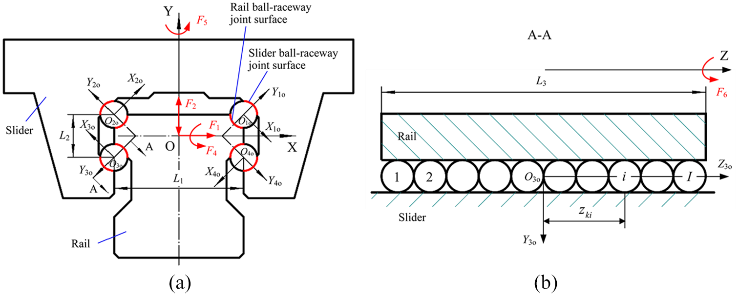
Schematic of an LRG joint: (a) front view and (b) A-A cross-section.
In the current study, the LRG joints model is based on the following assumptions:
The shapes of the rolling balls and raceways remain their original shapes;
The rail and slider are supposed to be rigid because the deformations of the rail and slider under the external loads is significantly smaller than those of the ball–raceway joint surfaces;
All contact deformations of the ball–raceway joint surfaces are in elastic range.
Model of LRG joints with off-sized balls
As far as off-sized balls are concerned in the LRG, the rolling ball diameter needs to be defined as follows:

where

where
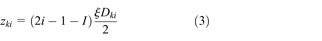
The equation that describes the position of each ball in Z-direction is as follows:
Under the external loads, the displacements result from the deformations of the slider and rail ball–raceway joint surfaces are

where


where

where
For an LRG with the nominal contact angle of
Figure 2 shows the ball–raceway joints contact under the normal compressive load considering the change in contact angle. In Figure 2,


Ball–raceway joints contact under the normal compressive load: (a) left-side and (b) right-side.
The normal tensile load on the LRG is opposite to the normal compressive load, so the change of the contact angle is opposite to that when the normal compression load is applied. That is, the contact angles of the balls and raceway in the first- and second-rows decrease under the normal tensile load, while those in the third- and fourth-rows increase.
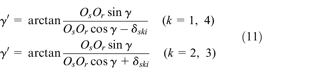
The ball–raceway joints contact under the tangential load considering the change in contact angle is displayed in Figure 3. The contact angles in the second- and third-rows decrease, while those in the first- and fourth-rows increase. The contact angle can be obtained as follows:


Ball–raceway joints contact under the tangential load: (a) left-side and (b) right-side.
As a pitch moment is applied to the LRG, because of the small deformation, the load on each ball–raceway joint surface may be equivalent to the case when the LRG withstand different normal tensile or compressive loads (the slider bears different compression loads in positive Z-direction, tensile loads in negative Z-direction, or vice versa), so the change of the contact angle of the LRG under pitch moment is similar to that of the LRG bearing normal load. In the same way, when the external load is yaw moment, the change of the contact angle is similar to that of the LRG under different tangential loads.
Figure 4 illustrates the ball–raceway contact under the roll moment considering the change in contact angle. In Figure 4, the red dotted line is the deformed slider, and

According to the above analysis, the displacement

where Ksn and Krn refer to the contact stiffness between the ball and raceway.

Ball–raceway joints contact under the roll moment: (a) left-side and (b) right-side.
Contact stress
In the matter of the ball and slider raceway contact, the maximum Hertz stress is at the geometric center of the contact based on Hertz contact model, which can be given by: 28

where a and b are respectively the major and minor semi axis of the contact ellipse.

where

where

where
Load model of LRG joints
On the basis of the reactive force matrix


The sum of
Case studies
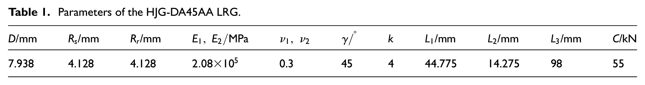
The relative parameters of the type HJG-DA45AA LRG are listed in Table 1. C is the basic rated dynamic load of the LRG, and the light, medium, heavy preload are 0.02C, 0.07C, 0.12C, respectively. The materials of the ball, slider, and rail are all GCr15. Assuming that there are no errors in the slider and rail raceways, only dimension errors of the ball are considered.
Parameters of the HJG-DA45AA LRG.
Results in the LRG without an off-sized ball
It is assumed that the external loads are F1 = 3000 N, F2 = 1500 N, F4 = 200 Nm, F5 = 100 Nm, and F6 = 50 Nm. The contact deformation distribution without an off-sized ball between the four rows of balls and slider raceway for preloaded LRG is depicted in Figure 5. It can be seen that the deformation distribution among four rows of balls is not uniform, and the deformation of each ball is different. Due to the combined action of loads and moments, although the contact deformations of the first and third rows have a slight change, those of the second and fourth rows change obviously and they hold opposite variation trend. Figure 5 also indicates that the LRG with higher preload has larger contact deformation between the balls and raceway.
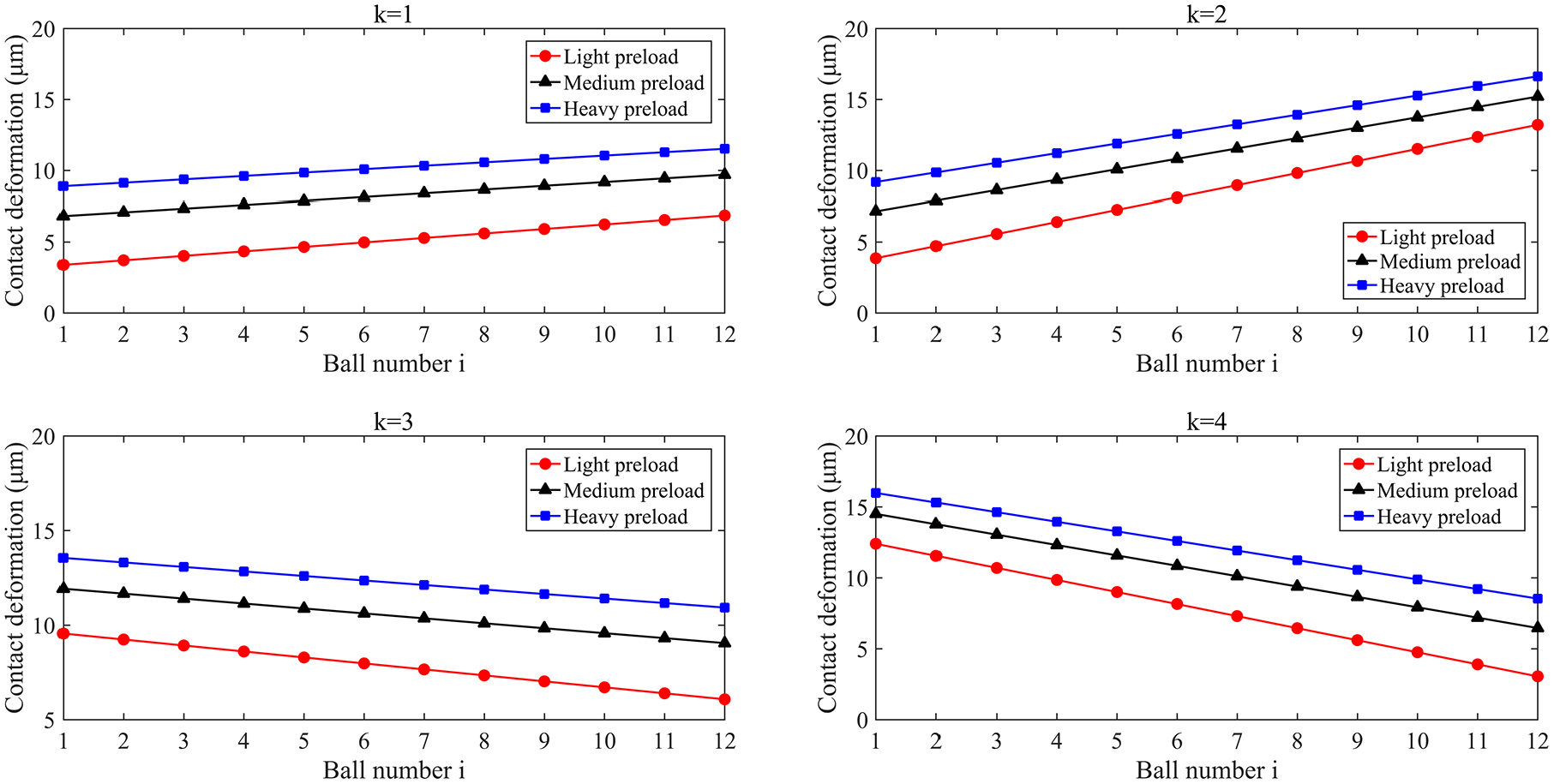
Deformation distribution without off-sized balls.
Figure 6 depicts the contact load distribution without an off-sized ball between the balls and slider raceway. Because of the Hertz contact relationship between the load and displacement, the contact load changes nonlinearly with the contact deformation.

Load distribution without off-sized balls.
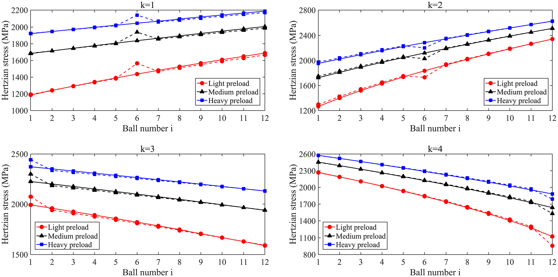
The maximum Hertz contact stress distribution without an off-sized ball between the balls and slider raceway is illustrated in Figure 7. From Figure 7, the effects of the external loads on the contact performances of each ball in each row are not the same. For example, in a certain preload state and the normal tensile load, the contact loads on balls and raceway in the first- and second-rows decrease, while the contact load in the third- and fourth-rows increases. For this reason, the ball positions of the maximum contact parameters in each row are not the same, and the value of the maximum contact parameters are also different. The ball number 12 in the first-row (Figure 7 (k = 1)) experiences highest Hertz stress equal to 1688, 2006, and 2186 MPa (light, medium, and heavy preload), respectively. The maximum stress in the second-row (Figure 7 (k = 2)) is also experienced in the ball number 12, and the contact stresses are respectively 2341, 2512, and 2627 MPa. The highest stress in the third-row (Figure 7 (k = 3)) is found in ball number 1, and the stresses are 1991, 2225, and 2372 MPa, respectively. Meanwhile, the maximum Hertz stress in the fourth-row (Figure 7 (k = 4)) is ball number 1, and the stresses are respectively 2268, 2453, and 2576 MPa. The specific contact characteristic parameters are listed in Table 2. In addition, the higher the preloaded LRG brings about the smaller the change of the contact stress.

Stress distribution without off-sized balls.
Maximum contact parameters in each row.

Contact stresses in the LRG with off-sized balls
The stresses of each ball in each row for the medium preloaded LRG are studied for the cases where only one or multiple balls are larger or smaller than the others balls. The off-sized balls in the LRG affect the contact load and stress. For the case of low requirements in practice, the dimensional deviation of the balls can reach 2 μm, while for high requirements, the dimensional deviation is within 1 μm. Therefore, according to the actual situation, the effect of the off-sized balls of ±1 and ±2 μm on the contact stress between the ball and raceway is analyzed.
Results with one off-sized ball
In order to investigate the influence of the off-sized ball on the contact load and stress distribution, the location of the ball must be considered. The effect of different dimensional deviations at the same location on the contact characteristics of each ball and raceway is also different.
Suppose that the LRG has only one ball with dimensional error, and this ball is located in ball number 6 of the first-row. The external loads are F1 = 3000 N, F2 = 1500 N, F4 = 200 Nm, F5 = 100 Nm, and F6 = 50 Nm. The Hertz stress distribution without off-sized ball and with only one off-sized ball for the medium preloaded LRG is depicted in Figure 8. The load and stress distribution of the LRG is different from that of the LRG with the nominal size due to the off-sized ball. When the ball number 6 in the first-row has 1 or 2 μm positive errors, a clear increase in the Hertz stress can be observed, and the stress increases from 1836 MPa to 1940 or 2037 MPa (Figure 8 (k = 1)). In addition, a certain amount of energy is needed to resist the deformation of the LRG. Because the total energy transferred in the LRG remains unchanged, the off-sized ball bears higher load than others, and the stress variation is the same as the load. As shown in Figure 8 that the contact stress of the ball number 6 in the first-row is increased by 5.6% (1 μm positive error) or 11% (2 μm positive error), and other balls in the first-row are reduced by about 0.4% or 0.8%. The larger the positive dimension error with an off-sized ball bring about the higher contact stiffness and stress. Besides, the off-sized ball in the first-row also leads to slight changes in the contact stress of the other three rows of balls. It is assumed that there are no errors in the slider and rail raceways, only dimension errors of the ball are considered. Therefore, when the ball number 6 in the first-row has 1 or 2 μm positive errors and other balls are nominal diameter, the diameter of the off-sized ball is larger than others, which makes the contact pressure and stress of the ball increase. The larger the positive error is, the larger the contact pressure and stress are.
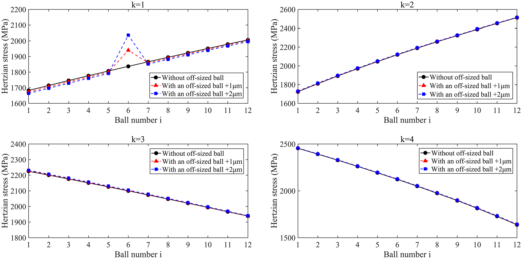
Stress distribution with one positive error ball for the medium preloaded LRG.
The above describes the case that the diameter of the off-sized ball is larger than the ball’s nominal diameter. Of course, the off-sized ball may also have a smaller diameter, so the stiffnesses and stresses are decreased. The contact stress distribution of the rolling balls withstanding the external loads are shown in Figure 9, since there is only one off-sized ball having a diameter 1 or 2 μm smaller than the ball with nominal size. The presence of the off-sized ball will reduce the contact stress of the studied ball but will slightly increase the stresses of the adjacent balls. Moreover, the off-sized ball in a row experiences lower force, while the other balls in the same row carry the higher load. When the ball number 6 in the first-row has 1 or 2 μm negative errors, the contact stress decreases from 1836 MPa to 1727 or 1607 MPa (Figure 9 (k = 1)). It can be observed in Figure 9 that the Hertz stress of the ball number 6 in the first-row is decreased by 6% (1 μm negative error) or 12% (2 μm negative error), and other balls in the first-row are increased by about 0.4% or 0.7%. Furthermore, the off-sized ball in the first-row also brings about slight changes in the contact stress of the other three rows of balls. When the ball number 6 in the first-row has 1 or 2 μm negative errors and other balls are nominal diameter, the off-sized ball is smaller in diameter than others, which leads to the decrease of contact pressure and stress of the ball. The larger the negative error is, the smaller the contact pressure and stress are.
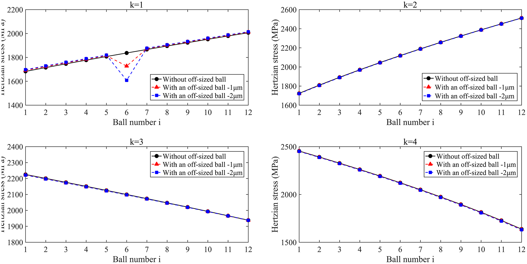
Stress distribution with one negative error ball for the medium preloaded LRG.
It should be noted that the larger the negative dimension error in the off-sized ball leads to the smaller contact stress. When the size of the off-sized ball is too small to a certain value, the ball will break away from the raceway. In this case, the diameter of the ball is so small that the contact deformation, load, and stress between the off-sized ball and raceway will be zero under the external loads, so the ball will not work on the LRG system, as shown in Figure 10. At this time, the other balls will bear more load and stress, which will cause vibration of the LRG and speed up the wear of the raceway.

Stress distribution of one off-sized ball with negative error reaching the limit for the medium preloaded LRG.
Results with multiple off-sized balls
There may be multiple off-sized balls in the LRG in practical engineering and these rolling balls might have different sizes and locations. The differences in the sizes and locations of the off-sized balls affect the contact stiffnesses and stresses of the LRG.
Preloaded LRG having four off-sized balls in the four rows depicted in Figure 11 was investigated. The solid lines in the figure represent the stress distribution without dimensional error balls, and the dotted lines represent the stress distribution with dimensional error balls. The ball number 6 in the first-row and number 1 in the third-row have 1 μm positive error, and the ball number 6 in the second-row and number 12 in the fourth-row have 1 μm negative error. As shown in Figure 11, different sizes and locations of the off-sized balls have different effects on the contact stresses between each ball and the raceway in each row of the preloaded LRG. Consistent with the study in the previous section, the diameter of the off-sized ball with positive error increases, the contact stress increases, and the contact stress of the adjacent balls in the same row decreases correspondingly. On the contrary, the diameter of the off-sized ball with negative error decreases, the contact stress decreases, and the contact stress of the adjacent balls in the same row increases. Moreover, the dimension error balls in one row have an impact on the contact stress between the balls and raceway in the other three rows. In addition, the contact stress distribution of the light, medium and heavy preloaded LRG with the same sizes and locations of off-sized balls is also depicted in Figure 11. The lower the preload of the LRG leads to the greater the change of contact stress between the ball and raceway, indicating that the LRG with lower preload is more sensitive to the change of the dimensional deviation of the ball.
Stress distribution with multiple dimension error balls.
When the external loads are changed to F1 = 3000 N, F2 = −1500 N, F4 = −200 Nm, F5 = 100 Nm, and F6 = 50 Nm, the contact stress distribution with four off-sized balls located in the four rows on the light, medium, and heavy preloaded LRG are illustrated in Figure 12. Similarly, the solid lines in Figure 12 denote the stress distribution without dimensional error balls, and the dotted lines denote the stress distribution with dimensional error balls. The sizes and locations of the off-sized balls are the same as those in Figure 11. As shown in Figure 12, due to the variation of the external loads, the contact stress distribution trend is different from that in Figure 11, but the effect of the dimension error balls on the contact stress distribution is similar. When the diameter of the off-sized balls is larger than the nominal diameter, the contact stress between the off-sized balls and the raceway increases, and the contact stress of the adjacent balls in the same row decreases. On the contrary, when the diameter of the off-sized balls is smaller than the nominal diameter, the contact stress between the off-sized balls and the raceway decreases, and the contact stress of the adjacent balls in the same row increases.

Stress distribution with multiple dimension error balls with different external loads.
Stress in the LRG with different arrangement of off-sized balls
The diameters of the rolling balls in the LRG usually differed from one another in practical applications, so it was of great value to study the influence of the arrangements with off-sized balls on the contact parameters of the LRG. This paper studied three cases, namely, the off-sized balls were arranged in order of large to small, small to large, and random. Using the random function in MATLAB, the random order of the balls was obtained. When the diameter error range of the balls is ±1 μm, a list of the dimension errors for each ball in each row of random balls is shown in Figure 13.

Schematic of diameter errors of balls.
It is assumed that the external loads are F1 = 3000 N, F2 = 1500 N, F4 = 200 Nm, F5 = 100Nm, and F6 = 50 Nm. In order to better identify the change of the contact load and stress in the medium preloaded LRG with and without off-sized balls, the contact load in the balls bearing the external loads under three different conditions is shown in Figure 14: Case I: without off-sized balls, Case II: balls are arranged from small to large, Case III: balls are arranged from large to small, Case IV: balls are arranged randomly. The maximum Hertz stress distribution for the medium preloaded LRG in the three arrangements is depicted in Figure 15 and compared with the case that without off-sized balls. It can be found that the arrangements of the off-sized balls affect the contact load and stress distribution greatly.

Load distribution for the medium preloaded LRG in different arrangements. Case I: without off-sized balls, Case II: balls are arranged from small to large, Case III: balls are arranged from large to small, Case IV: balls are arranged randomly.

Stress distribution for the medium preloaded LRG in different arrangements. Case I: without off-sized ball, Case II: balls are arranged from small to large, Case III: balls are arranged from large to small, Case IV: balls are arranged randomly.
Figures 14 and 15 (k = 1 and k = 3) show that the load and stress distribution of the off-sized balls arranged randomly is more uniform than the balls arranged from large to small and small to large, and the LRG is more stable and reduces vibration. When the off-sized balls are arranged from large to small, the variations of the load and stress between the balls and raceway in the second-row are the smallest, but the variations are the largest in the fourth-row. On the contrary, when the off-sized balls are arranged from small to large, the variations of the load and stress in the second-row are the largest, but the variations in the fourth-row are the smallest. For this reason, the load and stress distribution between the balls and raceway of the LRG in which the off-sized balls are randomly arranged are more uniform, which can improve the static stiffness and service life of the LRG.
Analysis of the LRG joints model
The LRG joints model with off-sized balls considering the effects of contact angle is compared with the LRG joint stiffness testing method proposed in literature, 14 and the results for medium preloaded HJG-DA35AA LRG are as shown in Figure 16.

Stiffness curves comparing the experimental and simulated results of the LRG joint: (a) tangential load–stiffness curves, (b) normal compressive load–stiffness curves, (c) normal tensile load–stiffness curves, (d) pitch moment–angular stiffness curves, (e) yaw moment–angular stiffness curves, and (f) roll moment–angular stiffness curves.
It can be seen from Figure 16 that the simulated results of the LRG joints model with off-sized balls considering the effects of contact angle are very close to the experimental results, and the proposed model can describe the contact characteristics of the LRG joints. With the increase of the external loads or moments, the stiffnesses, or angular stiffnesses of the LRG increases slightly. In addition, the roll angular stiffness is obviously lower than other stiffnesses, which indicates that the LRG has poor ability to bear the roll moment.
Wear prediction of LRG
The wear of LRG is related to the loads, and off-sized balls will aggravate the wear of LRG. Therefore, combined the contact deformations and loads between off-sized balls and raceways, we establish the wear model of LRG considering the off-sized balls under the tangential and normal loads, and the pitch, yaw, and roll moments in this section.
According to Section 3.3, it is more suitable to select randomly arranged balls for LRGs, and the range of diameter error of the balls is ±1 μm. The normal loads between the balls and raceways are different, and the off-sized balls also affects the loads.
Wear prediction model of LRG
The amount of volume loss of the raceway due to abrasive wear based on the Archard wear theory is established as follows:
where K represents the adhesive wear coefficient, obtained by experimental results,
20
L is the sliding distance,
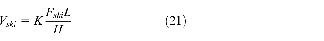
In the contact surface formed by the two contact bodies, the micro-elastic sliding phenomenon caused by the relative deformation of the material between the corresponding particles is called creep. An LRG is accompanied by creep during the operation. For this reason, the sliding distance L of the rolling ball can be calculated by:

where η is the creepage of the ball, and S is the running distance of the slider. The creepage η is related to the running speed v of the slider, the rotation velocity ω of the rolling ball, and the distance

The contact area between the ball and raceway is:

where a and b are the major and minor semi axis of the contact elliptic calculated by Section 2.2.
Therefore, in combination with equations (21) and (22), the vertical wear of raceway is expressed as follows:

According to the above analysis, combined with the structural characteristics of the LRG, the wear prediction model under different kinds of loads and moments is established:

where
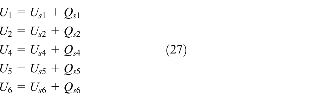
It can be seen from equations (26) and (27) that the wear and accuracy change of the LRG can be predicted by analyzing the deformation of the slider under the external loads and the displacements caused by wear. The model optimizes the design of the LRG.
Analysis of the wear prediction model
According to the wear prediction model of the LRG, the displacements and angular displacements of the slider are plotted when the LRG runs at different running distances under the tangential and normal loads, and pitch, yaw, and roll moments as shown in Figure 17.
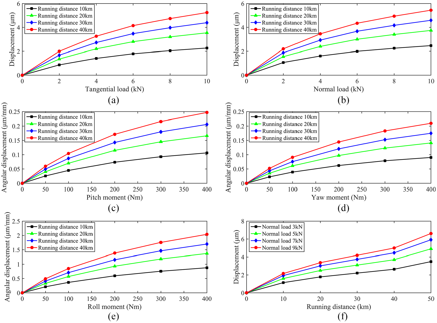
Simulated results of the wear prediction model of the LRG: (a) curves of tangential displacement with tangential load at different running distances, (b) curves of normal displacement with normal load at different running distances, (c) curves of pitch angular displacement with pitch moment at different running distances, (d) curves of yaw angular displacement with yaw moment at different running distances, (e) curves of roll angular displacement with roll moment at different running distances, and (f) curves of normal displacement with running distance under different normal loads.
From Figure 17(a) to (e), it can be seen that the displacement or angular displacement of the slider increases nonlinearly with the increase of load or moment at the same running distance, and the larger the load or moment is, the slower the displacement or angular displacement increases. Moreover, under the same external load, the farther the running distance is, the larger the displacement or angular displacement of the slider is. In addition, Figure 17(f) depicts the three stages of normal wear of the LRG: in the initial motion stage of the LRG, due to the surface roughness, the contact area of the asperity is small, the contact stress is large, and the wear speed is fast; in the normal operation stage of the LRG, the actual contact area increases and the pressure decreases. At this time, the wear has stabilized; in the last stage of severe wear, the wear rate increases sharply due to the great change of friction conditions. At this time, the mechanical efficiency and the accuracy is reduced, and the vibration occurs, which finally leads to the complete failure of the parts. The wear prediction model established in this paper corresponds to each stage of the wear of the LRG and can correctly describe the change of the wear of the slider in the process of reciprocating motion under the external load.
Conclusions
Through the above analysis of the contact load and stress distribution of the LRG with off-sized balls, the stiffness of the LRG joints, and the wear prediction model of the LRG, the following conclusions can be obtained:
The contact deformations, loads, and stresses are not uniformly distributed amongst four rows of balls of the LRG. The positive size deviation of the off-sized balls brings about the increasing of the contact stress, while the off-sized balls with negative errors decrease contact stress.
The contact load and stress distribution of the off-sized balls arranged randomly are more uniform than those arranged from large to small or from small to large, which can reduce the vibration of the LRG and improve the stiffness and service life of the LRG.
The wear prediction model of the LRG was established based on the Archard wear theory, and the displacements of the slider along the X- and Y-axis and the angular displacements of the slider around the X-, Y-, and Z-axis due to wear were obtained. The correctness of the established wear prediction model of the LRG is verified by simulation analysis.
The stiffness calculation model and wear prediction model of LRG proposed in this paper can be used to guide the design and development process of the LRG and improve its performance and reliability.
Footnotes
Appendix
Handling Editor: James Baldwin
Declaration of conflicting interests
The author(s) declared no potential conflicts of interest with respect to the research, authorship, and/or publication of this article.
Funding
The author(s) disclosed receipt of the following financial support for the research, authorship, and/or publication of this article: This work was supported by the National Natural Science Foundation of China (grant no. 51375379) and the National High Technology Research and Development Program of China (863 Program, grant no. 2012AA040701).