
Abstract
Aiming at the problems of the general involute external gear pump, a gear pump with double circular arc helical gear as motion pair is proposed. Based on the comparison and analysis of their meshing characteristics, the advantages of contact strength, bending strength, and transmission stability are significant with the double circular arc helical gear as motion pair. Taking the sine curve as the transition curve and on the basis of the conjugate principle of gear meshing, the surface tooth profile equation of double circular arc helical gear is given out by coordinate transformation. The equal area method is used to deduce the displacement of double circular arc gear pump, then the maximum and the minimum instantaneous displacement of the double helical gear pump are solved, thus the theoretical pulsation tends to 0. Using Fluent three-dimensional dynamic mesh technique, by comparing and simulating the flow pulsation of double circular arc helical gear pump and ordinary involute helical gear pump of the same gear parameters, it is concluded that the flow pulsation of the double circular helical gear pump is much smaller than that of the involute helical gear pump. In summary, this article provides reference for design of high-performance gear pump.
Keywords
Introduction
As the external gear pump has the characteristics of a simple structure, easy fabrication, low cost, small size, good pollution resistance, and self-suction capacity, it has been widely used in the industrial field. However, due to the flow and pressure fluctuations, large noise, radial force imbalance, and other issues, to some extent, its range of use has been limited. 1 In view of the above problems, scholars at home and abroad have put forward some solutions in order to reduce the flow pulsation of gear pump, for example, J Zhang et al., 2 G Yang et al., 3 and others adopt helical gear instead of spur gear drive, and A Song et al. 4 used a gear with an arc shape along the width of the tooth instead of the straight gear drive which effectively improved the flow pulsation problem. The single circle arc gear pump proposed by Y Liu et al. 5 has no pulsation in theory, but the machining of the gear is complicated and the bearing capacity is low; A “silent gear pump” of Rexroth was exhibited at the 2011 exhibition in Hannover, it is a double circular arc helical gear pump, the noise is reduced by 15 dB(A) on average as compared with standard external gear pumps, and moved to bass, the flow and pressure pulsation is far lower than that of common gear pump, it is equivalent to the internal gear pump. 6 At present, there is no systematic theoretical analysis of the displacement calculation method and the flow pulsation characteristics of the double circular helical gear pump and mature domestic products. Based on the advantages of this pump, it can be predicted that it will have great potential in the future.
Taking the double circular helical gear pump as the object, the theoretical displacement calculation formula of the pump is derived from volume change method, and the pulse characteristics can be obtained by comparing the maximum instantaneous displacement and minimum displacement. Taking the sine curve as the transition curve, and based on the principle of gear conjugation, the tooth profile equation of the double circular arc helical gear can be obtained, which provides a theoretical basis for the research and development of the double-arc helical gear pump.
Double circular helical gear and meshing principle
The double circular arc gear is a point meshing gear whose tooth profile is circular arc, and the convex and concave tooth profiles of two single circular arc gears are combined with the tooth profile of the gear, which is composed of two sections of arcs and a section of transition curves. As shown in Figure 1, the arc a1b1 is the addendum arc, the arc ba is the root arc, and the radius of the two arcs is equal (in order to avoid the jamming and noise in the meshing process, the radius of the circle of the tooth root is slightly larger than the radius of the addendum circle in the actual manufacture), and the center of the arc is on the pitch circle. The curve b1b is the transition curve, which is respectively tangent to the addendum arc and the root arc, respectively, at the b1 point and the b point (the transition curve can be the straight line, parabola, sine line, cosine line, etc. 7 ).

End-tooth profile of double circular arc gear.
The double circular arc gear drive has only a little contact in the same end section, in order to guarantee the continuous transmission, the helical gear must be made of oblique teeth, and the helical angle of the two gears is equal in magnitude and opposite in direction, the axial coincidence degree is greater than 1. Double circular helical gear drive has the advantages of higher contact strength and bending strength, long service life, and simple processing technology; 8 therefore, the double circular arc helical gear instead of the ordinary involute gear used as the gear pump pair has a great advantage both in stability, torque, and service life than the ordinary involute gear.
Double circular arc helical gear transmission is one point continuous meshing transmission, that is, as the gear rotates, the front face is disengaged from meshing, and the subsequent profile of the cross section enters the meshing, and the contact point moves along the same height along the axis. As the tooth surface has two segments of arc, there are two contact traces on the corresponding tooth surface, and at least two contact points exist at the instantaneous tooth surface (in Figure 2, “1” and “2” two points), and each point keeps a fixed distance and moves along the axis at the same time.
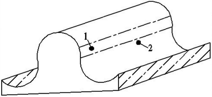
Contact point distribution of double circular arc gear.
The overlap coefficient of common involute gear should be greater than 1 and less than 2, which means that the process of gear transmission is sometimes a pair of tooth meshing, sometimes two pairs of teeth are engaged, and the design of double circular arc helical gears with the overlap coefficient greater than 2, the operation process is always greater than two of the tooth, so the bending moment of each tooth is smaller. At the same time, the equivalent curvature radius of double circular arc gears is several times larger than the equivalent curvature radius of involute gears, so the contact stress will decrease greatly, and the contact strength will be greatly improved.
As shown in Figure 3, using the transient dynamic analysis module in finite element software ANSYS Workbench, the double circular arc helical gear transmission and the involute gear transmission with the same gear parameters are compared and analyzed. The same load is applied to them, and the equivalent of double circular arc helical gear transmission should be much smaller than the equivalent stress of involute helical gear transmission.
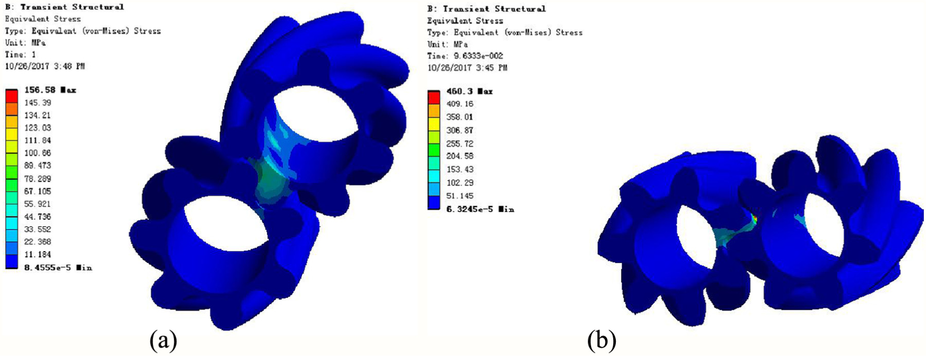
Equivalent stress of gear transmission. In this figure, (a) is ‘Equivalent stress analysis of involute gear’, and (b) is ‘Equivalent stress analysis of double-circular-arc gear’.
As shown in Figure 4, the meshing line of the double circular arc helical gear is an “8” word line and the concave meshes with convex all the time, which is the same as the internal meshing gear meshing characteristic. The contact stress of the tooth surfaces is much smaller than the convex surfaces, and the relative sliding distance is shorter, so the double circular arc helical gear has the longer life.9,10 At the same time, when the double circular arc helical gear is engaged, the gear’s top and root are also engaged. The continuous tooth contact reduces the working noise. The constant contact of the tooth faces almost transfers the hydraulic fluid in a continuous and silent way.

Meshing lines of double circular helical gears.
The gear overlap ratio of the ordinary involute external gear pump is greater than 1. When the first pair of teeth has not yet been separated from the engagement, the other pair of teeth has entered the engagement. When two pairs of teeth are meshed at the same time, they form a closed dead volume that is not connected with the suction and pressure chamber, which is called the trapped oil phenomenon (as shown in Figure 5(a)). The gear engagement mode of the double circular arc helical gear pump is a continuous one. The overlap ratio of the end face is less than 1, and the axial coincidence degree is more than 1; therefore, trapped oil phenomenon will not happen (as shown in Figure 5(b)). It overcomes the additional load caused by the trapped oil phenomenon and reduces the wear, vibration, and noise of the machine parts. 11
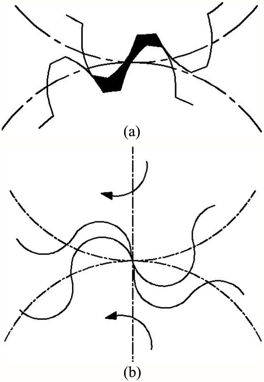
Sketch map of double circular arc tooth profile and involute tooth profile. In this figure, (a) is ‘The involute gear driving’, and (b) is ‘The double-circular-arc gear driving’.
Design of end-face tooth shape of double circular helical gear
To design the tooth profile of double-arc helical gear, the transition curve must be determined first,12,13 and the transition curve has a variety of choices, of which the gear ring curve with sinusoidal curve is short, the effective tooth height is high, and the output displacement is large. 14 At the same time, the smaller angle of pressure can be chosen to reduce the load on the bearing, which creates the condition for the high pressure of the pump. The equation of the end-face profile with the sine curve as the transition curve is designed as follows.
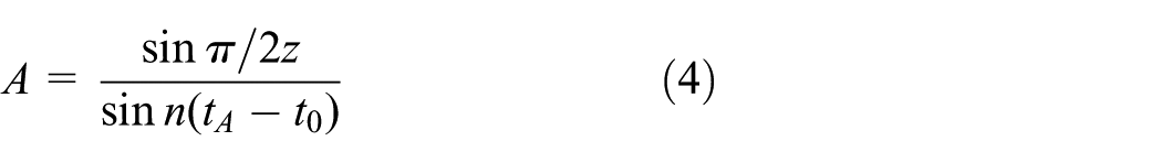
As shown in Figure 6, the driving wheel O1 and driven wheel O2 have the same pitch circle, taking the O1 driving wheel center as a ray-intersecting pitch circle at A, ∠AO1P = β = π/2z, and an arbitrary sine curve L over A point is
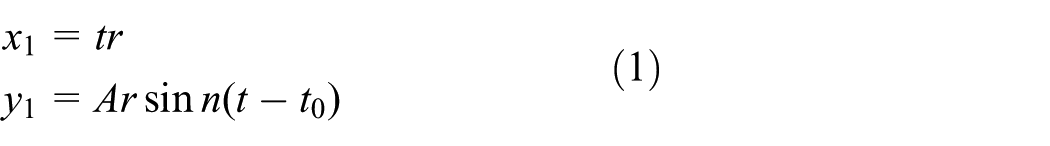
In the formula, r is the pitch radius of gear, t is the parameter variable, t0 is the initial value, A is the control coefficient of transition curve to the maximum value of x axis, and n is the constant of controlling the period of sinusoidal curve.

Double circular arc end-face meshing analysis diagram.
Let us assume that the tangent of the A point on the sine line L corresponds to the X-axis at point D, make point A pressure angle is α, as illustrated in Figure 6, ∠ADP = β + α.
For point A

By the formula (2), it can be seen

Due to the slope of the tangent AD

If x1 = 1.5r, namely, n(1.5–t0) = π/2, the function y had a maximum value, it can be seen

By substituting formulas (4) and (6) into the formula (5), it can be obtained as follows

To sum up, when the number of teeth z and the pressure angle α are known, as shown in Table 1, n, tA, and t0 can be solved, then a sinusoidal curve L can be obtained.
When the pressure angle α is 14.5°, the relationship of tA, t0, n, tE, and f1 under different tooth number z.

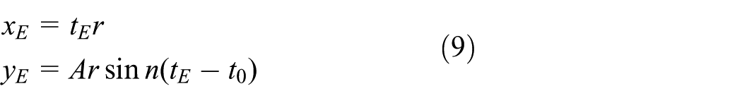
Take the point E in the sine curve L and make the normal over node P (r,0). Then its normal equation can be assumed

The coordinate of point E
By substituting formulas (2), (5), and the coordinate of point P into the formula (8), it can be obtained as follows
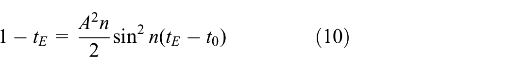
As shown in Figure 6, take the node P as the center of the circle and PE as the radius to draw the arc
Thus, the circular arc radius r1 of the tooth tip (root) can be obtained

Because of r = mz/2.
It can be assumed

In the design of gear pairs in gear pumps, it is believed that the pressure angle is 14.5°, which is beneficial to reduce the bearing load, radial force, and improve the comprehensive performance of the pump. When the pressure angle is 14.5°, the values of tA, t0, n, tE, and f1 under different tooth number z are shown in Table 1.
After determining a curve equation on gear O1, through the meshing principle of gear engagement,15–18 a curve equation of conjugate on the gear O2 is obtained. The curve equation of gear O1 can be obtained by a curve equation on gear O2 too. The specific solution is as follows.
As shown in Figure 7(a), the coordinate system S1 (O1x1y1z1) and S2(O2x2y2z2) are the two fixed-space coordinate systems of gear meshing, and the z1 axis and the z2 axis coincide with the axis of the two gears, respectively. The x1 axis coincides with the x2 axis, and their direction is the shortest direction of the two axis, that is, 2r of the center distance.

The spatial coordinate system of double circular helical gear meshing drive. In this figure, (a) is ‘Spatial coordinate system of double circular helical gear meshing drive (The angle of the gear rotation is θ)’, and (b) is ‘Spatial coordinate system of double circular helical gear meshing drive (The angle of the gear rotation is θ+β)’.
The coordinate systems Sm(O1xmymz1) and Sn(O2xnynz2) are the coordinate systems that are fixed with two gears, which coincide with the coordinate system S1 and S2, respectively, at the start position. The gears rotate around the z1 axis and the z2 axis, respectively, after a period of time, the two gears rotate to the position shown in Figure 7(a), assuming that the gear corresponds to a rotation angle of θ, according to the coordinate relation shown in the diagram, the transformation matrix Mnm from the coordinate system Sm(O1xmymz1) to Sn(O2xnynz2) can be obtained

In the plane coordinate system x1O1y1, the curve EA1 is a conjugate curve generated by the curve EA in the conjugate motion of the gear meshing, and the equation in the plane coordinate system x2O2y2 can be obtained by the coordinate transformation matrix Mnm

By substituting the equation of the curve EA1 into the formula (14), it can be obtained as follows

Similarly, as shown in Figure 7(b), the gears continue to rotate around the z1 axis and the z2 axis, respectively. After a certain period, the coordinate system moves to Sh (O2xhyhz2) and Sp (O1xpypz1), the gear corresponding to the rotation is β + θ at this moment, according to the coordinate relation shown in the diagram, the equation of the curve

As shown in Figure 6, in the plane coordinate system x1O1y1, the normal point of the E point on the curve is over the node P, and the PE is the radius of the tooth root arc, and the equation of the arc CE of the root tooth is

Through coordinate transformation and meshing principle, the equation of the arc

The meshing line is the set of theoretical contact points on the gear tooth surface in the fixed coordinate system. The coordinate in the moving coordinate system is converted to the coordinate value in the fixed coordinate system, which is the meshing line equation, so the meshing line equation of PE part can be obtained by coordinate transformation

So far, the tooth profile equation of double circular arc helical gear pump with a sine curve as the transition curve is solved by the coordinate transformation and meshing principle.
Displacement calculation and pulsation analysis of double circular arc helical gear pump
First, adopting volume change method to analyze the instantaneous displacement of the double circular arc helical gear pump. 19 As shown in Figure 8, using equal area method to analyze. The irregular graphics area of curve ABO swept the angle dψ with O as the center (the shaded part) is OA2/2dψ, which is the same as the fan area of the curve endpoint radius OA swept at the same angle dψ.

Area of curve ABO rotation swept.
As shown in Figure 9, the gear rotates


Meshing analysis diagram of double circular arc straight gear pump.
The discharge volume of the oil pressure chamber can be obtained

In the formula, r is the nodal radius of a double circular arc gear (r = (a + Δa)/2, a is gear center distance and Δa is gear center distance error), ra is the radius of the tooth top circle of a gear,
As a result, when the gear rotates

In the formula, z is the number of teeth.
The liquid instantaneous flow extruded by oil pressure chamber

In the formula, the
The pump’s instantaneous flow can be calculated by integrating micro thin teeth x
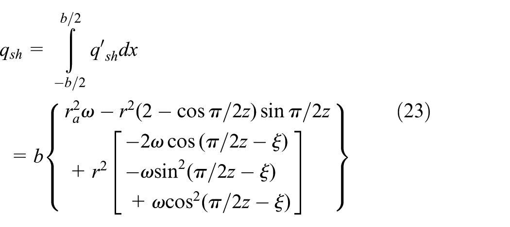
In the formula, the width of the tooth is b.
Furthermore, the pump displacement of each rotation is
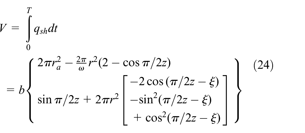
In the formula, T is the time it takes for a gear to turn around a week, T = 2π/ω.
Double circular arc helical gears can be regarded as for be superimposed by countless infinitely thin double circular gears which are continuously turning one phase angle. Flow output characteristics can be obtained by integrating the flow characteristics of double circular arc spur gears, which are infinitely thin from the reference surface at any distance. The angle corresponding to the meshing point of one gear tooth from the base surface is

In the formula, β0 is the helical angle of the double circular arc helical gear and
The instantaneous displacement of the double circular arc helical gear pump whose thickness is dx

The upper formula is a periodic continuous function, and the function is symmetrical in one cycle. So we can get the whole interval functional characteristics by considering the function change in one cycle which is the pulsating characteristics of the output flow.
As shown in Figure 10, the waveform of the tooth width is b advances one phase angle


The output instantaneous displacement of double circular arc helical gear pump.
If

If
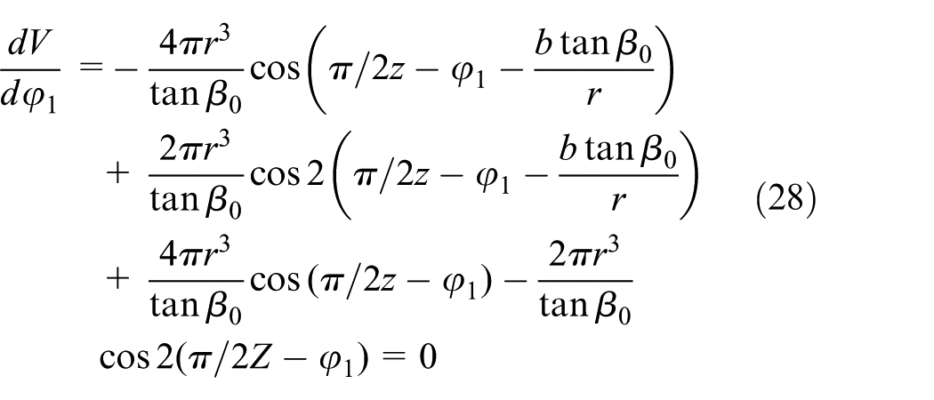
Thus, if

If
When the gear rotation angle turns to the above region, in the double-arc helical gear pump, the first pair of gears have not completely disengaged from the engaging state, and the second pair of gears has been engaged. As shown in Figure 10, the interval ABDC is divided into two parts along the diagonal line BD, and take a straight line EJ with a vertical end-face intersecting line BC at G, where CJ = l, BJ = b – l.
If l = 0,
If l = b,

If
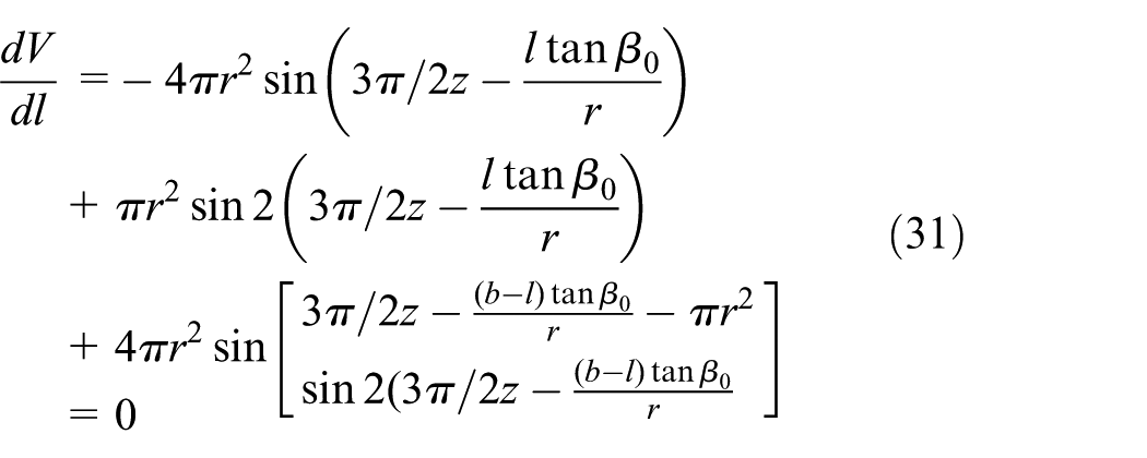
Thus, if
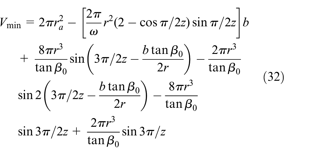
Through the analysis and calculation, the function has only one maximum value and a minimum value in one cycle, which is the maximum and minimum value of the double circular helical gear pump displacement. The fluctuation characteristics of the pump can be obtained by making the difference between the maximum and the minimum displacement.
In the formula, a is gear center distance and Δa is gear center distance error.
By formula (33), it can be seen theoretically that the flow pulsation of double circular helical gear pump tends to 0.
Flow pulsation analysis
In order to verify the correctness of the calculation of flow pulsation theory, assume that the double circular arc helical gear teeth modulus m = 7.5, the number of teeth z = 7, the tooth width b = 45 mm, the pressure angle

A simple model of double circular arc helical gear pump.
The fluid domain of double circular arc helical gear pump is meshed by the pre-processing module (ICEM) in ANSYS (Workbench). Since the gears in the gear pump engage in rotation, that is, the main flow part changes with time, so the unsteady flow (Transient) module is used to describe the flow characteristics. Because the larger size rotation results in larger inverse pressure gradient, the realizable k-epsilon in models nodes is adopted. The definition of the import and export boundary types were pressure-inlet, pressure-outlet, setting the inlet total pressure is 0, the total export pressure of 25 MPa, and setting the way for intensity and viscosity ratio turbulence, turbulence intensity 5% and turbulent viscosity ratio is 5.
The setting of moving mesh adopts smoothing and remeshing. Setting the grid reconstruction methods for local cell and local face, and the reconstruction frequency parameter is 1. When the flow simulation of the gear pump is carried out, only about two gears are engaged and rotated, so the kinematic function file (Profiles) can be used to define the rotation of the two gears. The left and right gears are defined as rigid body movement, and the upper and lower wall of the gear is a deformed region. The deformation shape is plane (setting the region node to move only on that plane).
Setting the surface monitors under the monitors’ node to define the gear pump outlet flow monitor, using the hybrid initialization method of initialization, setting the time step size as 5e–6, 3000 iterations, within 40 iterations, as shown in Figure 12, the flow monitoring curve of the double-arc helical gear pump can be obtained after the calculation. Line 1 and 2 are, respectively, double circular arc helical gear pump flow monitoring curve and involute helical gear pump flow monitoring curve, the Y-axis represents the negative direction, which represents the flow out of the computational domain. As can be seen from the diagram, at the beginning stage, the flow rate of the two gear pumps increases continuously and then fluctuates with time which is the flow pulsation, and the fluctuation interval is the rotation period of the gear pump. The comparison shows that the flow pulsation of the double circular helical gear pump is much smaller than the flow pulsation of the ordinary involute helical gear pump. It is obvious from Figure 12 that the flow pulsation of the double circular helical gear pump is close to 0, which further validates the theoretical analysis of the flow pulsation.

Flow measuring curve of gear pump.
Conclusion
This article proposes two double-arc helical gears as gear pump movement, through theoretical analysis and calculation, which can effectively solve the problem of large flow and pressure pulsation, noise, and serious trapped oil phenomenon of the general involute external gear pump that have been proved.
To further improve the performance of the double-arc helical gear pump, the sine curve is put forward to increase the output displacement and reduce the axial load, thus creating the conditions for the high pressure of the pump.
Using Fluent 3D dynamic mesh technique, by comparing and simulating the flow pulsation of double circular arc helical gear pump and ordinary involute helical gear pump of the same gear parameters, it is concluded that the flow pulsation of the double circular helical gear pump is much smaller than that of the involute helical gear pump.
Based on the meshing principle of gear meshing, the design method of end-tooth profile equation of double circular arc helical gear has been given, which provides a solution for the high performance of gear pumps.
Footnotes
Handling Editor: Shun-Peng Zhu
Declaration of conflicting interests
The author(s) declared no potential conflicts of interest with respect to the research, authorship, and/or publication of this article.
Funding
The author(s) disclosed receipt of the following financial support for the research, authorship, and/or publication of this article: This work was supported by The open topic of State Key Laboratory of Shield Machine and Boring Technology (2014-03).