
Abstract
The pressure-regulating valve can realize the rapid adjustment and precise controlling of operating pressure and Mach number, to stabilize the flow field and avoid the test interference such as the air source loss or the unstable flow. This paper takes the design and optimization of pressure-regulating valve in trisonic intermittent wind tunnel as the research object to investigate its special pressure-regulating characteristic and performance in the wind tunnel. According to the requirement of the wind tunnel, the annular-gap type pressure-regulating valve is selected to match its wide adjustment range of operating parameter, high regulation accuracy, and low running resistance. The design and optimization of the pressure-regulating valve are carried out, including aerodynamic and structural design, analysis on pressure regulation characteristics, kinematics analysis, flow field analysis, vibration analysis, and structure optimization. The design and selection of some important components are carried out based on the pneumatic design and performance requirements. The pressure regulation characteristics of the pressure regulating valve are discussed and the affecting factors of the irregular flow are analyzed and evaluated by numerical simulation. The final structure of the pressure-regulating valve is determined and the test results perform well with prediction of characteristic curve.
Keywords
Introduction
The wind tunnel experiment is the basic requirement for the aerodynamic design of aircraft and spacecraft, the quality of flow field in the wind tunnel directly affects the authenticity of the test result. Wind tunnel is a kind of ground equipment, based on the relativity, and similarity principle of motion, which produces controllable airflow by power device in a specific pipe structure to carries out various aerodynamic tests on aircraft or objects in the airflow. The pressurized air is stored in the storage tanks, by using tube and valve, the high pressure air is directly delivered into the wind tunnel. The test environment needs to be established and regulated in a short time by a valve. Adopting this drive system of wind tunnel is called intermittent wind tunnel. It is widely applied in transonic, supersonic, and hypersonic wind tunnel. Among many air flow parameters, the most important parameters are the total pressure P0 in the operation of the wind tunnel and the Mach number (Ma) of the test airflow Ma, their control precision are the criteria to judge the quality of the flow field in wind tunnel. During the intermittent wind tunnel operating, the quality of the flow field deteriorates the test result. It has a large deviation with its actual value as the pressure of the air source changes, leading to the potentially fatal hazard in the advanced design and safe of the aircraft. 1 Wind tunnel with poor quality of flow field not only fails to provide accurate test conditions, but also hinders the development in aircraft. To this end, the quality of the flow field is taken as the criterion in the design, construction and application of wind tunnel. 2 In the past, in order to obtain different test conditions and flow fields, a large number of intermittent wind tunnels with single functions and poor accuracy were constructed to form a wind tunnel test group, to meet the aerodynamic tests of various states for the aircraft. 3 This method costs huge investment and has low efficiency. In recent years, the development of modernization aviation, the aircraft has gradually transits from the previous low speed, low altitude and large size to super-hypersonic speed, refinement, and high accuracy. This goal requires the construction of a high-performance intermittent wind tunnel that can achieve the high quality of flow field and the wide range of operating parameter to improve the test efficiency and data accuracy. 4 During the operation of the intermittent wind tunnel, pressure drop and pressure pulsation will generate due to the consumption of air source, which causes the fluctuations of the airflow inside the wind tunnel. Consequently, it affects the quality of the flow field and test accuracy, even causing internal structure damage and equipment operation.
In order to ensure the stable operation and test capabilities of the wind tunnel, a special valve, called wind tunnel pressure-regulating valve, needs to be installed on the air intake line of the intermittent-stroke wind tunnel to realize the airflow regulation and controlling. In the trisonic intermittent wind tunnel, the pressure regulating valve is arranged at the air inlet of the wind tunnel, to connect the air source and the wind tunnel hole. In the operating process of wind tunnel, the pressure of air source will gradually decline and fluctuate unsteadily. The opening of the pressure regulating valve is adjusted through the control system to control the air intake of the tunnel, in order to ensure that the pressure in flow field is stable within a certain operating range and maintain the normal operation of the wind tunnel. Moreover, according to different test needs, the flow field in the wind tunnel can also be changed through the implementation of the regulating valve to meet the requirements of working conditions. Therefore, the pressure regulating valve is the core equipment of the total pressure control in the wind tunnel. This paper focuses on the structural design and operation characteristics of the pressure regulating valve and the related factors affecting the operation of the valve. From the view of fluid mechanics and wind tunnel operation experience, among the airflow parameters, the main controlling parameters for the flow field in the wind tunnel are the total operating pressure and the Mach number Ma.5–7 According to the requirements of the test, the air flows from the air source into the tunnel through the pressure-regulating valve which is adjusted to achieve the adjustment of the Mach number and the total operating pressure. 8 In addition, the pressure-regulating valve also has a quick responding function. If an accident occurs, the valve can quickly respond to protect the wind tunnel equipment and prevent the damaging to the workers.
There are relatively few public literatures on wind tunnel pressure-regulating valves, but a lot of research works was carried out in the valve with similar pressure regulation and flowing control functions. Asim et al. 9 studied the influence of the structural characteristics of the flow control valve on the flow field and analyzed the complicated flow paths, the results shows that their behaviors are formed by different structures. Asim et al. 10 designed and studied the control valve for the energy system based on computational fluid dynamics, the mechanical performance analysis of the control valve under complicated working conditions was conducted. Sun et al. 11 studied the effect of surface roughness on the flow coefficient of an eccentric butterfly valve and numerically analyzed the effect of airflow friction on the flow coefficient of each valve opening. They found that the roughness significantly increases the friction pressure drop. Lisowski and Grzegorz 12 studied the opening shape of the flow control valve and the flow characteristics under different openings through experiments. It obtains that the spool with a triangular opening can extends the flow adjustment range. Charlton et al. 13 studied the influence of the channel surface roughness flow on the performance of the control valve from the aspect of complicated manufacturing process. The result provides an important reference for the manufacture of the control valve. Beune et al. 14 studied the opening characteristics of high-pressure safety valves and analyzed the influence of the structure on the flow field in the process of valve opening through fluid-structure interaction, which provided a reference for the optimal design of the structure.
The pressure regulation characteristics and stability of the pressure-regulating valve is the key to the high level of testing capability. 15 Therefore, the design and development of the pressure-regulating valve are very important for the construction and operation of the whole wind tunnel system. As mentioned above, the design and characteristics of the wind tunnel pressure-regulating valve have been studied by simulations and experiments. Most researchers focused on the valve configuration scheme, operation control method and operation feature, etc., based on the use of pressure regulators in the past. However, few works have been carried out on the structural design and optimization, manufacturing, dynamic responding, performance testing, etc., of the pressure-regulating valve in intermittent wind tunnel. In this paper, based on the design and construction of a new transonic intermittent wind tunnel, the design and optimization of the pressure-regulating valve are carried out from the aspects of aerodynamic shape design, theoretical calculation and analysis, structural design and optimization, etc. The development method of pressure-regulating valve provides a reference for the similar valve design and structural optimization in the future.
Pneumatic and structure designs
The pressure-regulating valve is configured in trisonic intermittent wind tunnel. The wind tunnel is a semi-reflux type with a horizontal layout. The central axis size is about 96.5 m × 19 m (length × width), the maximum height is about 22.5 m and the total structure weight is about 2200 t. Figure 1 shows the three-dimensional structure diagram and pipeline layout of the wind tunnel. The wind tunnel mainly includes air source system, pipeline and valve system, wind tunnel main structure, measurement system, monitoring and controlling system and auxiliary facilities. Among them, the pressure-regulating valve belongs to the pipeline valve system of the wind tunnels, which controls the start and stops of the wind tunnel and adjusts the operating parameters of the wind tunnel.

Diagram for the three-dimensional structure and pipeline layout of the wind tunnel: (a) intermittent transonic wind tunnel and (b) structure sketch of valve and piping system.
According to the requirements of design and construction, the main structural parameters and operational requirements of the wind tunnel are listed as:
Cross-section size of wind tunnel test section: 1.2 m × 1.2 m;
Inner diameter in settling chamber: Φ4.7 m;
Working air source: Medium pressure air source system, Pg ≤ 2.5 MPa;
Working temperature: Room temperature;
Working pressure in settling chamber: P0 = 0.6 × 10⁵–12 × 105 Pa;
Flow rate in test section: G = 260–1550 kg/s;
Test range of Mach number: Ma = 0.3–4.25;
Control accuracy of wind tunnel total pressure: |ΔP0/P0| ≤ 0.2%;
Control accuracy of Mach number: |ΔM| ≤ 0.002.
The airflow pressure in the settling chamber is taken as the total operating pressure of the wind tunnel. The controlling precisions of the total pressure and the Mach number are the final goals of the design and optimization for the pressure-regulating valve. 16
Pneumatic design
The annular-gap type pressure-regulating valve is selected because it has the characteristics of high sensitivity, fast starting speed, wide pressure regulation range, etc. Most important is that it can realize the linear pressure regulation and preset the pressure regulation range, which is very suitable for the large-size and high-performance of the trisonic intermittent wind tunnel. Figure 2 shows the two-dimensional schematic diagram of the pressure-regulating valve. According to the working principle of wind tunnel pressure-regulating valve and pneumatic design principle, the characteristic parameters for the important aerodynamic size are determined, including the valve diameter D, total stroke of pressure-regulating Smax, valve opening

Two-dimensional schematic diagram of pressure-regulating valve.
Valve diameter D.
In order to make the valve which has a good adjustment characteristics and a reasonable pressure loss along the tube, based on the maximum working pressure of the air source, the airflow velocity coefficient λ of the pipeline behind the pressure-regulating valve is determined in the range of 0.05–0.5. The diameter of the pressure-regulating valve is determined to be D = 1300 mm in the basic of the operating pressure, flow rate, working pressure of air source and air flowing velocity behind the valve, etc.
Total stroke of pressure-regulating Smax
Pressure-regulating stroke S is the motion stroke of the spool matching the pressure-regulating profile to regulate the pressure behind the valve, so the full stroke of the spool can realize the pressure regulation which is the total valve pressure-regulating stroke Smax. Smax is generally 0.15–0.7 times the diameter of the pipe behind the valve based on the experience of pressure-regulating valve. For wind tunnel with large size and high flow rate, in order to coordinate the delay effect of pressure regulation and pressure stability, Smax can be appropriately shortened by 0.3–0.5 times the diameter of the pipe behind the valve. The control stroke of the pressure-regulating valve Smax = 600 mm (0.46 D) is finally determined according to the inner diameter of the settling chamber and the distance between the pressure-regulating valve and the settling chamber.
Valve opening
Valve opening
Pressure-regulating surface design
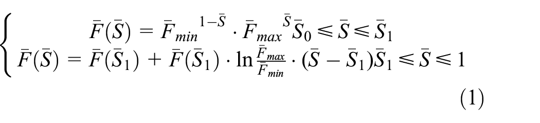
The flow channel in the pressure regulating valve is mostly in the form of a symmetrical revolution. The flow channel is projected along the symmetry plane passing the central axis to obtain a two-dimensional curve, called a surface curve. The annular flow channel formed by this curve is the key to realize the pressure-regulating characteristics. The pressure-regulating profile design is to carry out the design of the surface curve. 18 In order to ensure the relative displacement of the valve core and the relative change of the pressure behind the valve, the surface curve of the pressure valve is often designed as an exponential characteristic curve which is basically linear. The valve control system has a simple exponential relationship to precisely control the airflow in the valve surface flow cavity. The characteristic curve of the regulator valve surface is composed of three sections. Initial segment: starting from the valve closed position (starting point of the pressure-regulating stroke) until the valve reaching the minimum opening with straight line. Middle segment: the straight-line transits to the exponential characteristic curve in the middle segment and the exponential curve extend to 80% of the pressure-regulating stroke. The latter section then transits smoothly in a straight line to the end of the pressure-regulating stroke. The middle segment is the main pressure-regulating zone of the valve, which is the most sensitive and controllable zone of pressure-regulating characteristics. A mathematical model of pressure-regulating profile is established, as shown in Figure 3.

Pressure-regulating performance geometric.
The surface curve can be regarded as the relationship curve between the flow area and the pressure-regulating stroke:
where, D = 1300 mm,

The geometric pressure regulation characteristic curve of the relationship between valve opening and valve core displacement is given as Figure 4.

Geometric characteristic of pressure-regulating valve.
The geometric pressure regulation characteristic curve is obtained based on geometric characteristic of pressure-regulating valve:

The surface curve coordinate equation can be got by combining equations (2) and (3):


The X–Y profile coordinate curve can be draw by solving equation (4), as shown in Figure 5. This curve serves as an important input condition for the design of the pressure-regulating valve structure, and the corresponding x and y coordinates of the curve are the parameters of the pressure-regulating profile.
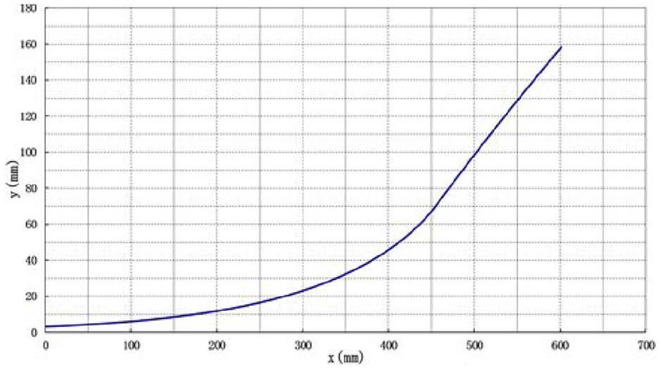
Profile curve of valve.
Structure design
Based on the requirement of wind tunnel performance and aerodynamic scheme, the structural design, and overall technical requirements of the pressure-regulating valve are given as:
The layout of each structure is reasonable to meet the load bearing requirements.
The design of the valve’s motion mechanism is reasonable and its operation is smooth without jams, hysteresis, etc.
The opening load of the pressure-regulating valve should be as small as possible and the pneumatic load acting on the valve core should toward the closing direction of the valve.
There is no gas leakage when the valve is running and after the valve is closed.
The spool movement stroke requires real-time and accurate measurement, the measurement error less than 0.2 mm.
The maximum deviation between the spool movement axis and the profile axis is less than 0.5 mm.
Except for the surface, there should be no diffusion of airflow in the valve channel inside and the equivalent diffusion angle of the flow channel inside the valve is less than 10°.
The structures in the valve should far away from the airflow as possible. The supporting members arranged in the airflow should be rectified. The blockage of the flow passage should be less than 15%.
The load bearing of each structure is less than the allowable stress of the material.
Figure 6 gives the schematic diagram of valve body.

The schematic diagram of valve body: (a) valve body and (b) schematic diagram of two-dimensions structure.
Wall thickness of internal pressure cylinder can be obtained

The flow area of valve inlet and outlet are calculated by


Table 1 shows the specific performance of valves.
Design indices of pressure-regulating valve.
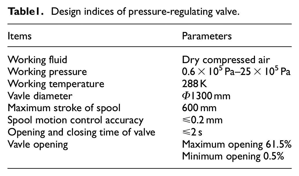
Figure 7 shows the schematic diagram of valve body. The structural design requires the pressure-regulating valve D1–D0 > D2–D0. It has been determined above that the maximum outer edge diameter of the valve core D = 1300 mm, so the diameter of the front boss is D1 = 1300 mm. It needs to meet D1 > D2 to consider the installation of the rear seal and the operating space of the valve spool according to the structure size of the valve body. The initial value of the settling diameter is D2 = 1280 mm and the valve spool cylinder structure is D0 = 1260 mm (including wall thickness). The valve spool and the valve body are pressure-bearing shells for easy production together and the valve spool wall thickness is 50 mm. The length of the spool structure is determined according to the empirical correlation L = (0.6–1.5)D0. Combining the total stroke of the pressure regulation, the abscissa value of the profile, the structural installation dimensions of the guiding device and the driving mechanism, the length of the spool is initially determined to be L = 760 mm. The total length of the valve body is preliminarily determined 4100 mm (including the length of the pipe butt flange) to meet the requirements of the valve spool length, the total stroke of the valve core, the mechanism stroke and the diffusion angle of the flow channel.

The schematic diagram of valve spool: (a) three-dimension structure of valve spool and (b) two-dimensional diagram of valve spool.
Results and discussion
Analysis and calculation of pressure regulation characteristics
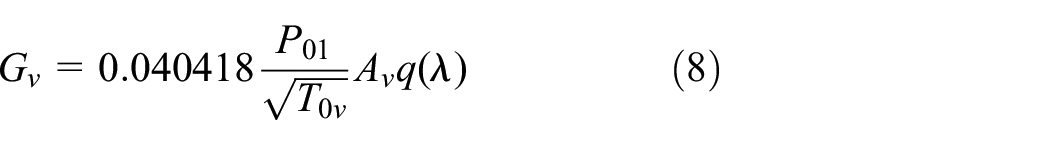
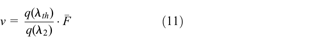
The flow rate is deduced by

The flow rate at any valve opening is given by
When the airflow reaches the sound speed through the pressure-regulating surface, it is called the critical state (q(λ) = 1). The pressure-regulating valve is in a critical state during operation.

It is approximately regarded that the pressure in front of the valve equals to the air source pressure (P01 = Pg) due to the large volume of the air source in the wind tunnel. It is assumed that there is no change in temperature (T0v = T0) and energy loss.
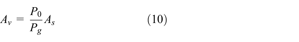
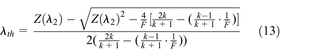
The calculation of pressure-regulating characteristic includes pressure opening characteristic and airflow velocity characteristic. The pressure-regulating surface and the valve spool in the pressure-regulating valve form a throttling throat. Assuming the airflow isenthalpy, the following equation can be derived
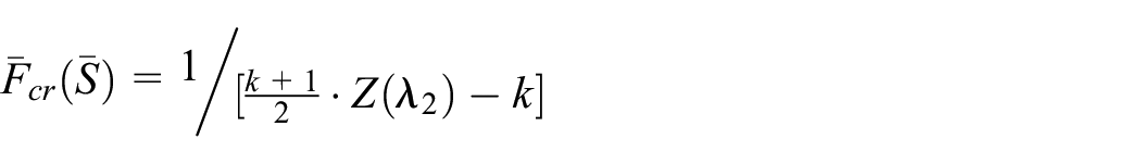
V presents the pressure recovery coefficient


As
As
Table 2 shows the operating parameters of the pressure-regulating valve when the wind tunnel operates at various typical Mach Numbers according to the wind tunnel operating conditions.
Operation parameter of valve for Mach numbers.
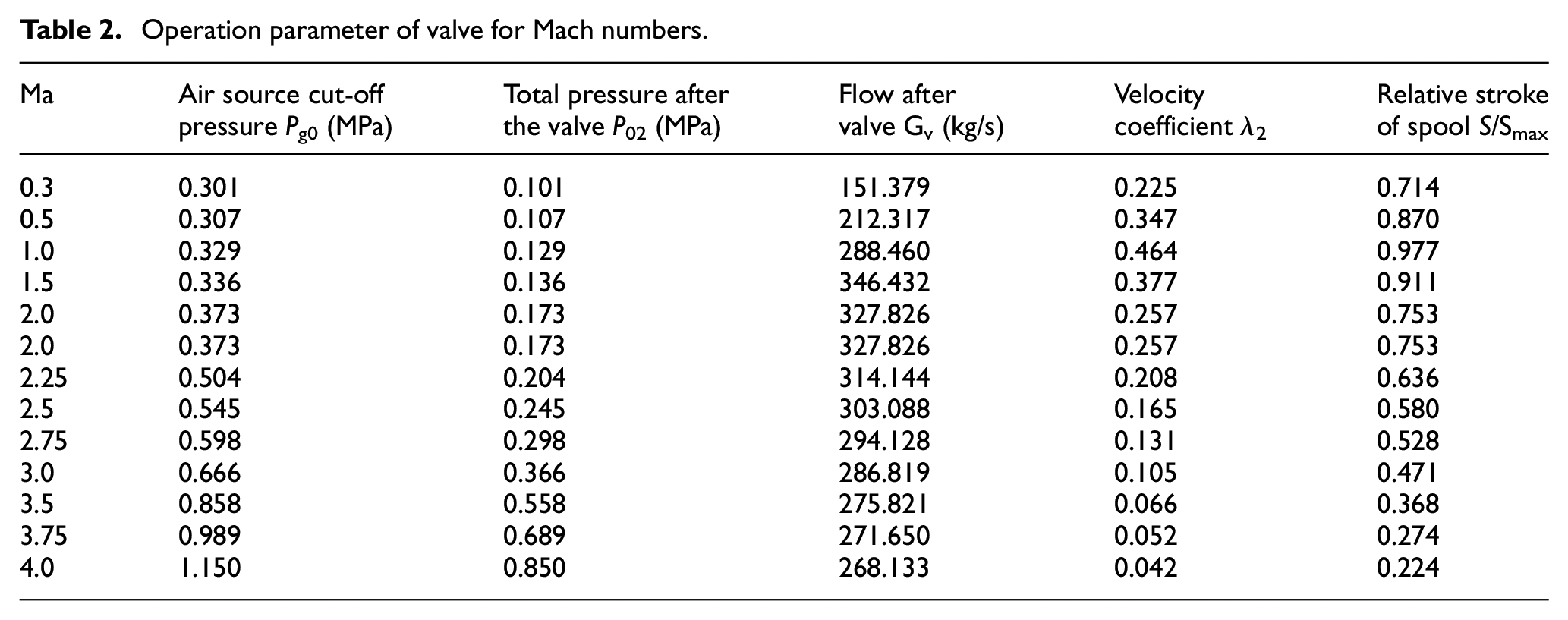
The adjustment characteristic curve can be obtained by taking the valve parameters as known conditions and solving the above joint-equations. As shown in Figure 8, the pressure-regulating characteristic curve and pressure-regulating speed characteristic curve at different Mach numbers are respectively given. Figure 8 reflects that the theoretical pressure-regulating characteristic curve of the pressure-regulating valve is approximately linear when the Mach number is between 0.3 and 4.5. The airflow velocity coefficient λ after the valve gradually decreases and the overall pressure regulation performance curve shifts to the left as the Mach number of the test flow field increases. At the same spool position, the pressure ratio between the front and back of the valve increases gradually. It can be seen from Figure 8(a), at the same Mach number, the slopes of the front and back sections of the curve are small that the movement of the spool is insensitive to this area and the performance of the valve regulator. The slope in the middle of the curve is large and it is the main adjustment area of pressure.

Pressure-regulating performance curve: (a) Mach number and (b) speed characteristic.
Kinematics analysis
The dynamic analysis of the pressure-regulating valve is performed to obtain the spool movement, load parameters and optimize the structural scheme design. A kinematics model of the valve spool and other components are established during the operation, as shown in Figure 9(b). A is the fixed point of the cylinder, B is the connection point between the cylinder and the spool, C is the one-way sliding of the guide rod, M is the starting point of the spool movement, M′ is the point of the spool movement, and N is the valve. The maximum stroke end of the core, O is the origin, and the airflow axis is the X axis to establish an X–Y coordinate system. During the valve opening process, the cylinder link point B moves to B′, driving the spool to move from point O to point M, and △S is the movement stroke of the spool.

Motion geometry: (a) motion model and (b) spool mechanical model.
Displacement of spool motion is expressed as

Spool acceleration phase motion displacement S1

Movement displacement of spool in uniform velocity stage S2

Spool deceleration phase movement displacement S3
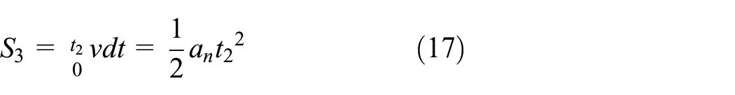
If

If

The spool structure is simplified as a mass point for force analysis based on the kinematics model, as shown in Figure 9(b). The force of the spool structure can be expressed as


Among them,
The spool is uniformly accelerated and uniformly decelerated, the acceleration and deceleration control time is the same in usual.
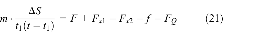
The driving load of the spool can be derived through the spool travel and movement time
The following assumptions are made for the motion system when modeling to facilitate the simulation calculation,
All structures are absolute rigid bodies and the components is no elastic deformation after being loaded;
There is no gap between the movement pair and the connecting parts and all the components are in close contact;
Only the friction coefficient of the guiding system is considered, and the frictional resistance generated by the structure and airflow is ignored.
Boundary layer
To avoid the interference in the movement of various parts and affecting the analysis results, some constraints are added to each link. In addition to the direction of movement, the valve spool and guide rod restrict the remaining degrees of freedom, and the valve body, guide rail support, and other structures are set to be fixed.
The total stroke of the spool full opening or full closed one-way movement is 600 mm, and the total running time is 2 s. The acceleration and deceleration movement time is 10% of the total movement time. The friction coefficient of the guide rail slider is 0.002, the friction coefficient of the guide rod is 0.15, all the components are made of steel, and the acceleration of gravity is 9.8 m/s2.
Combined the solution of the motion equation, the velocity-time function is established as the spool motion function. The two extreme conditions of pressure-regulating valve full opening and full closed are solved to obtain the movement parameters of the valve spool and to extract the driving load of the connecting rod. When the valve is full opening, the initial spool is in the closed position and the initial speed is zero. The end faces of the front and rear bosses of the valve core are subjected to gas pressure, which is applied at the maximum gas source pressure of 2.5 × 10⁶ Pa. Figure 10 shows the curve of displacement, velocity, and driving load of the spool. Table 3 shows the specific simulation results. The results show that the valve spool displacement and speed are equal when the pressure-regulating valve is opened and closed, the maximum operating speed is 0.334 m/s and the peak acceleration is 0.251 m/s2. Due to the opposite direction of opening and closing movement, the spool has different forces and drive loads. The spool has the largest drive load during the full opening process, with the maximum drive load being 117.4 kN.

Extreme condition simulation: (a) spool’s displacement of opening, (b) spool’s displacement of closing, (c) spool’s speed of opening, (d) spool’s speed of closing, (e) driving force of opening, and (f) driving force of closing.
Motion simulation results of valve.

The front and rear ends of the spool are designed as a boss structure. The size of the front boss is determined according to aerodynamic calculations D1 = 1300 mm, the initial value of the rear boss is D2 = 1280 mm. The size of the front and the rear bosses of the spool are determined through the axial load of spool structure and the driving load. In order to obtain the optimal structure, under the fixed working conditions and parameters, only changing the size of the boss after the spool, the movement analysis is performed to get the respective driving load value. The size of the spool rear boss is D2 = 1270, 1280, 1290 mm for motion simulation calculation, the load curve is shown in Figure 11 and the specific data is shown in Table 4. It can be seen from the results that when the diameter of the spool rear boss is D2 = 1290 mm that the driving force is the smallest. The driving force is the largest as D2 = 1270 mm. It is known that the diameter of the front boss is D1 = 1300 mm. The smaller in the difference between D1 and D2, the smaller in the driving force is required for movement. However, the difference between D1 and D2 is not better as small as possible, because the size of the front and rear bosses is the same. If the structure movement gap is too small, the structure will be scratched and blocked during the movement, which will damage the valve body.

The driving load of valve on opening and closing: (a) the driving load on opening (D2 = 1290 mm), (b) the driving load on closing (D2 = 1290 mm), (c) the driving load on opening (D2 = 1280 mm), (d) the driving load on opening (D2 = 1280 mm), (e) the driving load on opening (D2 = 1270 mm), and (f) the driving load on closing (D2 = 1270 mm).
Motion simulation result of different valve core.

Flow field analysis in valve
Grid independence
Figure 12 shows the three-dimensional flow field model of pressure-regulating valve and mesh generation. The grid uses unstructured tetrahedral elements. The model is divided into approximately 3.83 million meshes. In order to improve the accuracy of the calculation, local meshes are refined for the flow path of the pressure-regulating valve. The end of the valve spool, the valve outlet and the shrinking wall and the global mesh quality are optimized. The RNG k–ε model is adopted for flow field analysis to solve the complicated flow channel in the pressure-regulating valve, due to the large pressure difference in the front and rear, vortex, jet and other complex flow phenomena and high-speed fluid separation in the valve. 19 The pressure inlet and pressure outlet as inlet and outlet boundary conditions are adopted, the inlet and outlet temperature are set as 288.15 and 280.15 K, respectively. The incompressible fluid is selected. The axial and vertical interfaces of the model are set to the condition of symmetry. The fluid-wall is set to the condition of no-slip wall.

The validation in grid independence.
For steady-state numerical simulation, the grids independence is performed to ensure the reliability of the obtained results. The results in the variation of pressure behind the valve are paid more attention, therefore, the pressure value in the cross-section at the outlet of the pressure regulating valve at the position X = 16,000 mm are extracted to verify the mesh independence. Calculation conditions: the displacement of valve core in the pressure regulating valve is △S = 300 mm (the valve opening is 50%); the wind tunnel running Mach number Ma = 0.6; the inlet pressure is 0.9 × 10⁵ Pa, and the outlet pressure is 0.6 × 10⁵ Pa. In this cross section, 3 points are selected, and the coordinates of each point are (16000, 450, 0), (16000, 0, 0) and (16,000, −450, 0), respectively. The calculation results are shown in Table 1.
As shown in Figure 12, when the number of grids changes from 3.2 million to 4.4 million, the pressure at each point changes very little with the increase of the number of grids. Considering the calculation cost and accuracy, 3.83 million grids are selected for calculation and analysis (Figure 13).

Flow field simulation: (a) three-dimensional flow field model of pressure-regulating valve and (b) mesh generation.
Results analysis
Figure 14 shows the distribution of Mach number in the flow field of the valve under different working conditions. It can be seen from the Figure 14 that the maximum Mach number of the flow field in the valve is behind the minimum section formed by the valve spool and the profile of flow channel. The flow area of this region increases with the increase of the valve opening, which confirms the aerodynamic law. The flow rate in front of the valve is relatively low and the Mach number of the airflow increases sharply after passing the flow channel. The flow rate behind the valve gradually decreases but it is higher than that before the valve. The reason is that the flow path first contracts and then expands. The throttling throat is formed and the high-speed jet effect is locally produced. For the flow velocity behind the valve, the change gradually tends to be flat, which is caused by the sudden diffusion of the flow path behind the valve.

The Mach number distribution of internal flow at different working condition: (a) Ma = 0.6,
Table 5 shows the maximum Mach number under different operating conditions. The maximum Mach number of flow field is related to the operation condition of wind tunnel. When the spool opening is the same and the operation Mach number in the wind tunnel is Ma = 0.6, the Mach number in the flow field is the highest because the inlet/outlet pressure ratio is the lowest. At the same Mach number running in the wind tunnel, the maximum Mach number of the valve spool displacement ΔS = 450 mm is greater than the maximum Mach number in the flow field of ΔS = 300 mm, because the airflow in the valve is related to the flow area. A larger flow area has a better flow acceleration and it has a corresponding faster flow rate.
The maximum Mach number of flow field analysis.

Figure 15 shows the streamline and pressure distribution of the flow field in the valve. It can be seen from the Figure 15 that the internal flow state of the pressure-regulating valve is basically the same under different working conditions. When the valve is running, the pressure in front of the valve is relatively large and the maximum pressure is distributed in the head of the valve body, which is the same as the pressure of the air source. The pressure decreases and stabilizes after passing through the pressure-regulating surface in the flow channel. Under the same operating conditions and air source conditions, the valve spool is at different openings and the airflow pressure values after the valve are different. It is verified that the pressure-regulating valve can adjust the pressure after the valve by changing the opening of the profile flow passage through the movement of the valve spool.

The pressure distribution of internal flow at different working condition: (a) Ma = 0.6,
The valve spool, guiding the support rod and the ribs supporting the valve body are all in the vortex area. The repeated action of the asymmetric vortex may increase the aerodynamic load and affect the valve operation. Table 6 shows the load in the X-direction of the valve spool, support ribs and guide rods in the vortex area. It can be found from the table that, under the same working condition, the valve is at different opening degrees and the force of each component changes significantly. When the spool displacement changes from ΔS = 300 mm to ΔS = 450 mm, the force on the supporting ribs increases. When the spool opening is the same, the force on the spool and the guiding rod are relatively large under different operating conditions, but the force in X-direction is opposite. The reason is that the valve core is located in the throat contraction position, where the pressure is high and the airflow is impacted by the airflow. The guiding rod is always in the core area of the vortex, the load suddenly changes thus that the turbulence may produce a counterforce.
Flow impact load of structure at different working condition.

The vortex may be caused by the plugging cone and cavity formed by the inner shell of the valve and the valve core, as well as the disturbance of the airflow caused by the guide rod and the rib supporting the valve body. The generated vortex under different valve openings is different. Therefore, the opening of the valve increases, the area and intensity of the vortex decreases. Figure 16 shows the influence curve of the boss structure on the front edge of the spool on the aerodynamic load in the vortex area. The result reflects the larger the inverse step difference of the front boss of the reaction spool and the larger the aerodynamic load in the vortex area, indicating the more severe disturbance of the air flow. The smaller in the step difference, the smaller in the aerodynamic load and the smaller in the impact on valve operation. When designing the spool structure, it is necessary to reduce the size of the structural step difference, minimize the interference of the structure on the flow field and avoid irregular airflow disturbances affecting the valve operation. In addition, full consideration should be given to factors such as drive load and airflow pressure load to be reasonable structure size.

The curve about spool and aerodynamic load.
Vibration analysis and structure optimization
In order to avoid resonance, the spool structure should be analyzed and optimized specifically to improve the safety and reliability of equipment operation. 20 The natural frequency calculation equation is

If the natural frequency of the structure is reduced, the stiffness of the structure will be reduced and the stability of the structure will be affected, which is not conducive to the bearing pressure of the valve. 21 Therefore, for pressure-regulating valves with high load requirements, the natural frequency of the structure should be increased. 22 On the basis of not affecting the manufacturing and installation space, the valve core and the guide rail support are optimized respectively. The specific structural improvements are as follows:
Improving the rigidity of the spool itself;
Increasing the stiffness of the external support.
According to the above improvement method, the structure design is optimized. The valve spool and the guide rail support before and after the improvement are shown in Figures 17 and 18.

Optimized structure design of valve spool: (a) before structural improvement and (b) after structural improvement.

Optimized structure design of guide seat: (a) cross bracing and (b) tic-tac-toe support.
The effects of the two optimization methods are examined and three schemes are compared. Among them, the first option is to improve the structure of the moving valve core; the second option is to improve the structure of the guide rail support; the third option is to optimize and improve both the valve core and the guide rail support. The analysis of structural modal analysis on the three schemes is carried out and the natural frequency of the structures is calculated respectively, and the most effective scheme is selected by comparing with the natural frequency of the structures before improvement. Figure 19 shows the natural frequency comparison of the first 10 modes of the three structural optimization schemes. It can be seen from the figure that the three structural improvement schemes have improved the structural mode.
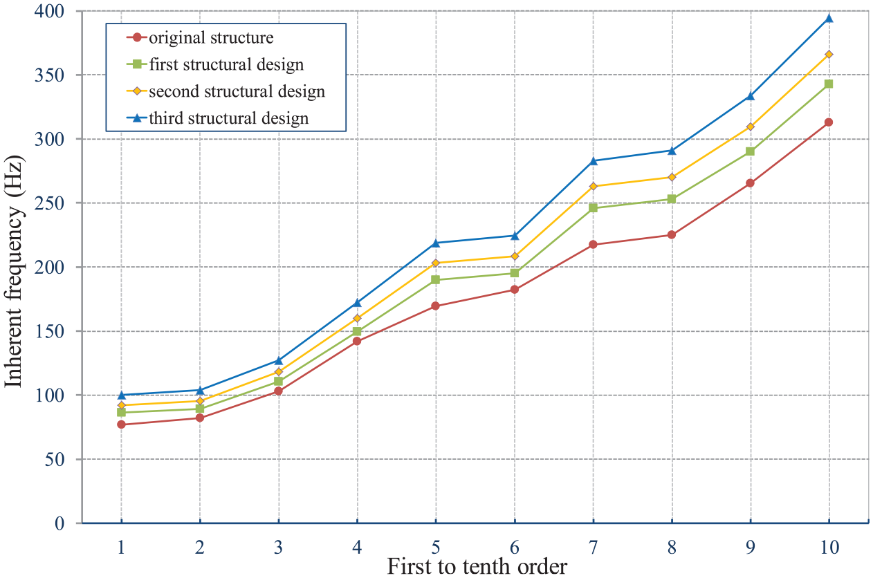
Comparison of results before and after optimized structures.
Table 7 shows the natural frequency values of the first 10 modes of each party and the difference between them and the natural frequency of the structure before the improvement.
First ten natural frequencies of different optimized structures.

The following conclusions can be drawn by selecting different schemes for the pressure-regulating valve and comparing the modal calculation results of each structure:
Strengthening structural support or increasing plate thickness and quality can increase structural rigidity and improve the natural frequency of the structure. The natural frequency value of each order of the structure is outside the excitation frequency range and the valve is not easy to resonate due to the action of air flow during operation, which realizes the improvement of the inherent characteristics of the valve structure;
The natural frequency of each order of the improved structure is improved compared with the structure before optimization. Case 3 has the largest increase in natural frequency, case 1 has the smallest increase, indicating that the optimization effect of case 3 is the best;
The two degree natural frequency of the structure in case 2 is larger than that of case 1, it indicates that in terms of increasing the natural frequency of moving parts, the effect of increasing the rigidity of the external support structure is better than increasing the structural rigidity of the moving parts itself, so increasing the binding force on the moving parts is beneficial to improve its operational stability.
Conclusions
In this paper, a pressure-regulating valve is designed in the basic of the aerodynamic and structural design, analysis on pressure regulation characteristics, kinematics analysis, flow field simulation, vibration analysis, and structure optimization. Some general conclusions are summarized as follows:
The calculation method of the pressure-regulating characteristic curve is given according to the performance requirements of the wind tunnel. The analysis results reflect that, at the same Mach number, the slopes of the front and the back sections of the pressure-regulating characteristic curve are small. It means that the movement of the spool is insensitive to this zone and the performance of the valve regulator. The slope in the middle of the curve is large and it is the main pressure adjustment zone.
The decrease of the difference between D1–D2 induces the reduction in the driving force required for movement. A very small difference is not always beneficial because the size of the front and the rear bosses are the same, which cause the structure movement gap too small, resulting in the structure scratch and block during movement, consequently, damaging the valve body.
The pressure changes obviously as the air flow through the pressure-regulating valve. Different valve openings induce the different post-valve pressures under the same flow rate conditions. The results show that the pressure-regulating valve has post-valve pressure regulation characteristics. When the wind tunnel is operating at different Mach numbers, the flow field behind the valve shows obvious unsteady characteristics. The uneven flow field may be an important reason for valve vibration and structural damage.
Strengthening the supporting structural or increasing plate thickness and quality can increase the structural rigidity and improve the natural frequency. The natural frequency value of each order is outside the excitation frequency range, and the valve is not easy to resonate due to the action of air flow during operation, which realizes the improvement of the inherent characteristics of the valve structure.
Footnotes
Handling Editor: James Baldwin
Declaration of conflicting interests
The author(s) declared no potential conflicts of interest with respect to the research, authorship, and/or publication of this article.
Funding
The author(s) disclosed receipt of the following financial support for the research, authorship, and/or publication of this article: The authors would like to acknowledge the support by the National Natural Science Foundation of China (No. 51905204), the Hubei Provincial Natural Science Foundation of China (No. 2018CFB227), the Fundamental Research Funds for the Central Universities (No. 2662017QD003), and State Key Laboratory of Mechanical Transmission, Chongqing University.