
Abstract
Compared with traditional rigid gripper with joint-linkage structure, novel soft robotic gripper gives rise to continuous concern for the advantages of no-damage grasping, convenient manufacture, easy control, and low cost. In this study, we design and built two kinds of soft robotic grippers with four fiber-reinforced soft actuators which are distributed in circular and rectangle shapes for single and twin contacts grasping. A novel hybrid valve pneumatic control scheme combining proportional and solenoid valves is proposed. Also, a mode controllable hybrid valve pressure control method is proposed to adjust internal pressure of soft robotic grippers to adapt to different grasping tasks. The experiment results verify that the performances of hybrid valve outperform those of individual proportional valve or solenoid valve in the aspects of response time and steady-state accuracy. The hybrid valve has wide range of pressure regulation, result in that the soft robotic grippers are qualified to grasp various objects with different shapes, sizes, and weights.
Introduction
The robotic gripper is one of the key parts of manipulation robots. Traditional robotic grippers are rigid joint-linkage structure, result in that there exists rigid contract between robotic grippers and grasped objects. 1,2 Hence, there are enormous challenges of sensing and control to perform precise and no-damage grasping. In recent years, with the development of soft robotics, more and more scientists attempt to realize flexible grasping with the aid of soft robotic grippers (SRGs), which are made of soft material for instance silicon rubber. 3 –7 Ilievski et al. 8 fabricate a starfish-like SRG with six pneumatically driven soft actuators, which has simple structure but is not powerful enough to grasp heavier objects. Li et al. 9 manufacture a more complex soft gripper with a pack of particles, and when inflated, the larger squeezing pressure of particle jamming would promote the stiffness, so that this soft gripper can be applied to more occasions. These SRGs overcome the limitation of rigid contract and show great superiority on many aspects of safety, 10,11 lightweight, low material costs, uncomplicated manufacture, 2,8,12,13 and sample control, 14 –16 and the most valuable effect is that no-damage grasp becomes more easily. 17 –20 However, these SRGs focus on innovational structures, consider less admirable pneumatic control method. 21 –24
Currently, the pneumatic control schemes for SRGs concentrate on individual proportional valve and individual solenoid valve. The proportional valve is convenient to stabilize dynamic air pressure and achieves excellent linearity between control command and output pressure. 16,25 The proportional valve is flexible but sacrifices fast respond performance, because of that there needs time to process pressure adjustment. The solenoid valve is normally used as switch to input and output air and also adjusts output pressure depending on pulse-width modulation (PWM) signal. 26 –28 Thus, the solenoid valve is excellent on the aspect of response time, but inappropriate output parameters still damage the object and SRG, despite that rude touch is decreased thanking to flexible performance of SRG. Therefore, it is necessary to find a better scheme to perform high-performance pneumatic adjustment. Hybrid valve pneumatic control (HVPC) scheme may be a good option.
Therefore, this article carries out research from two aspects: how to design and implement SRG and how to design pneumatic control scheme with hybrid valve for SRG. Firstly, we design two kinds of SRGs as shown in Figure 1. The SRGs have four soft fiber-reinforced soft actuators. One SRG has twin contacts (hereinafter referred to TC-SRG) with rectangle distribution of soft actuators, while the other SRG has single contact (hereinafter referred to SC-SRG) with circular distribution of soft actuators. These two structures are designed to grasp various kinds of object with different shapes, sizes, and weights. Secondly, we design an HVPC scheme with series connection of proportional valve and solenoid valve. Also, a mode controllable hybrid valve pressure control (MC-HVPC) method is proposed to control hybrid valve for adjusting internal pressure of SRG. The experiment results verify that the proposed HVPC scheme is feasible and effective and excel individual proportional valve and individual solenoid valve. Moreover, MC-HVPC method is also proved to be a better pressure control method and can perform varieties of control modes for SRGs to grasp different objects.

Two kinds of soft grippers: TC-SRG (left) and SC-SRG (right). TC-SRG: twin contact-soft robotic gripper; SC-SRG: single contact-soft robotic gripper.
The outline of this article is organized as follows: In the second section, design and manufacture of SRGs is described in detail. In the third section, HVPC technology is discussed. In the fourth section, MC-HVPC method is designed. The fifth section discusses experiment and results. At last, the conclusion is discussed in the last section.
Design and fabrication of SRGs
The SRGs consisted of four soft actuators and a fixed structure. The soft actuators embedded fiber-reinforced structure are used to grasp objects. The soft actuators are mainly made with liquid silicone through technological processes of pouring and curing then covered with Kevlar thread and Nylon fiber cloth. The fixed structure has two kinds of distribution modes to realize single contact and twin contact grasping to adapt to different grasping tasks. The fixed structure achieved by three-dimensional (3-D) printing includes upper lid with screw thread and a four-hole baseboard, whose holes decide the distribution of soft actuators.
Design of soft actuator
The soft actuator includes inner cavity, constrained layer, and external wall. The inner cavity is a semicylindrical structure with air chamber. Viewing from Figure 2(a), Nylon fiber cloth is attached to the flat side of inner cavity for limiting axial elongation and the Kevlar thread fastens inner cavity and Nylon fiber cloth to limit radial expansion. The Nylon fiber cloth and twisted Kevlar thread constitute constrained layer. Thin external wall makes the inner cavity and constrained layer be an integration. The top of soft actuator is designed to assemble to fixed structure and increase the level of air seal.

The structure of soft actuator: (a) the inner cavity with Kevlar thread and Nylon fiber cloth and (b) the design of the soft actuator.
The constrained layer is designed to enhance compressive strength and tensile strength of soft actuator. So that the stability of grasping of SRG is tremendously promoted. What’s more, the fiber-reinforced structure owns the advantages of simplification, easy manufacture, highly consistent, and without complicated and fragile junction. The completed design of the soft actuator is shown in Figure 2(b).
The soft actuator realizes unidirectional bend powerfully by controlling internal air pressure. The bending mechanism is that the pressure should have forced soft actuator to expanse in all directions, but it would be impeded radially by the twisted Kevlar thread and would be hindered axially by Nylon fiber cloth, result in that the flat side of cavity is held tightly, and the arc side is stretched naturally along axial direction. Hence, the soft actuator can bend unidirectionally.
Design of fixed structure
The fixed structure plays the roles of fixing soft actuators and ensuring air seal. With the help of bolts and nuts, the upper lid will attach to the baseboard tightly after the soft actuators are inserted into the holes in baseboard, and the top of the soft actuators is placed between upper lid and baseboard. Hence, the soft actuators are fixed well to bear the weight of the objects. 3-D printing technology is applied to form fixed structure, and 3-D print material meets the mechanical strength requirements.
There are some design tips for fixed structure to guarantee air seal. The polytetrafluoroethylene tape is convolved between screw thread of quick plug and internal thread tapped by threading machine. Moreover, an air-tight is gasketed to strengthen air seal. In order to gain a soft, deformable, and smooth air-tight gasket, a mold is designed with a thickness of only 2 mm. The superficial area of gasket is slightly bigger than the scope of the top of soft actuator. When the gasket is clamped, the gasket will develop elastic deformation, spreading over the contract surface and filling in gaps between upper lid and baseboard, which can avoid gas leak as possible.
As is shown in Figure 3, the thickness of upper plane interface of software actuator is 5.5 mm, and the depth of groove in the baseboard is 5 mm, when the upper lid and the baseboard are fully compressed, the interference with 0.5 mm can heighten push power to the gasket and the top of soft actuator, helping to guarantee the air seal.

The components of fixed structure: (a) upper lid, (b) air-tight gasket, (c) soft actuator, (d) baseboard, and (e) components assemble.
Fabrication of SRGs
Figure 4 shows the fabrication of SRGs, which includes seven steps: (a) Three sets of molds were printed by 3-D printer (Up Plus2, Tiertime Inc., China). (b) Uncured silicone elastomer (ELASTOSIL M4601 A/B, Wacker Chemie AG, Germany) was poured into mold 1, and then the mold and uncured materials were put in a vacuum oven for 30 min to squeeze air bubbles before heating in a temperature of 60°C for 1 h for curing mixed material. (c) The Nylon fiber was attached to the surface of inner cavity and was winded around by Kevlar thread. (d) The semifinished product was placed into mold 2, whose size is relatively larger than the before one, and after the same operation as step (b), a thin external wall was adhered to the inner cavity. (e) Silicones elastomer (Ecoflex 00-30, Smooth-On Inc., America) was poured into mold 3 and was put into oven for heating in a temperature of 50°C for 30 min to produce thin air-tight gaskets. (f) A soft actuator was inserted into a hole of the baseboard, and then the gasket was placed between the upper lid and baseboard, which were clamped tightly with bolts and nuts. (g) The step (f) was repeated to assemble another three soft actuators into the baseboard, so the SRG was completed.

The manufacturing steps of gripper: (a) print molds, (b) make inner cavity with mold 1, (c) add bound materials, (d) adhere a thin wall with mold 2, (e) make gasket with mold 3, (f) assemble components, and (g) clamp components.
There are three sets of molds. One smaller cavity mold (mold 1) is applied in step (b) to make inner cavity and the other larger cavity mold (mold 2) is used in step (d) to manufacture external wall of soft actuator. The last one mold is applied to manufacture gasket (in step (e)). After a series of tests, we found that a mixed ratio in 10:1 of the silicone elastomer (M4601 A/B) can get fine hardness performance which endows powerful strength for soft actuators. The Nylon fiber, which is non-extensible but soft, was cut into rectangle shape according to the size of cavity.
HVPC technology
The pneumatic connection of HVPC scheme
The pneumatic connection of HVPC scheme is shown in Figure 5. The hybrid valve is the combination of proportional valve and solenoid valve. The air input of pneumatic loop is compressed air and the output is atmosphere. The pressure source (PS) flows through proportional valve firstly and then flows through solenoid valve into SRG and air pressure sensor. The proportional valve can control air pressure on a stabilized level within a large range, so that a suitable output pressure is able to be adjusted timely and conveniently for different applications. The solenoid valve is also controlled to select the working statuses (on or off) which correspond to inflation and relaxation state of the SRG, respectively.

Pneumatic connection of HVPC scheme. HVPC: hybrid valve pneumatic control.
The principle of HVPC scheme
Figure 6 shows the principle of HVPC scheme for SRG. The HCPC scheme is performed with a 2/2-way proportional valve and a 3/2-way solenoid valve. The proportion valve is linked to PS, the solenoid valve is cascaded to proportional valve, and the SRG is linked to the output of solenoid valve. The proportional valve is controlled with analog voltage, while the solenoid valve is controlled with the duty ratio of PWM signal.
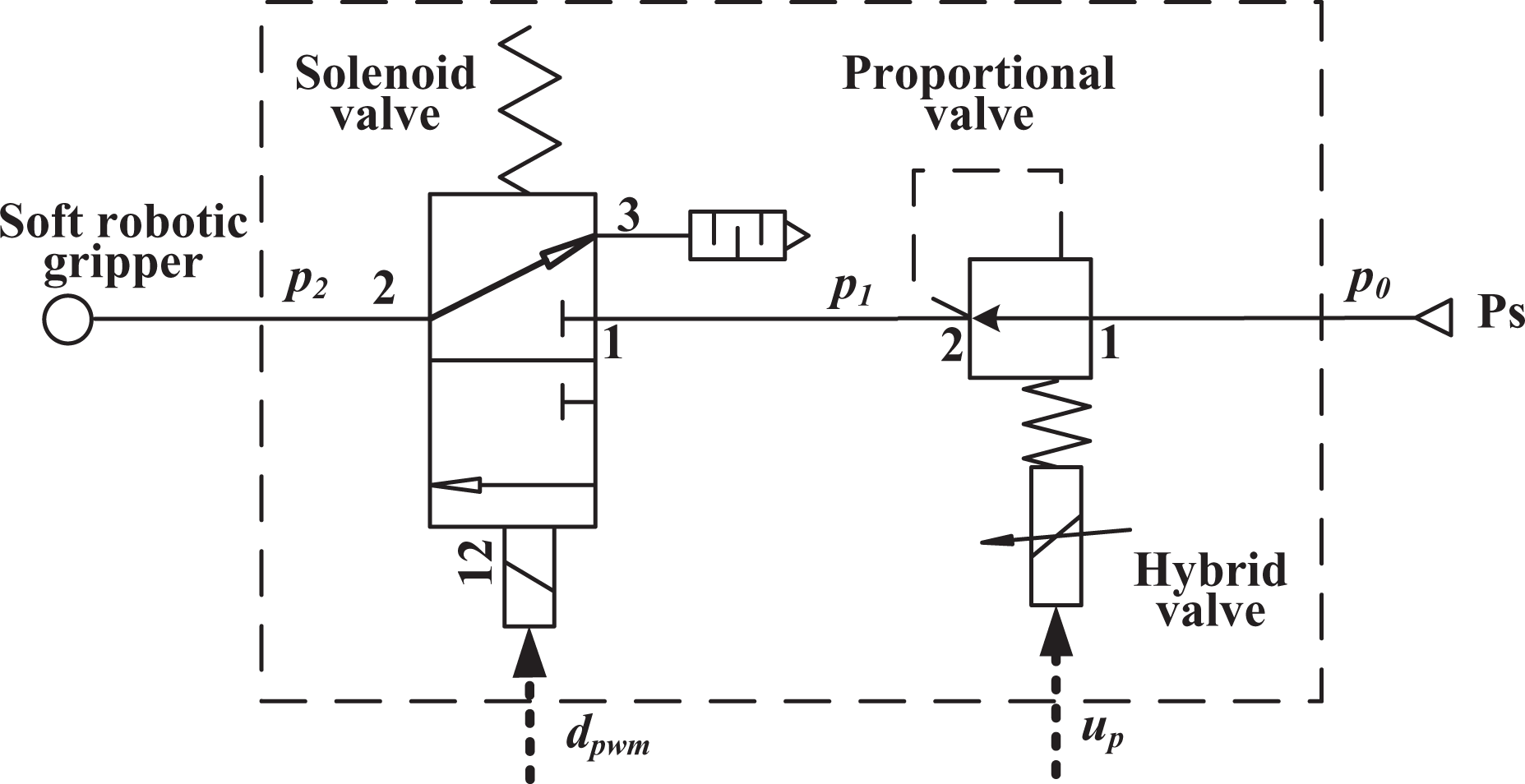
The principle of hybrid valve pneumatic control scheme.
The input of proportional valve is the PS, so that the input air pressure of proportional valve is

where
The output air pressure of proportional valve is controlled as
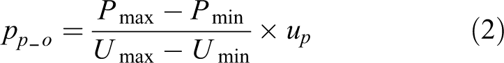
where Pmax and Pmin are the maximum and minimum adjustable pressures of proportional valve, respectively; Umax and Umin are the corresponding maximum and minimum control voltages, respectively.
Here, to ensure the proportional valve operating on ideal mode, it is necessary to set the air pressure of PS exceed to the maximum adjustable pressure of proportional valve, that is

With the solenoid valve, the input air pressure is same as the output of proportional valve, that is

where p
1 is the air pressure in the first place of the air channel of SRG system and
The output air pressure

where dpwm is the duty ratio of PWM signal and p 2 is the air pressure in the end place of the air channel of SRG system.
Substitute equations (2) and (4) into equation (5), the output air pressure pout of the air channel of SRG system is rewritten as

In equation (6), pout is calculated as the proportional valve and solenoid valve work on the regulation mode. In practice, the proportional valve has state of lock and regulation and the solenoid valve has the state of lock, on/off, and regulation.
The lock state of proportional valve (lock p ) is defined as
The lock state of solenoid valve (lock s ) is defined as

The working state of solenoid valve (state s ) is defined as
Considering all the state of proportional valve and solenoid valve, the output air pressure pout of the air channel of SRG system is expressed as
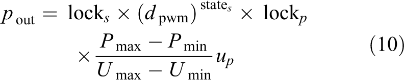
Further, pout is expressed with piecewise function as

The mode definition of HVPC is shown in Table 1. Only if one lock state of proportional valve and solenoid valve is lock, the HVPC is belonged to mode 1. If lock states of proportional valve and solenoid valve are working, and the working state of solenoid valve is on/off, the HVPC belonged to mode 2, otherwise, the working state of solenoid valve is regulation, the HVPC belonged to mode 3.
The mode definition of HVPC scheme.a

HVPC: hybrid valve pneumatic control.
a x is the arbitrary value.
The electric control of HVPC scheme
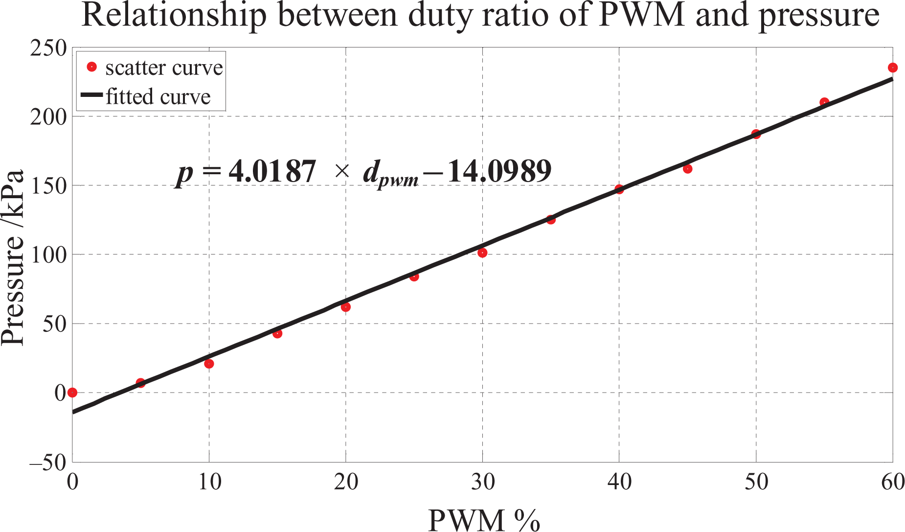
Figure 7 shows the electric control system of HVPC scheme. The control system includes upper and lower computers. The host computer as upper computer is used to perform human–computer interface. The embedded controller as lower computer is used to perform MC-HVPC method and output analog voltage and PWM signal with digital–analog converter (DAC) and timer module, respectively. MC-HVPC output control command for proportional valve with analog voltage and solenoid valve with PWM signal. The amplifier circuit is employed to amplify current of analog voltage signal. The transistor circuit is used to amplify current of PWM signal. The pressure sensor measures the internal air pressure of SRG.
The electric control system of HVPC scheme. HVPC: hybrid valve pneumatic control.
For proportional valve, the command of analog voltage is produced with DAC. The output analog voltage is controlled as

where n depends on the conversion bit of the converter, vref is the reference voltage of the converter, and vdac is the control value of DAC.
For solenoid valve, the command of PWM signal with the feature of fixed frequency and variable duty ratio is generated with timer module. The generation principle of the PWM signal is shown in Figure 8. A counter accumulates from zero to the period value V prd, then returns to zero for another period. When the count value equals to compared value V cmpr, PWM jumps to low level (0) from high level (1). The compared value V cmpr determines duty ratio of PWM signals.

The generation principle of PWM signal. PWM: pulse-width modulation.
The duty ratio dpwm is controlled as

where Vcmpr is the controllable compared value determining duty ratio of PWM signal and Vprd is the fixed period value determining the frequency of PWM signal.
MC-HVPC method
The modes classification of hybrid valve pressure control
There are three modes of hybrid valve pressure control, including pressure locking (PL) mode (mode 1), accurate pressure regulating (APR) mode (mode 2), and fast pressure regulating (FPR) mode (mode 3). These three pressure control modes are classed according to Table 1, and the mode classification is shown as in Figure 9. In the PL mode, any one of proportional valve and solenoid valve is lock (see Figure 9(a) to (c)), the air flow is stop, so that the air pressure in the place of the output port of the hybrid valve is zero. In the APR mode (see Figure 9(d)), the solenoid valve is on the state of normal open, or on/off state for a relative long period, the output air pressure of the hybrid valve jumps from zero (when solenoid open) to the output air pressure of proportional valve, so that the output air pressure of the hybrid valve is accurately controlled with the proportional valve by changing analog voltage. In the APR mode, the proportional valve plays the leading role, it is suitable for the application that requiring accurately adjusting pressure. In the FPR mode (see Figure 9(e)), the proportional valve limits a fixed air pressure, the solenoid valve adjusts output air pressure of hybrid valve from zero to the limitation air pressure by controlling the duty ratio of PWM signal. In the FPR mode, the solenoid valve plays the leading role, it is suitable for the application that requiring fast adjusting pressure.

The mode classification of hybrid valve pressure control: (a) proportional valve blocking, (b) solenoid valve blocking, (b) proportional and solenoid valves blocking, (d) proportional valve regulating, solenoid valve opening, and (e) solenoid valve regulating, proportional valve opening.
The MC-HVPC method
In order to perform three kinds of control mode of hybrid valve pressure control method, the control system includes upper and lower computers. In the upper computer, the main tasks are mode setting, mode recognition, and command sending. In the lower computer, the main tasks are command receiving, command parsing, and mode processing.
The control program in upper computer
Figure 10 shows the flow diagram of main program in upper computer. Firstly, set state of proportional valve. If the state of proportional valve is lock, recognize the mode as PL mode. If the state is not lock, set output pressure of proportional valve and set the state of solenoid valve. If the state of solenoid valve is lock, recognize the mode as PL mode. If it is not lock state, continue to judge the regulation state. If it is regulation state, set out the output pressure of solenoid valve and recognize the mode as FPR mode. If it is not regulation state, the mode is APR mode, but the switch way of solenoid is set as periodic way or manual way. After the mode recognition, send command to lower computer.

The flow diagram of main program in upper computer.
The control program in lower computer
Figure 11 shows the flow diagram of main program in lower computer. Firstly, receive command from upper computer, then perform command parsing, and go to the main interrupt which is periodically controlled by a timer. Next, judge the pressure control mode. If it is PL mode, lock the proportional valve and solenoid valve. If it is APR mode, regulate the proportional valve according to the setting output pressure of proportional valve. The control value of DAC is obtained by substituting equation (12) into equation (2), which is calculated as


The flow diagram of main program in lower computer.
Then, open the solenoid valve manually or set the periodic to open and close solenoid valve.
If it is FPR mode, limit the output pressure of proportional valve according to equation (14). Then, regulate pressure of solenoid valve. The control value of PWM signal is obtained by uniting equations (4), (5), and (13), which is calculated as

At last, go back to the main interrupt for another loop.
Experiment and results
Experiment platform
In order to test the performances of HVPC and verify the feasibility of MC-HVPC method, an experiment platform as shown in Figure 12 is set up.

Experiment platform.
The platform includes a PC, power supply, embedded controller board with CPU of STM32F407 (STMicroelectronics, Inc., Italy), an amplifier circuit and proportional valve (VEAB-L-26-D9-Q4-v1-1R1, Festo Inc.), a transistor circuit and a solenoid valve (MHE3-MS1H-3/2G-1/8-K, Festo Inc.), an air pressure sensor (SPAN-B11R-Q4F-PNLK-PNVBA, Festo Inc., Germany), and an air compressor (J3-4, JUN-AIR Inc., Denmark) supplying PS. In this system, the PC as upper computer performing command sending and data monitoring and embedded controller board as lower computer running the MC-HVPC control algorithm. Moreover, there are two kinds of SRGs, SC-SRG is good at grasping round-short objects, while TC-SRG is good at grasping narrow-long objects. All the sections are connected according to the electric control system of HVPC scheme as shown in Figure 7.
The performance test
Response performance
In order to analyze the performance of HVPC scheme, comparative experiments are performed by comparing HVPC scheme, individual proportional valve scheme, and individual solenoid valve scheme.
For every scheme, four types of step signals of pressure jump are tested, every step signal testing was repeated 10 times. These step signals included 0–60 kPa, 0–120 kPa, 0–180 kPa, and 0–240 kPa. The response times of rising edge, falling edge, and double edges were compared. The experiment results of response performance are shown in Figure 13. Viewing from Figure 13, the respond performance of the pneumatic control schemes of individual solenoid valve and hybrid valve exceed to individual proportional valve. These two schemes only spend a half time of scheme of proportional valve (see Figure 13(c)). In the rising edge, the scheme of hybrid valve is slightly better than the scheme of individual solenoid valve (see Figure 13(a)). While, in the falling edge, the scheme of individual solenoid valve is better than the scheme of hybrid valve (see Figure 13(b)). In the double edges, the schemes of hybrid valve and individual solenoid valve are almost equivalent, but hybrid valve win by a hair (see Figure 13(c)).

The compassion of respond performance: (a) Response time of rising edge respond, (b) response time of falling edge, and (c) response time of double edges.
Stability performance
The steady-state error of above four types of step tests for three kinds of pneumatic control schemes are analyzed. The statistical variances of steady-state error are shown in Figure 14. Each kinds of air pressure are sampled 10 times, and the steady-state errors in different conditions are calculated, so we can calculate the variance of the steady-state errors. Viewing from Figure 14, the individual proportional valve scheme has the worst steady-state performance, while the hybrid valve scheme has the best performance, the solenoid valve scheme is in the middle place.

The variance of steady-state error.
To summarize, the hybrid valve scheme has the advantages of fast response and accuracy steady-state performance. Therefore, the HVPC scheme is an optimal option for soft robot.
Feasibility of MC-HVPC method
APR with manual way
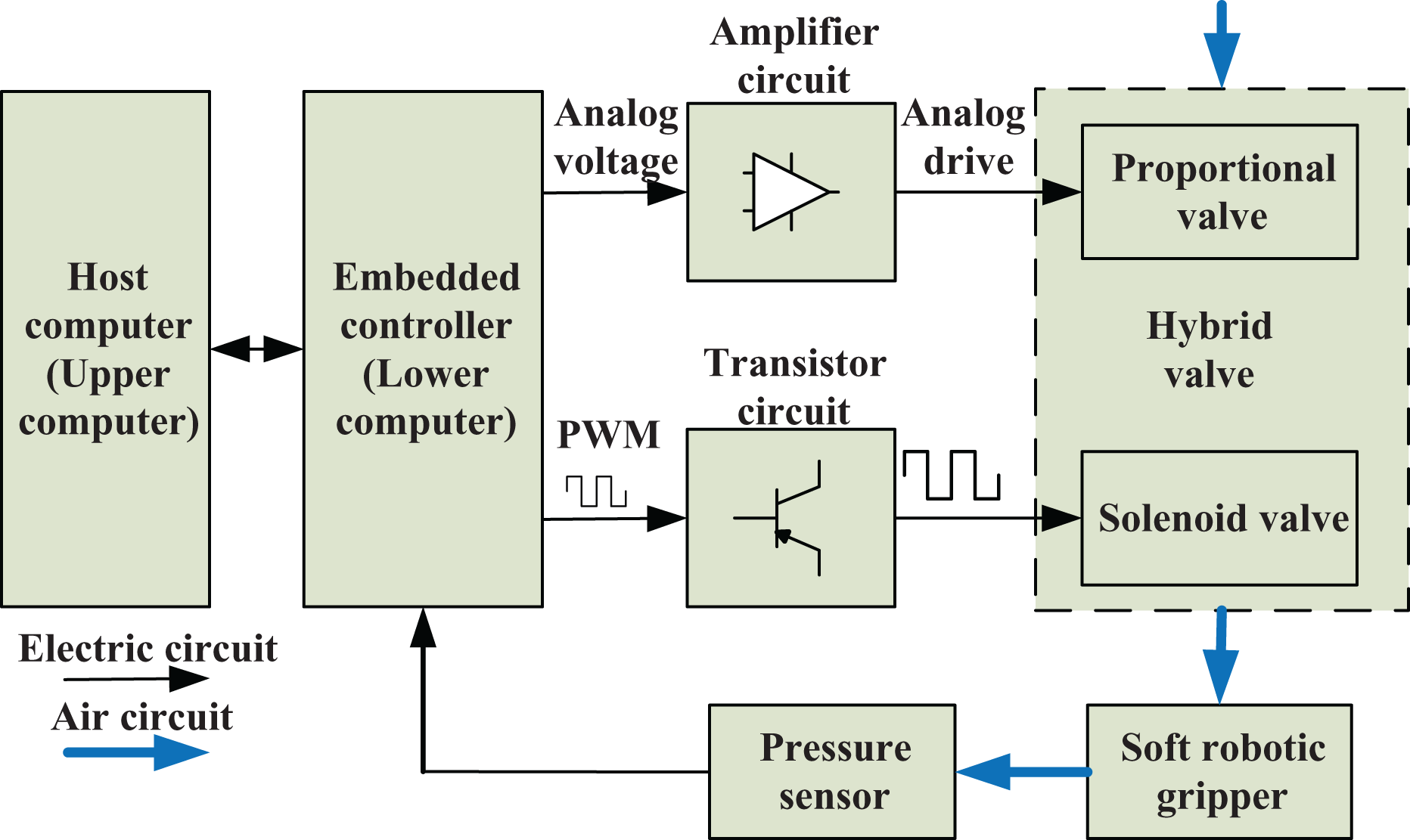
Figure 15 shows the grasping experiments for different objects. The grasped objects cover apple, orange, kiwi fruit, small orange, glue, banana, water bottle, and light tube. The first four objects are round and short, so that SC-SRG is employed to grasp them. The back four objects are narrow and long, so that TC-SRG is employed to grasp them. The related weight of objects and the corresponding controlled pressure are listed in Table 2. In this experiment, the MC-HVPC method adopts APR mode, and the corresponding pressure is accurately controlled. The switch way of solenoid valve is manual mode. When the grippers contact the objects, the switch of solenoid valve is opened to let the pressure air flow into the soft actuators to pick up the objects. When the grapping task finishes, the switch of solenoid valve is closed, so that no air flows into the soft actuators.
The grasping experiments for different objects: (a) grasping with SC-SRG and (b) grasping with TC-SRG. TC-SRG: twin contact-soft robotic gripper; SC-SRG: single contact-soft robotic gripper.
The weights and controlled pressure for different objects.

APR with periodic way
In order to adapt to automatic system, the pressure should be controlled automatically. Figure 16 shows the experiment results of APR with periodic way. The setting output pressure of the proportional valve is 180 kPa and the corresponding control value of DAC vdac is 1860, so that the analog voltage is 1.5 V, because of that the bits of DAC is 12 bits. The solenoid valve is on and off to open and close air channel with the switching period of 2 s. The experiment results reveal that the hybrid valve can perform APR mode in a periodical way and can achieve fast response with changing pressure.

The experiment result of APR mode with periodic way. APR: Accurate pressure regulating.
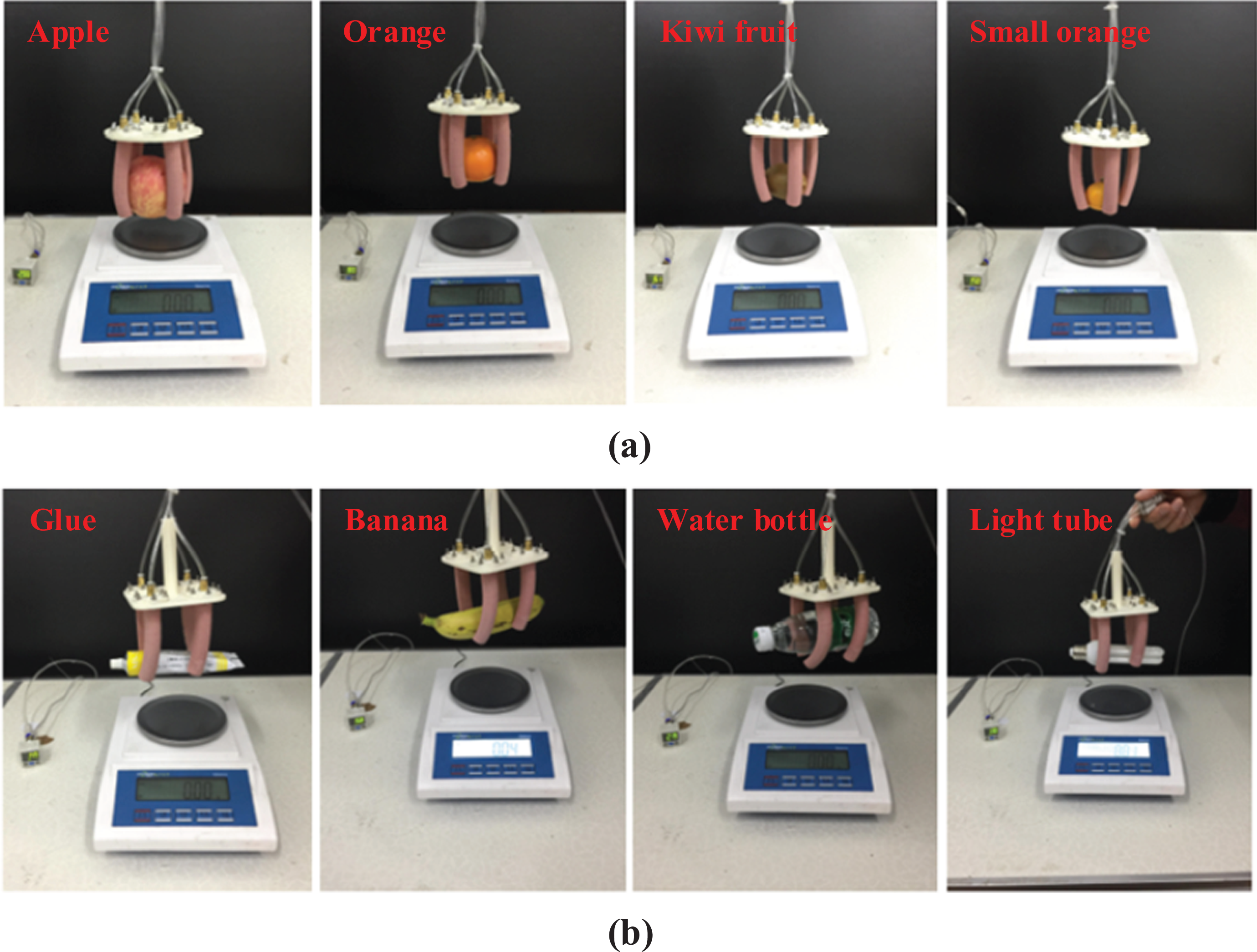
Fast pressure regulating
In the FPR mode, the proportional valve is adjusted with analog voltage, and the solenoid valve is adjusted with the duty ratio of PWM. For the aim of obtaining a repeatable curve between the duty ratio of PWM signal and air pressure to realize FPR mode, a calibration test of solenoid valve is required. Figure 17 gives calibration results of 3/2-way PWM-solenoid valve. The output air pressure of proportional valve is controlled at 500 kPa invariably. The fitting result shows that the relationship between duty ratio of PWM and air pressure is

Calibration results of 3/2-way PWM-solenoid valve. PWM: pulse-width modulation.
When duty ratio of PWM is 10%, the air pressure is controlled at 21.4 kPa. When duty ratio is 50%, the output air pressure of the hybrid valve system is 187.2 kPa. In this test, the duty ratio is limited under 60% for acquiring a linear relationship.
Conclusion
In this article, we have designed and manufactured two kinds of SRGs, which are SC-SRG with circular distribution of soft actuators and TC-SRG with rectangle distribution of soft actuators for grasping round-short and narrow-long objects, respectively. For the pneumatic control of SRGs, we proposed a novel HVPC scheme with combining proportional valve and solenoid valve. Further, we proposed an MC-HVPC method to perform pressure control in PL, APR, and FPR modes. The experiment results reveal that the proposed HVPC scheme outperforms the schemes of individual proportional valve and individual solenoid valve, in the aspects of performances of response and stability. Moreover, the feasibility of MC-HVPC is verified by the tests of APR mode with manual way, APR mode with periodic way, and FPR mode.
In the future, we will deeply research the HVPC method. For example, (1) employ one proportional valve and several solenoid valves to construct a multichannel pneumatic loop; (2) perform automatic mode switch adaptively by introducing different sensors (like fiber curve sensor) into the control system.
Footnotes
Authors’ contribution
Haiming Huang and Linyuan Wu have contributed equally.
Declaration of conflicting interests
The author(s) declared no potential conflicts of interest with respect to the research, authorship, and/or publication of this article.
Funding
The author(s) disclosed receipt of the following financial support for the research, authorship, and/or publication of this article: This work was financially supported by National Science Foundation of China under grant no. 61803267, China Postdoctoral Science Foundation funded project under grant no. 2017M622757, the Beijing Science and Technology program under grant no. Z171100000817007, the National Science Foundation of China under grant no. 61503212, no. 61771319, and Research Commissioned Project of Shenzhen University.