
Abstract
Industry 4.0 describes the future production of workpiece in job shop as: the workpiece is a smart one; it knows the details of how to manufacture itself; and it can communicate with manufacturing environment to support its own machining processes. This means that the production of workpiece places more emphasis on the smart realization of the process level in Industry 4.0. However, how to implement the production scenario based on existing technologies has not yet been well studied. On account of this, this article aims to study how to use existing technologies in job shop such as digital twins, Internet of Things (IoT), Cyber-physical Production System (CPPS), etc., to realize the workpiece-driven process-level production. The process-level production of a workpiece is divided into three stages according to the different manufacturing resources involved. On this basis, the production of the workpiece in digital twin job shop is divided into process level, operation level, and IoT/sensor level. Firstly, the manufacturing requirements at process level are generated according to production planning and process sheet. And these requirements are written into RFID tag of the workpiece. The workpiece dynamically interacts with different workstations via RFID reader/antenna in order to complete the manufacturing requirements. Secondly, based on the tag data, the interaction model of operation level, and IoT/sensor level CPPSs is given. Thirdly, at IoT/sensor level, the RFID devices are treated as a CPPS to track the manufacturing resources. And different smart sensors are used as independent sensor CPPSs to monitor the running status of machine tool. The RFID and sensor CPPSs are triggered by operation level CPPSs. Finally, a digital twin job shop is taken as an example to illustrate the feasibility of the proposed models and methods.
Keywords
Introduction
Industry 4.0, which is the most advanced one of future manufacturing systems, focuses on creating smart products, procedures, and processes. 1 According to the description of Industry 4.0, machines, products (i.e. workpieces) and manufacturing resources in job shop can naturally communicate with each other as in social networks. The workpieces know the details of how they were manufactured. They actively support the machining processes, answering questions such as “When was I made?,”“Which tools should be used to process me?,”“Where should I be delivered to?” etc. 2 Therefore, in the context of Industry 4.0, it is worth studying that how to use the process route of the workpieces and the production planning of the job shop to realize the production organization at process level and operation level.
The emergence of digital twin job shop provides effective support for realizing Industry 4.0 production scenarios.3,4 Obviously, the key to realizing the description of Industry 4.0 is when and what workpieces should communicate with the machining workstation to keep production going smoothly. It depends on three enabling technologies, that is, smart workpiece, Cyber-physical Production System (CPPS), and production data acquisition. The enabling technologies are briefly analyzed as follows.
(1) Smart workpiece. Smart workpiece, also called smart product or intelligent product, has attracted a lot of attention from practitioners and academics. Many researchers have given the definition of smart workpiece according to their application domain.1,5 McFarlane et al. 6 gathered definitions, characteristics, and terminologies that have been associated with intelligent product since the early 2000s. Although there are some slight differences between the existing definitions, 7 some common properties can be found, including unique identification code; storing data about itself; being capable of communicating effectively with its environment; reacting and adapting to environmental and operational changes. Those properties can be well solved by RFID. Therefore, when a workpiece is equipped with RFID tag, it can be viewed as a smart workpiece. 8 A large number of practical applications of smart workpieces are explored in supply chains, asset management, product lifecycle management, manufacturing, and so on. To get the real-time information of products in supply chain, and allow products to assess and influence their own destiny, Wong et al. 9 built specification of smart product. For ensuring an effective and efficient management of medical equipment to promptly and reliably deliver a diversity of clinical services at the patient bedside, Castro et al. 10 achieved an intelligent asset management by using RFID. The case study demonstrates that RFID enabled medical equipment has the potential to change asset management by improving inventory management, enhancing asset utilization, and increasing information visibility. Smart product makes it possible to collect information from any product lifecycle phases. In product lifecycle management (PLM), a conceptual approach of integrated reconfiguration management was introduced based on the smart product. 11 In an RFID-enabled manufacturing system, the state data of smart product was transferred to a computer and stored in product data management (PDM) for querying and processing. 12 In manufacturing domain, Wang et al. 13 used smart workpiece to enable decentralized control system of flexible automated production line. They presented a hybrid-data-on-tag approach to ensure the production procedures of workpiece runs smoothly in the case as network connection fails or there is no network. Leitão et al. 14 presented an implementation of a system of intelligent products where an agent-based solution was deployed in a factory plant producing laundry washing machines. Kovalenko et al. 15 presented and tested a product agent architecture with the capabilities to explore the local environment, plan, and schedule events based on its knowledge, and request desired actions from the resources in the system. Although some achievements have been made about smart workpiece, the use of smart workpiece is still in its infancy, especially in manufacturing domain.
(2) CPPS. Cyber-physical Production System is a core component of Industry 4.0.16,17 It monitors the physical production processes, and uses computations and communications so as to add new capabilities to the physical systems. 18 According to the definition, CPPS can be regarded as having been presented within the manufacturing domain for quite some time, for example, embedded controllers, sensor systems, robots. However, the ever-changing needs of society and market make the product become more complex, and also make the production difficult to adapt quickly. To meet the needs, the production system of job shop consists of an enormous variety of equipment, ranging from RFID and smart sensors to robots and conveyors, including metering devices, different controllers, different users, and so forth. Therefore, today, CPPS adopted in manufacturing is to increase the production system openness, autonomy, distributed control, adaptability, and integration. And it can raise the level of autonomy of production components. 19 CPPS is an interconnection of all components (machines and systems) along the value chain forming a flexible and smart automation system expected to be effective, safe, and efficient for reorganization at run time. 20 The implementation of CPPS would lead to significant changes in the working environment, especially in manufacturing and production control systems. 21 Agents are typically characterized as communicating, collaborative, intelligent entities applied for distributed problem solving. The inherent characteristics of agent technologies can provide sufficient means to realize CPPS. 22 There have been some examples to reflect the new characteristics of CPPS in manufacturing. Ding et al. 23 established a digital twin-based cyber-physical production system, and discussed its configuring mechanism, operating mechanism, and real-time data-driven operations control. Based on real-world examples, Mordinyi and Biffl 20 discussed the strengths and limitations of best-practice approaches in CPPS engineering. Since almost all improvements of existing production systems take place in real and active manufacturing sites, Gronau 24 presented a hybrid lab approach to simulate various degrees of autonomy. To decrease clamping errors in workpiece positioning, Denkena et al.25,26 achieved a sensory clamping system which provided hydraulic clamping elements with sensory capabilities to enable condition and process monitoring of the clamping system inside the harsh environment of a machine tool. Vogel-Heuser et al. 27 presented an architectural approach to implement Cyber-Physical Production System based on the technology of multi-agent systems and knowledge models. Rehberger et al. 28 designed a coordinating product management agent for CPPS, focusing on ensuring dependable behavior during runtime. The product management agent autonomously calculated solutions for a given product recipe. Indeed, plenty of CPPSs applied in manufacturing can be found from the literature. Most of them focus on remote monitoring and control. Some of them discuss the production realization from customer needs to the plant or the production planning. But the realization of smart production at process level, operation level, and even sensor level is rarely involved.
(3) Production data acquisition. The success of smart production systems highly depends on the reliable provisioning of the required information to the point-of-need, at the correct time, and without human intervention. 29 By capturing and processing production data, the smart workpiece can realize automatic monitoring and context awareness. 30 However, deficits would be observed in the course of automated acquisition of process data as well as the evaluation, quantification and analysis of the gathered data in job shop.31–33 In fact, the production data can be divided into two main categories: discrete and continuous. The discrete production data mainly includes the time-sensitive state and position changes of workpiece-related, operator-related, and tool-related (machine tool-related, cutting tool-related, fixture tool-related, and measuring tool-related) manufacturing resources. And it can be captured by manual entry, mobile terminator, or RFID.34–38 Although the collection of discrete production data by manual entry and mobile terminator is relatively simple, there are inevitably human errors in the data. More importantly, the efficiency of two data collection methods cannot meet the requirements of rapid production. As for RFID, it can automatically identify manufacturing resources, and periodically repeatedly read all covered RFID tag data through an RFID reader to capture time and location information. However, most of the captured data are repetitive and useless. They should be filtered by production control system (PCS).39,40 The continuous production data is dynamic, mainly including running data of machine tools, such as energy consumption, vibration, temperature, noise, etc., and it would be captured by special sensors. However, the amount of captured data is very huge, usually reaching multi-megabytes in 1 min. 41 Moreover, the data is machine tool-centered. Thus, it is very hard to be associated with a specific workpiece. In traditional job shop, operators can use keyboard, mouse, or touchscreen to trigger the sensor start/stop capturing. It is very easy to find the association between the data and specific workpiece based on operator actions. But in digital twin job shop, the sensors need to be triggered automatically in order to cooperate with the production procedures of the smart workpiece.
From the above analysis, it can be seen that the existing researches on the production of workpieces in job shop for Industry 4.0 are only conceptual or framework. However, Industry 4.0 emphasizes the realization of the process level production. How to implement the production scenarios based on existing technologies has not yet been well studied. Therefore, this article is devoted to realize the workpiece-driven process-level production by using the existing technologies in job shop such as digital twins, Internet of Things (IoT), CPPS. Firstly, the production realization model of a workpiece in digital twin job shop is presented. Secondly, based on current technologies of digital twin job shop, the communication approach between workpiece and different level CPPSs is presented. Thirdly, the trigger models for RFID CPPS and sensor CPPS are designed by using operation level CPPSs.
The remainder of this article is organized as follows: Section II describes the production realization model of a workpiece in digital twin job shop. The generation approach of manufacturing requirements at process level from the Gantt chart and the process sheet is depicted in section III. The interaction model between process level and the operation level CPPSs is discussed in section IV. In section V, the trigger models for RFID CPPS and smart sensor CPPSs are proposed. In section VI, a process-level production of a workpiece is taken as an example to illustrate the utility of the proposed models and methods. Finally, discussion and conclusion are presented in section VII and section VIII, respectively.
The hierarchical model of CPPS in a machining process for digital twin job shop
To better understand digital twin job shop and RFID, the definitions are given as follows:
According to the description of Industry 4.0, the realization of the process level production should include three stages at least: (1) the manufacturing requirements of the workpiece are sent to corresponding machining workstation. This can be implemented at process level using the RFID tag of the workpiece and smart conveying system; (2) the machine tool cooperates with other manufacturing resources to complete the machining tasks at operation level; (3) the production procedure is tracked and monitored by sensors.
Digital twin job shop is conducive to the realization of the following three aspects at least.
(1) Process level. Workpiece can not only obtain all the machining processes information including manufacturing resources, processing methods, operations, and quality requirements, but also store its current status such as current process. When the workpiece reaches a desired machining workstation, it can actively communicate with the workstation. Otherwise, the workpiece ignores the workstation, and keeps silent. In other words, the machining tasks and requirements of the production planning can be stored in the corresponding workpiece. Therefore, the production of job shop is pushed by all workpieces. According to the previous introduction to smart workpiece, the workpiece in digital twin job shop can be viewed as a smart workpiece. Therefore, the following workpieces in the digital twin job shop default to smart one.
(2) Operation level. In digital twin job shop, CPPS is the base of collaborating production, which comprises smart machines, storage systems, and manufacturing resources. It is capable of autonomously exchanging information, triggering actions and controlling each other independently. In a machining workstation, there are multiple CPPSs representing different manufacturing resources and different control level. Therefore, the workpiece, different level CPPSs and different manufacturing resources CPPSs should work cooperatively with each other.
(3) IoT/sensor level. In digital twin job shop, there are many smart sensors which provide large quantities of diverse real time production data (big data). However, if the smart sensors capture production data indiscriminately, the production data is not only huge, but also include large number of redundant data, noise, and even error data. To obtain useful data and reduce the production data size, the smart sensors should be notified when to capture data in time. Therefore, the smart sensors should be effectively coordinated according to the manufacturing procedures of the process.
Generally, the workpiece from raw material warehouse would be delivered sequentially to the machining workstations according to its process route by logistics operator. When the workpiece arrives at the desired workstation, it would be machined on the machine tool. During the machining procedures, other manufacturing resources, such as cutting tools, fixture tools, and measuring tools, would be used to help achieving machining tasks. At same time, sensors would start to capture the real time production data.
From the discussion above, it can be seen that the production of the workpiece in a machining process involves three levels, as Figure 1 shows. Therefore, the CPPSs can be extracted from three levels.
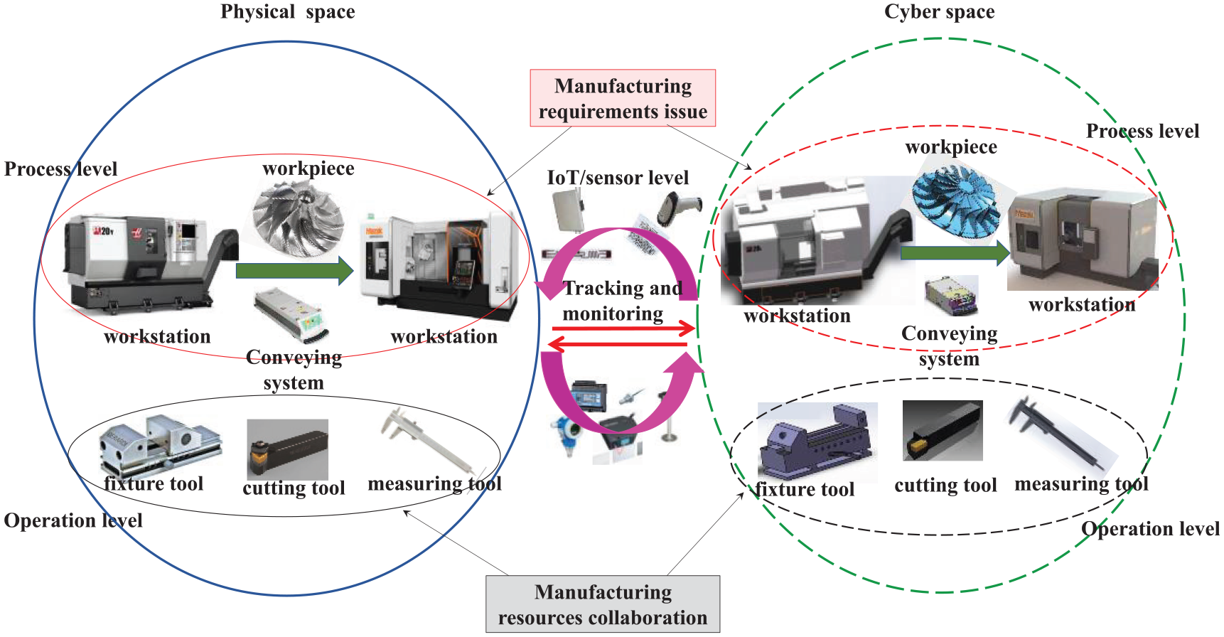
The hierarchical model of CPPSs in a machining process.
At process level, there are three CPPSs. For example, the smart workpiece can be viewed as a CPPS, which can be written as SW. SW can communicate with other CPPSs by using RFID technology. Conveying system including logistics operator and delivering vehicle can be considered as a CPPS (CV). CV can use a vehicle-mounted RFID reader to know the transport route of the workpiece. In digital twin job shop, every machining workstation includes operator, machine tool, and sensors, it can be integrated as a CPPS (MW). MW can read the manufacturing requirements from the RFID tag, and complete the machining tasks of the process independently. It’s important to note that the human being is viewed as a part of CPPS in this article, which only assists the CPPS to achieve the corresponding work. This is because under Industry 4.0, the human being is expected to be freed from manual execution, and manufacturing resources can respond to local needs quickly with no human intervention.
At operation level, different types of manufacturing resources should cooperative with each other to ensure the production runs smoothly. Thus, the operation level CPPSs can be extracted according to the manufacturing resource type. The manufacturing resources mainly include cutting tool-related, fixture tool-related, machine tool-related, and measuring tool-related at operation level except operator. The corresponding CPPSs are cutting tool CPPS (CT), fixture tool CPPS (FT), machine tool CPPS (MA), and measuring tool CPPS (MT), respectively. Note that CT, FT, and MT can be considered as public CPPSs for all processes, which provide the corresponding tool services to all workstations.
At IoT/sensor level, each smart sensor has been equipped with embedded computer and network. Therefore, one smart sensor can be viewed as a separate CPPS. The sensor CPPSs are private for the process because most sensors are installed in the machine tool. Additionally, according to the definition of CPPS, RFID devices in a workstation can also be treated as a CPPS.
Although the number of sensor CPPSs is different at different workstations, the type is same. The sensor CPPSs in a workstation, according to the sensor data, can be surely divided into two categories: discrete CPPS and continuous CPPS. Note that IoT/smart sensor level is viewed as an interface for mutual mapping between physical space and cyber space, as Figure 1 shows. And IoT/smart sensor can also be viewed as part of CPPS of manufacturing resources. However, this article treats all smart sensors separately as a CPPS because there are some public sensors, such as RFID, in the job shop.
The manufacturing requirements of a workpiece
Generally, when an order is sent to the job shop, PCS would make a production planning in the form of Gantt chart, which determines explicitly the workstation, the start time, and end time of each machining process, as Figure 2(a) shows. The ith machining process

where

The production planning of a workpiece: (a) the Gantt chart of production planning and (b) the machining process of a workpiece.
From the production planning, the total machining processes of any workpiece k can be deduced, as Figure 2(b) shows. It can be formalized as follow:

where PL is the production planning of the digital twin job shop.
Because the Gantt chart is at process level, it cannot provide more detailed processing means, processing steps, operations, quality requirements, and other information. But the information should be told to the workstation by the workpiece in smart process. The process information can be found in the process sheet of the workpiece, for example, Table 1 shows the process sheet of an impeller. The formalization of the process sheet can be described in following mathematical model:

where
The process sheet of an impeller.

Hence, the process level manufacturing requirements of the workpiece k for the workstation can be obtained from the equations (1) and (3), as described as follows:

And the manufacturing requirements of workpiece k for all processes can be expanded from the equations (2) and (4), as described as follows:

The manufacturing requirements are combined with current status of the smart workpiece CSk, to form the tag data Ptk. The data can be stored on the network/RFID tag in the form of text format such as Extensible Markup Language (XML) or other abbreviation means.
The interaction of process level and operation level CPPS
The communication between process level CPPS
At process level, the communication between SW, CV, and MW should keep pace with the material flow of the workpiece in digital twin job shop, as the red arrows and blue arrows indicate in Figure 3. When the workpiece leaves raw material warehouse, PCS sends the tag data to SW (i.e. writing the tag data onto RFID tag, as the first red arrow shows). Next, the workpiece is put into the delivering vehicle, and CV is informed of the current process of the workpiece (see the second red arrow and blue arrow). CV transports the workpiece to the assigned workstation of current process (see the third blue arrow). When the workpiece reaches the workstation, MW gets current process manufacturing requirements through RFID reader, which includes the operation level manufacturing requirement (see the third red arrow). When the manufacturing requirements are achieved, MW sends the manufacturing results to SW, as the fourth red arrow shows. Finally, SW updates its own current status in the tag data, and the workpiece is continually transported to next workstation (see the fourth blue arrow).

The communication between process level CPPSs.
The interaction model of MW and the operation level CPPS
For modeling the interaction between MW and the operation level CPPSs, the material flows of different manufacturing resources in a workstation should be firstly depicted. The material flow of a workpiece in the workstation can be further divided into several lower-level stages, as the red arrows in the Figure 4 shows. (1) When the workpiece arrives at the entrance of the workstation, the porter hoists it from the delivering vehicle by using a crane to enter the in-buffer of the workstation waiting for machining. (2) If the workpiece is ready to be machined, the porter will hoist it from the in-buffer onto the machine tool. (3) The workpiece is in machining process until all requiring machining tasks of current process are completed. (4) The workpiece is put into out-buffer and waits for machining quality inspection. (5) The porter hoists the workpiece from the out-buffer onto the measuring table, and the measurer captures the machining results with measuring tools according to the quality requirements of the process. (6) The porter hoists the workpiece from the measuring table onto the delivering vehicle and transports it into next workstation.
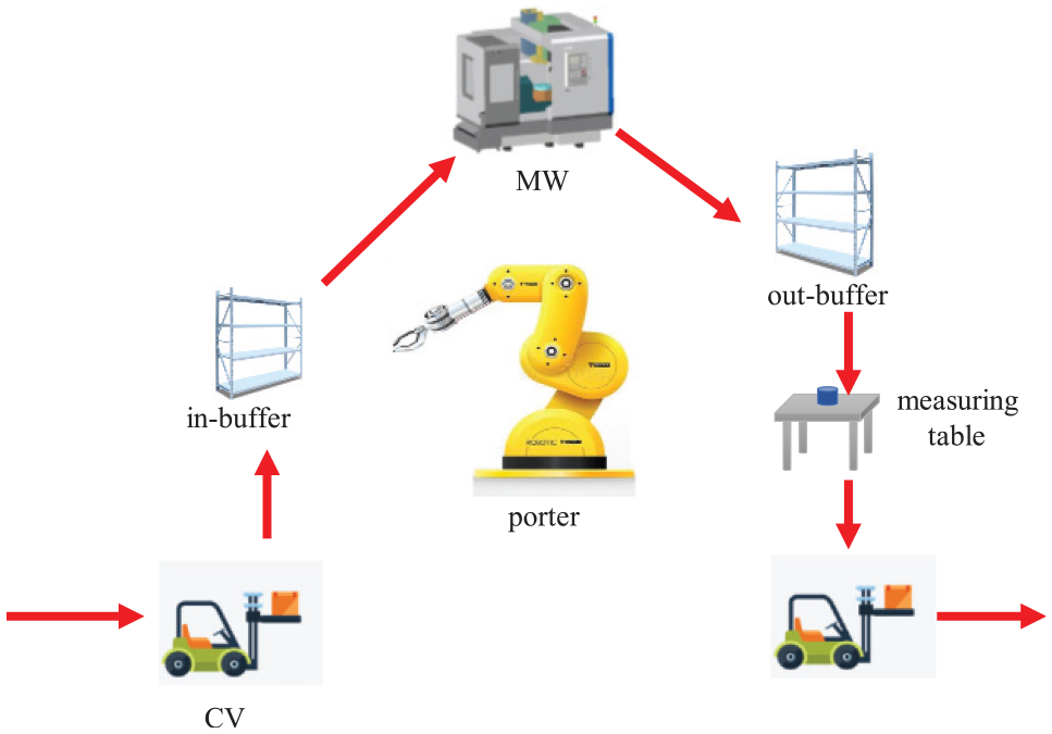
The material flow of a workpiece in a workstation.
In the machining stage, fixture tools, cutting tools, and measuring tools should be used to help the operator complete the machining tasks. For example, in a processing step, the workpiece should be fastened onto the machine tool by fixtures, and the cutting tools should be mounted onto the machine tool before actual machining. During the machining stage, the operator uses the measuring tools to confirm the machining results. After the processing step is completed, those tools are returned to the warehouse. And new tools would be sent to the workstation in next processing step. The procedure is repeated until all processing steps are achieved.
According to above material flows, the interaction model of MW and the operation level CPPSs can be established, as Figure 5(a) shows.
(1) MW parses the tag data from SW. Firstly, MW finds the manufacturing requirements for the workstation
(2) When the workpiece is in the in-buffer, MW sends the tool applications to MT, FT, and CT respectively for the first processing step. At the same time, MW sends the first processing step operation to MA. When MT, FT, and CT receive the tool applications, they would transport the corresponding tools to the workstation promptly.
(3) If the workpiece is loaded on the machine tool and everything is ready, MA starts to achieve the first processing step. After that, MA feeds the machining results back to MW. Meanwhile, when the applied tools are returned to the warehouse, tool CPPSs send the tool usage information to MW.
(4) If the first processing step operation is finished, MW sends new applications to all tool CPPSs and MA for next processing step, and so on.
(5) When all required processing steps are finished, MW inspects the machining results, and sends the machining quality data to SW.
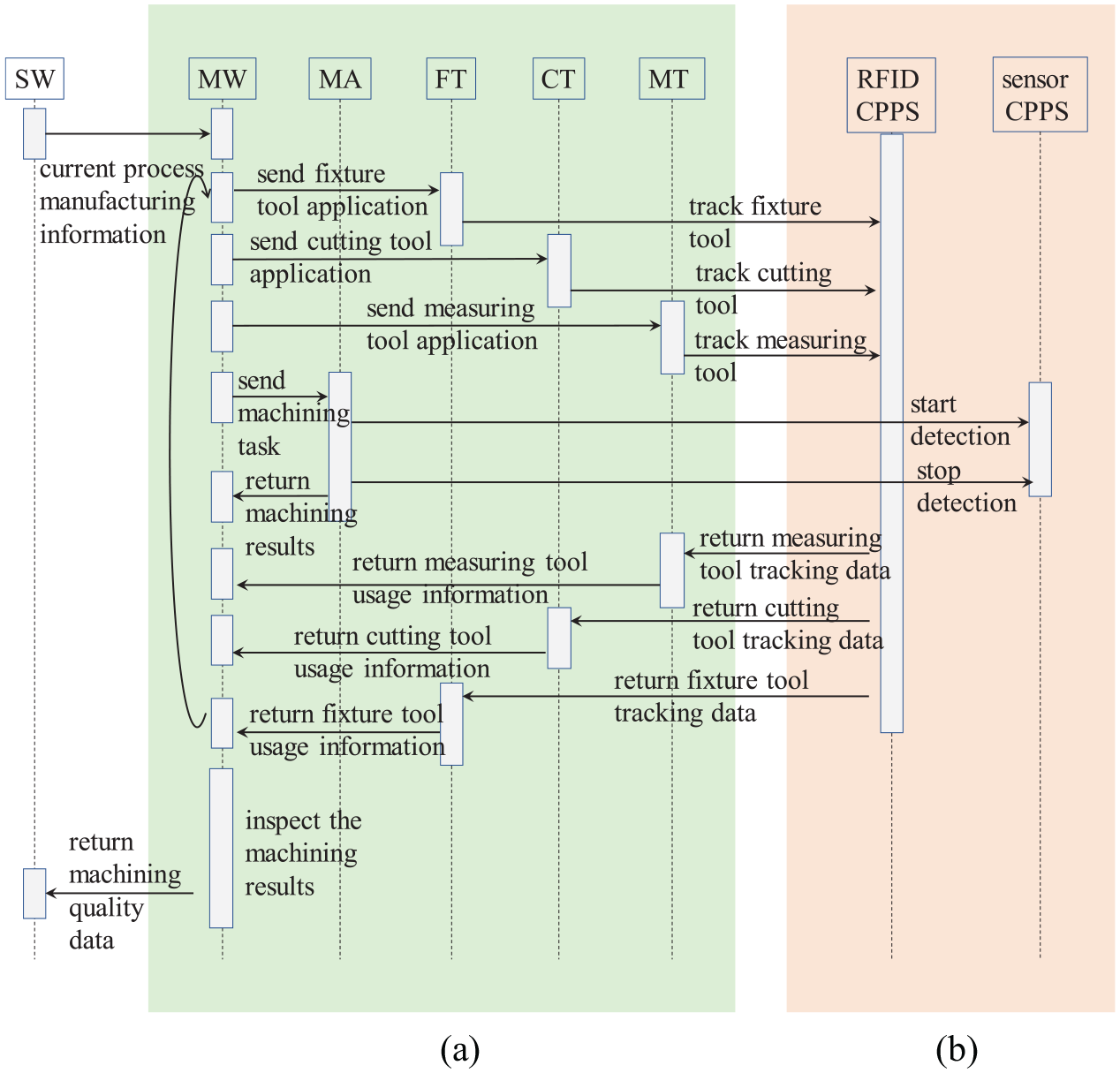
The interaction of operation level and IoT/sensor level CPPSs: (a) the interaction of MW and the operation level CPPSs and (b) the trigger models for RFID CPPS and smart sensor CPPS.
The trigger models of sensor CPPS
As discussed earlier, the discrete production data can be captured by RFID reader/antenna, and the continuous production data can be captured by smart sensors. But they should be triggered at appropriate time in the production procedures of the workpiece. Here, two different trigger models are designed for RFID CPPS and smart sensor CPPS.
The trigger model for RFID CPPS
In digital twin job shop, RFID devices can be viewed as a discrete CPPS (i.e. RFID CPPS), which can track the workpiece and operation level tool-related manufacturing resources in the workstation through RFID antennas.
RFID CPPS can be triggered by operation level tool CPPSs, as the left part of Figure 5(b) shows. For example, when FT receives the fixture tool application from MW, it can convert the application into a trigger command immediately. The trigger command is to notify RFID CPPS which fixture tool should be tracked from now on. When the fixture tool is returned to the warehouse, RFID CPPS ends the fixture tool tracking, and sends the tracking data to FT. FT uses the tracking data to form the fixture tool usage information. The communication between other tool CPPSs and RFID CPPS is the same as FT.
Note that MA can also trigger the RFID CPPS. For example, MA can send a request to RFID CPPS, which asks for RFID CPPS to track the workpiece.
The trigger model for smart sensor CPS
Because the continuous production data captured by smart sensor is very huge, it is very hard to real time store the data on the backend database. Usually, the data is stored in the memory of smart sensor. Therefore, smart sensor CPPS only needs to be told when to start/stop the detection.
Smart sensors are mainly used to monitor the running status of machine tool, and MA is responsible for the machining process of the smart workpiece. Thus, MA can easily associate the continuous production data with the smart workpiece, as Figure 5(b) shows. When MA acquires the machining tasks from MW, it sends a start detection command to all equipped smart sensor CPPSs. And then, the smart sensors capture the continuous production data. When MA accomplishes the machining tasks, it sends a stop detection command to all smart sensor CPPSs. Next, the smart sensors stop their respective capture progresses.
Case study
The introduction of experiment environment
To verify the proposed approach, a digital twin job shop in our lab is taken as an example. It has three workstations (see Figure 6(a) Machine tool #1, Machine tool #2, Machine tool #3). All workstations are connected together by AGV. There are two industrial robots (Industrial robot #1 and Industrial robot #2) and two in-out buffers (In-out buffer #1 and In-out buffer #2). The Industrial robot #1 and In-out buffer #1 are used for Machine tool #1 and Machine tool #2, but the Industrial robot #2 and In-out buffer #2 are used only for Machine tool #3. Additionally, the measuring table is shared by three workstations. Note that the in-out buffer is the combination of the in buffer and the out buffer.
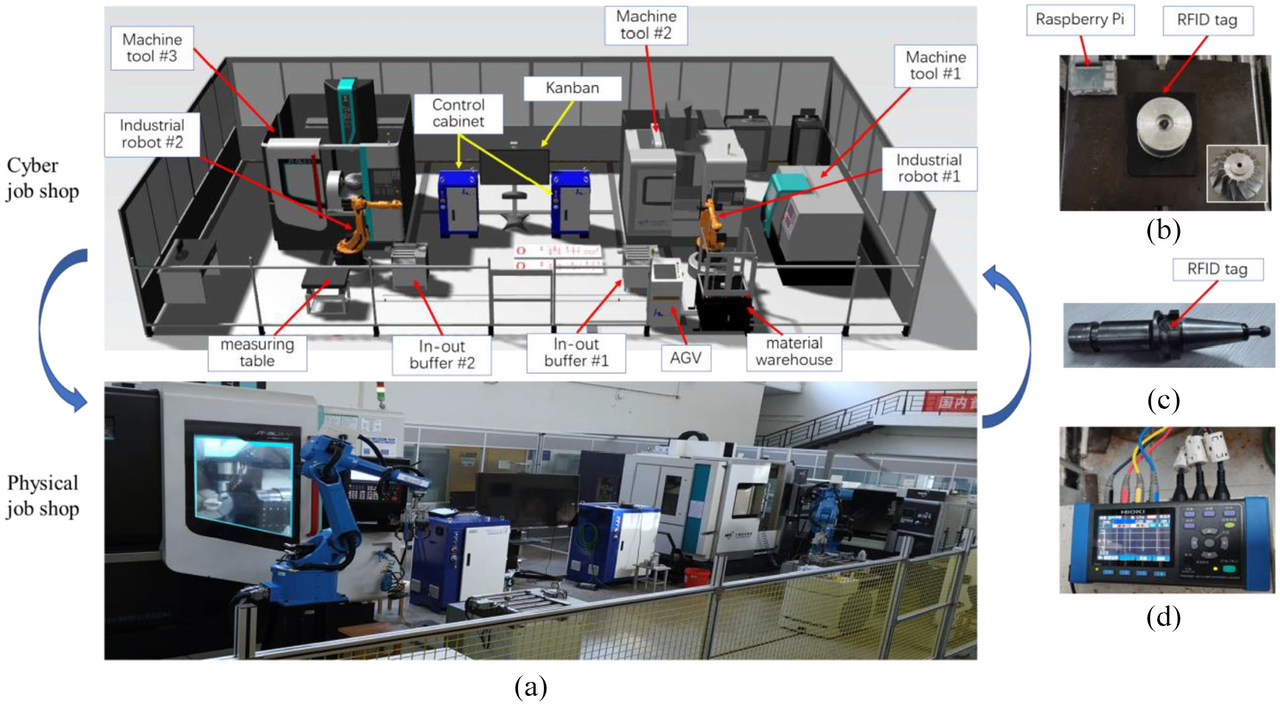
A digital twin job shop in the experiment: (a) the layout of the production digital twin job shop and (b) The workpiece (impeller), (c) the cutting tool, and (d) The energy sensor.
In this job shop, the measuring tool, fixture tool, machine tool, and cutting tool are configured with sensors, RFID tag, embedded system device, and numerical control system to collect the real-time manufacturing data, as Figure 6(c) and (d) show. And the workpiece is equipped with RFID tag, as Figure 6 (b) shows.
For explanatory purposes, one workpiece, called as impeller-1, is chosen as an example. Its process sheet is given in Table 1. Workstation 3 is used as an example to illustrate the production procedures of impeller-1. According to the CPPS hierarchical model in Figure 1, the three CPPSs of process level (SW, CV, and MW) are instantiated as impeller-1, AGV, and workstation 3, respectively. The CPPSs of operation level (CT, FT, MT, and MA) are instantiated as cutting tool, fixture tool, measuring tool, and Machine tool #3, respectively. At IoT/sensor level, the RFID CPPS is instantiated as RFID reader and RFID antenna. And the sensor CPPS is instantiated as energy sensor. Some instances are equipped with communication modules, such as RFID tag and Raspberry Pi, which are used to implement their communication and computing. The details of the instances are listed in Table 2.
The instances of CPPS in workstation 3.

In this case study, JSON 45 is used to develop the adaptive protocol adapters for different CPPSs. The adaptive protocol adapters can make the PCS to be integrated with existing industrial controllers. The interfaces of the adaptive protocol adapters involved in this case is listed in Table 3. Note that: in Table 3, the module is a kind of software to analyze the protocol, and acquire the data generated from the device; the interfaces are parts of the protocol adapters, which are used to connect to the device, send the request and receive the response, and decompose the raw response data to semantic data. Based on that, OPC UA is used to standardize the adaptive protocol adapters.
The instances of the adaptive protocol adapters.

Specifically, the socket modules are used to communicate with two industrial robots. And the data acquired is to monitor the changes of the robot pose or speed. For AGV, the socket interface is used to build a connection. Then, the data from/to AGV is encoded/decoded. The HTTP interface is used to build a connection with Machine tool. The JSON coder is took to encode/decode the data from/to HTTP. MQTT and SDTI is used to build connection with RFID reader and energy sensor, respectively.
The tag data of impeller-1
Figure 7 shows the production plan that the PCS schedules for an order. From the Gantt chart, it can be found that the production planning of impeller-1 consists of three processes.

The production planning of impeller-1.
The production information of three processes are
According to the process sheet (see Table 1), the machining information of three processes are
Based on above information, the tag data of impeller-1 can be generated in XML, as Figure 8. In this case, the basic manufacturing requirements (e.g. identification code (ID), current status, all machining processes, quality requirements) are stored on the RFID tag. And more detailed manufacturing requirements are stored on backend database.

The tag data of impeller-1.
The communication between different CPPS
Figure 9 depicts the manufacturing information obtained by the process level CPPS, the operation level CPPS, and the sensor CPPS during the workpiece machining in workstation 3. The communication between different CPPSs for “impeller-1” production in workstation 3 is as follows.
The tracking information of tools in the last processing step.
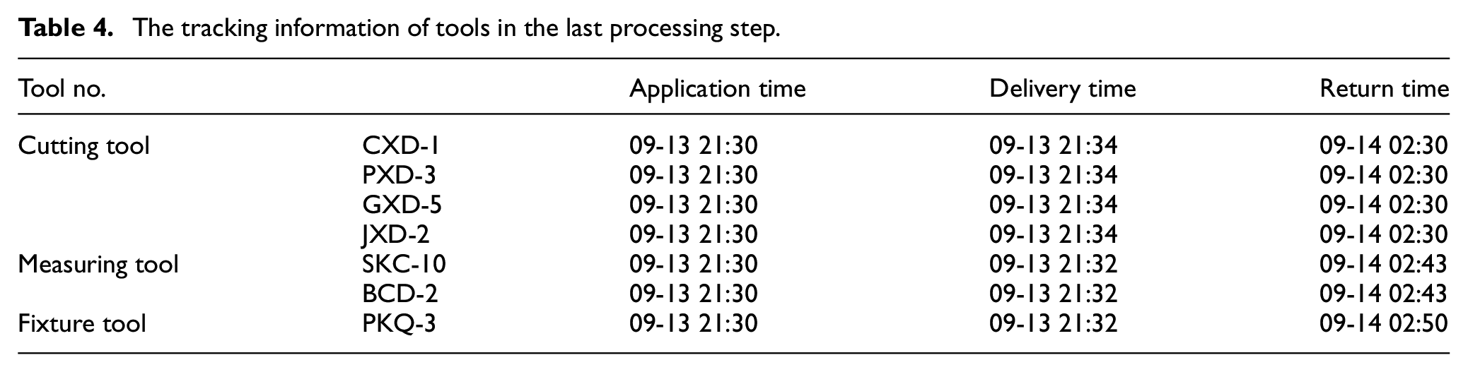
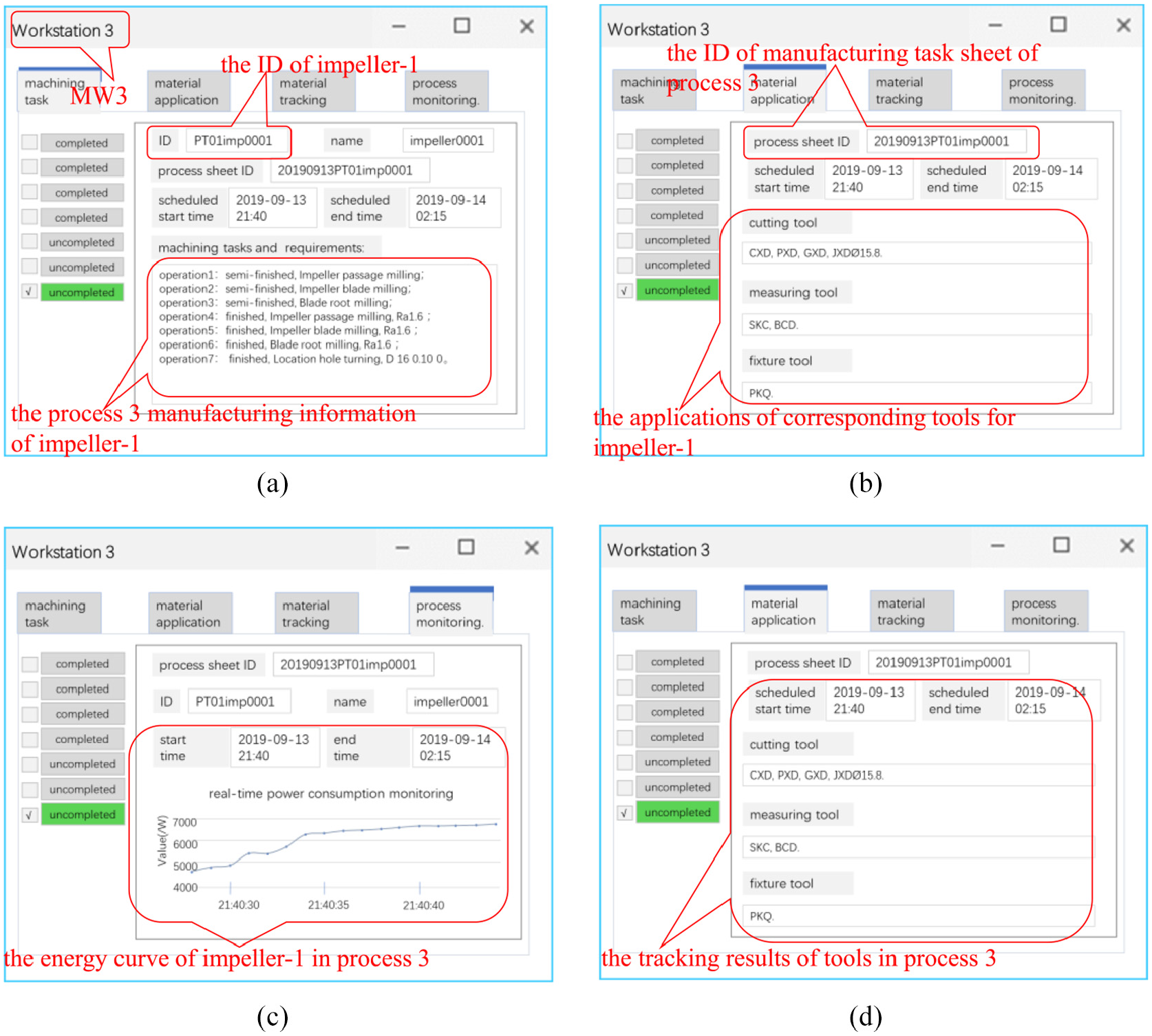
The communication results between different CPPSs in workstation 3 for impeller-1: (a) MW3 gets the manufacturing requirements of impeller-1, (b) MT, FT, and CT, respectively receive tool application from MW3, (c) energy sensor CPPS gets the trigger application and (d) MW3 receives the tracking information from MT, FT, CT, and MA3.
Discussion
Compared with present workpiece production in smart/digital-twin job shop, there are two advantages:
(1) Compared with the existing research on smart/digital-twin job shop, this article mainly focuses on how to realize the smart production of workpiece at the process level based on current technology of job shop. The interaction of manufacturing resources in a process is analyzed, so as to ensure the smooth completion of workpiece production in accordance with the assumption of industry 4.0.
(2) Compared with current PCS and CPPS, this article can effectively associate the material flow, control flow and information flow around the process level production of a workpiece. It is beneficial for subsequent production process tracing and production data mining. For example, the analysis granularity of production data can be refined to each machining operation, and the results would be more precise and accurate.
However, there are still following issues need to be discussed.
(1) While human being is a part of CPPS, he does not dominate the manufacturing procedure. What human being need to do is only assist the CPPS to achieve the corresponding manufacturing requirements. At different automation levels, human being would perform different tasks; even human being is exempted from CPPS. For example, in the case study, the machine tool operator is replaced by industrial robot.
(2) The computation and data of workpiece can be separated from its body. The computation can be realized at local or remote (cloud). Obviously, local computation needs the assistance of embedded system. Moreover, the data can be stored as data-on-network or data-on-tag. The data-on-network approach allows a low memory RFID tag to link the data on the backend database. The data-on-tag approach requires the RFID tag to have enough memory for storing all data about workpiece.
(3) The focus of this article is on the process-level production. Therefore, it only shows the production realization in a workstation in detail. Actually, based on the proposed models and methods, the work can be easily expanded into the whole production procedure of the workpiece.
Conclusions
This article proposes a method to realize smart CPPS enabled process-level production of workpieces in digital twin job shop. According to the description of Industry 4.0 about workpiece production scenarios, this article abstracts all manufacturing resources in a process, from process level and operation level to IoT/sensor level, into different CPPSs. It establishes the interaction between different CPPSs by using the material flows of corresponding manufacturing resources in a workstation. The proposed models and methods can not only realize the production of workpiece in a workstation but also collect real time discrete production data as well as continuous one effectively.
The contributions of this article are three-folded. Firstly, this article uses the RFID tag of smart workpiece to store its manufacturing requirements of all processes. The tag data generation method based on the production planning and the process sheet is shown in great detail. Secondly, it presents a hierarchical model of CPPSs in a machining process. At process level, workpiece, conveying system, and machining workstation are abstracted into SW, CV, and MW. At operation level, CT, FT, MT, and MA represent the different tool warehouses and machine tool respectively. At IoT/sensor level, the RFID devices in a workstation is viewed as a RFID CPPS to capture the separate production data, and every smart sensor is treated as an independent sensor CPPS to capture the continuous production data. Thirdly, it defines the interaction between different CPPSs. At process level, SW communicates with CV and MW in order to tell them current manufacturing requirements of the workstation. At operation level, MA communicates with CT, FT, and MT in order to coordinate different manufacturing tools. At IoT/sensor level, RFID CPPS, and sensor CPPS communicate with operation level CPPSs for capturing production data effectively. Compared with present workpiece production, smart CPPS enabled process-level production of workpieces can be easily adjusted and expanded. And smart workpiece can enable more customized production and more system flexibility.
All the technologies used in this article for the process-level production of the workpiece have been widely applied in digital twin job shop. And the proposed models and methods can effectively associate the interaction of the manufacturing requirements, autonomous collaboration of manufacturing resources, and tracking and monitoring of the manufacturing procedure. Therefore, the work can be easily reproduced in the other digital twin job shop, for example, automotive and furniture digital twin job shop. Note that, the manufacturing resources, such as cutting tool, fixture tool, measuring tool, or AGV, would be absent in some job shop. Therefore, the corresponding CPPS, such as CT, FT, MT, and CV, would be realized by other CPPS.
There is also some work listed as follows to be addressed in future. Firstly, the production planning would be inevitably rescheduled in practice. Therefore, the process level production realization of workpiece should consider the production switching from the old production planning to the rescheduled one smoothly. Secondly, the job shop usually has multiple machine tools of same type. And the workpiece can be machined by different machine tools for one process. Thus, the realization of the best process level is that the workpiece can choose dynamically appropriate machine tool for current process.
Footnotes
Handling Editor: James Baldwin
Declaration of conflicting interests
The author(s) declared no potential conflicts of interest with respect to the research, authorship, and/or publication of this article.
Funding
The author(s) disclosed receipt of the following financial support for the research, authorship, and/or publication of this article: This work was supported in part by the China Postdoctoral Science Foundation under Grant 2018M643727, Soft Science Research Project of Shanxi Province under Grant 2019KRM122, Special scientific research plan of Education Department of Shaanxi Provincial Government under Grant 20JK0922, National Natural Science Foundation of China under Grant 51975463.