
Abstract
Rotary-wing unmanned aerial vehicles (UAVs) are widespread in both the military and civilian applications. However, there are still some problems for the UAV design such as the long design period, high manufacturing cost, and difficulty in maintenance. Therefore, this paper proposes a novel design method to obtain a lightweight and maintainable UAV frame from configurable design to detailed design. First, configurable design is implemented to determine the initial design domain of the UAV frame. Second, topology optimization method based on inertia relief theory is used to transform the initial geometric model into the UAV frame structure. Third, process design is considered to improve the manufacturability and maintainability of the UAV frame. Finally, dynamic drop test is used to validate the crashworthiness of the UAV frame. Therefore, a lightweight UAV frame structure composed of thin-walled parts can be obtained and the design period can be greatly reduced via the proposed method.
Introduction
In the last decades, unmanned aerial vehicles (UAVs) are widely used in both military and civilian applications. In the military applications, the UAVs are widely used for border patrol and target tracking missions. And in the civilian applications, the UAVs are used to provide medical supplies and surveillance of topography. 1 Recently, at numerous civilian processes, the UAVs are utilized to perform new missions with attached payloads such as cameras, thermal infrared sensors, and similar apparatus. 2
Many researchers have made some improvements in disturbance rejection, stable flight, endurance, and carrying capacity of the payload. Chen et al. 3 proposed the tilted-rotor configuration design method to select the best design parameters and components according to the particular payload and hovering time, so as to accurately maintain the position in a turbulent wind environment and improve the disturbance rejection capability. Similarly, Zhang et al. 4 analyzed the influencing factors of the wind disturbance rejection capability according to static equilibrium analysis of the quadrotor, and obtained the corresponding improvement methods. Then, Lee et al. 5 designed a new type of multi-rotor UAV with stable and constant flight performances, which can carry many types of cargo. Recently, Kumar et al. 6 proposed a reconfigurable design method by using the newly active-passive motor scheme to improve the throttle response of the multi-rotor UAV and increase the carrying capacity of the payload. Moreover, De Martini et al. 7 proposed an over-actuated quadrotor platform with double axes tilting propellers to fly across narrow passages that the traditional quadrotor UAVs cannot pass. Additionally, the UAV frame, as the main components of the UAV, can protect the control systems and power system. The research of the UAV frame is also very important.
Currently, many UAV frame design methods have been performed to enhance the strength and reduce the weight. Leomar et al. 8 analyzed the UAV frame strength in different take-off and landing conditions, which minimized the potential damages during different missions. Then, computer-aided design software was applied to design the UAV frame for short-term use at the 2 kg payload by Singhanart. 9 In particular, it is very important to reduce the weight of the UAV frame while maintaining the structural performance, which can reduce the energy consumption and improve the carrying capacity of the payload. Lee et al.10,11 used high modulus composite material to optimize the UAV frame, whose structural weight was further reduced. Additionally, lightweight metal alloys and injection-molded foam were also used to reduce the weight and improve the UAV strength and stiffness. 12 Afterwards, Ferro et al.13,14 combined the topology optimization method with 3D printing technology to manufacture the complex and lightweight UAV frame. Topology optimization has been implemented as a powerful structural design method in engineering applications at the early stage of the design process, because it can generate lightweight and innovative layouts for product design. The researchers used topology optimization methods to optimize a variety of components.15,16 However, the UAV frame design methods still have problems such as long design period, high manufacturing cost, and difficulty in maintenance. Few researchers used the thin-walled parts derived from the topology optimization method to construct the UAV frame. The peculiarity of this kind of frame is that it can reduce time and cost through the stamping process.17–19
Therefore, a comprehensive structural design method is innovatively proposed to obtain a lightweight and maintainable UAV frame in this paper. The configurable design is implemented to determine the initial geometric domain of the UAV frame. Topology optimization method based on inertia relief theory is used to transform the initial geometric model into the UAV frame structure. Process design is considered to improve the manufacturability of the UAV frame. Furthermore, the thin-walled components are used to construct the UAV frame because of the high stiffness-to-mass ratio and maintainability. Finally, dynamic drop test is used to simulate the impact condition and validate the crashworthiness of the UAV frame.
Configurable design
Figure 1 shows the flow chart from configurable design to detailed design. The configurable design is presented to determine the geometric dimensions of some components. The topics of the configurable design are summarized as follows: the dimensional features of propellers, motors used in the mechanical system, and the determination of the minimum wheelbase.

Flow chart from configurable design to detailed design.
In the configurable design of the frame, an initial data that complies best with the requirements should be determined: the maximum take-off weight, the maximum thrust-to-weight ratio, and the payload. Then, the geometric dimensions can effectively be determined through the maximum thrust force required for each propeller, which can be calculated as:

where F is the maximum thrust force of a rotor, Mmax represents the maximum take-off mass, P is the maximum thrust-to-weight ratio, and the number n of propellers is related to the different load requirements and design motivation. Furthermore, as the number of blades increase, the maximum thrust force may increase, but the effectiveness of the propeller may reduce. Hence, the multi-rotor UAVs generally use two-blade propellers. 20
It is crucial to choose appropriate brushless motors and propellers because they are closely relevant to the thrust force produced and delivered to the UAV. The drag force of the UAV is mainly produced because of the usage of propellers and it is closely linked to the brushless motor’s speed constant (KV). 20 The specifications of motors and propellers can be used to design the UAV, as listed in Table 1. Generally, large-sized propellers should be matched with motors with a small KV value to improve the thrust force of the multi-rotor UAVs.
Specifications of motors and propellers.

The geometric relationship between the wheelbase L and the maximum propeller radius rmax is shown in Figure 2, and the corresponding mathematical expression is:

with


Types of propellers: (a) quadrotor, (b) hexarotor, and (c) eight-rotor.
To make the UAV frame as compact as possible, it is inevitable to satisfy the requirement, that is

where rp denotes the propeller radius, which is determined by the mass and payload of the UAV frame. Then, the minimum wheelbase can be directly acquired from (2).
The multi-rotor UAVs can be generally divided into quadrotor, hexarotor, and eight-rotor UAVs according to the number of rotors. The carrying capacity of the eight-rotor UAVs is higher than that of the quadrotor UAVs. Additionally, the layout of the frame is generally divided into two types: “+” and “X” for multi-rotor UAVs, as shown in Figure 3. The “X” type frame is widely used in agriculture for its best controllability. Therefore, according to the configurable design, the size parameters of the UAV frame are obtained to determine the initial design domain.

Layout of rotary-wing UAVs: (a) quadrotor layout, (b) hexarotor layout, and (c) eight-rotor aircraft layout.
Detailed design
Topology optimization design
After the configurable design of the UAV frame, the topology optimization method based on inertia relief theory is considered to obtain the optimized material distribution of the frame.21–23 Compared with the traditional design method, the design period can greatly be reduced by the topology optimization method. The objective of the optimization problem is to minimize the structural compliance under available volume constraint. It can usually be used to replace the dynamic analysis with static analysis so that the high-resolution topology optimization can be performed.
24
It is worth noting that the static analysis of the unconstrained UAVs need to account for the inertia relief.25,26 The so-called inertia relief theory is to subtract the calculated rigid body inertia from the given load vector

where

In equation (6),
The rigid body motion can still occur in the structure although the inertia relief method solves the force balance problem. Then, the structural stiffness cannot be solved because of the singularity of the matrix. Therefore, supporting point constraints (similar to single point constraints) must be set to eliminate the matrix singularity. There is no constraint force on the supporting point, so the effects of constraints on the local deformation and the force transmission path of the structure is negligible. The topology optimization problem based on inertia relief theory can be formulated as:
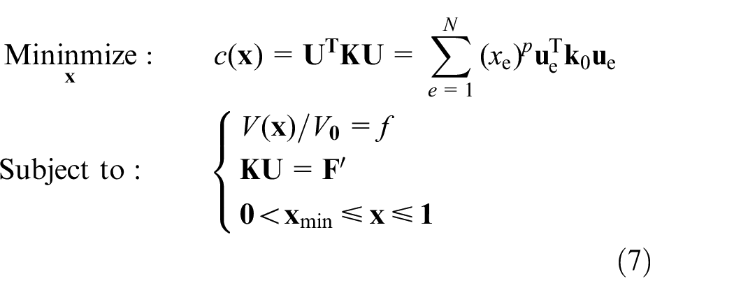
where
In this section, the UAV frame with eight-rotor for plant protection is introduced to illustrate the topology optimization procedure. Aluminum has greater potential for lightweight design, so we select aluminum alloy as the material of the UAV frame. Furthermore, the parameters of the initial structure and the other components are determined by referring to the DJI MG-1 plant protection UAV. The UAV uses DJI’s state-of-the-art A3 flight control, a solution specifically tailored to the agricultural environment. The model of flight battery and nozzles are MG-12000 and XR11001, respectively. The basic parameters of the plant protection UAV are listed in Table 2. It can be observed that the minimum wheelbase is 1468 mm acquired from (2) to (4). Additionally, the mass (Mz) carried by the UAV central hub can be defined as:

Basic parameters of the plant protection UAV.

Figure 4 describes the initial design domain of the UAV frame. The mass for the initial design domain is 5846 kg, which is meshed with 98,745 hexahedral or pentahedral elements. The average size of the elements is 15 mm. It is worth noting that the design domain does not contain the motor, propeller, medicine box, and nozzles.

Initial design domain.
Every propeller provides a vertical upward pull of 49.98 N. The payload of the UAV frame is 18 kg, which consists of batteries, radar, and other components. After the first topology optimization, there are still material redundancy problems although the remarkable topology optimization results have been acquired. Therefore, it is inevitable to perform further optimization to obtain new optimization result. Then, these optimization results are manually redrawn by using CAD software to reproduce the shape suggested by the topology optimization.
It is difficult to transform the topological structure into a manufacturable product using conventional manufacturing technologies while maintaining optimized performance. 27 For the topology optimization results, it is highly desirable that the solid cross-sections of the truss-like structures should be replaced by thin-walled cross-sections which have high inertia-to-mass ratio. 28 Figure 5 shows the topology optimization results of the UAV frame. It is very useful for further process design of the UAV frame although the optimization result is impossible to manufacture because the thickness of each point is different. Consequently, after the topology optimization, the optimization result needs to be adjusted in dimensions to obtain the optimal thickness of the structure so that the UAV frame can be manufactured.

Topology optimization results: (a) first optimization result and (b) second optimization result.
Process design
Stamping process
As a class of lightweight and crashworthy structures, the thin-walled structures are widely applied in engineering because of the high stiffness-to-mass ratio and maturing manufacturing process.29–32 For the manufacture of the UAV frame, the frame need to be sectioned to reduce the manufacturing cost and complexity at the early stage of the design process. The optimized UAV frame, which can be divided into eight arms and one central hub, is mainly composed of thin-walled parts, as shown in Figure 6. Stamping process is extensively used in the manufacture of thin-walled parts for its advantages of high manufacturing efficiency and material utilization rate.33–35 Therefore, the stamping process can effectively be used to fabricate the UAV frame in view of reducing the manufacturing cost.

Exploded view of frame: (a) UAV frame, (b) arm, and (c) central hub.
The eight arms are uniformly distributed. The diameters of the UAV frame and central hub are 1468 and 628 mm, respectively. The diameter of the motor mounting platform is 36 mm. Each arm consists of a mounting platform for motor, an upper panel, a lower panel, and ribs connecting the upper and lower panels, as shown in Figure 7. Moreover, the ribs and central hubs are also designed as simple thin-walled parts, as shown in Figure 8. In a word, all parts are designed as thin-walled parts to improve the maintainability of the UAV frame.

Exploded view of arm: (a) upper panel, (b) ribs, (c) lower panel, and (d) motor mounting platform.

Exploded view of ribs and central hub: (a) rib 1, (b) rib 2, (c) central hub 1, and (d) central hub 2.
Additionally, the size and shape of the geometric model need to be adjusted to obtain a lightweight thin-walled frame structure while maintaining the stiffness of the topological results and enhancing manufacturability. The upper and lower panels of two adjacent arms are designed as a whole to avoid too many connectors. At the same time, the small holes of each part are also deleted and the minimum size of each hole is not less than 10 mm, as shown in Figure 9. The thickness of the ribs and panels is 3 and 2 mm, respectively. The thickness of the upper and lower panels, motor mounting platform and central hubs is 2 mm, the thickness of ribs connecting the upper and lower panels is 3 mm, and the mass of the frame is 2.332 kg. The final UAV frame and the detailed design of each part are shown in Figure 9.

Exploded view of the UAV frame: (a) upper panel, (b) lower panel, (c) central hub 2, (d) central hub 1, (e) motor mounting platform, (f) rib 1, and (g) rib 2.
Joint process
Currently, the common types of joint process include welding, riveting, and bolt connection. Compared with welding and riveting, the large-volume UAV frame can be easily disassembled by bolt connection for maintenance and transportation, and it is more free to choose the materials of the connectors. 36 Therefore, the UAV frame uses bolts to connect various components. The bolts have three grades: A, B, and C (rough bolts). Figure 10 and Table 3 show the hexagon socket bolt specifications. The bolt yield limit is shown in Table 4. Considering the practicability and strength, the B grade M3 hexagon socket bolts can meet the requirements of the UAV frame.

Hexagon socket bolt.
Hexagon socket bolt specifications.

Bolt yield limit.

Figure 11 introduces the eight kinds of connectors between the different parts. The connectors are designed to be symmetrical so that the stress distribution is more uniform. Moreover, the distance between the bolt and the edge of connectors should be reasonably arranged from the manufacturing perspective. Referring to the national structural design specifications, 37 the diameter of the M3 hexagon socket bolts holes d0 is 3.2 mm, and the distance between the bolt and the edge of connectors is not less than 1.5d0.

Geometrical design of connectors: (a) connector of rib 1 and upper panel, (b) connector of rib 2 and upper panel, (c) connector of rib 2 and lower panel, (d) connector of rib 2 and upper panel, (e) connector of central hub 1 and central hub 2, (f) connector of rib 1 and rib 2, (g) connector of two lower panel, and (h) connector of two upper panel.
Crashworthiness validation
Drop test of the UAV is conducted by using finite element analysis to obtain the crashworthiness responses. Under the normal operation state of the fully loaded plant protection UAV, the maximum horizontal operating speed of the UAV is 4 m/s and the maximum height of flight is 3 m. The commercial finite element software LS-DYNA is used to simulate the frame dropping from the highest flight height for simulation validation. The landing gear is composed of aluminum alloy round rods with a cross-sectional diameter of 20 mm. To facilitate the study, the soil is simplified to an elastoplastic block.
During the simulation, the frame falling process is omitted, and the frame is directly given the speed at the moment of collision and contact, that is, the speed in the horizontal X direction is 4000 mm/s and the speed in the vertical Z negative direction is 7668 mm/s. Eventually, the geometric model is composed of about 100,000 elements including shell elements and solid elements, as shown in Figure 12. Figure 13 depicts all energy curves in the finite element calculation. It is worth noting that a large amount of kinetic energy is converted into internal energy at the end of the collision. Then, the hourglass energy should be within 5% of total energy to ensure the reliability of simulation results according to the ECE R66 standard.38,39 According to the simulation results, the transformation of kinetic energy into internal energy of the system is stable, and the hourglass energy is less than 5%.
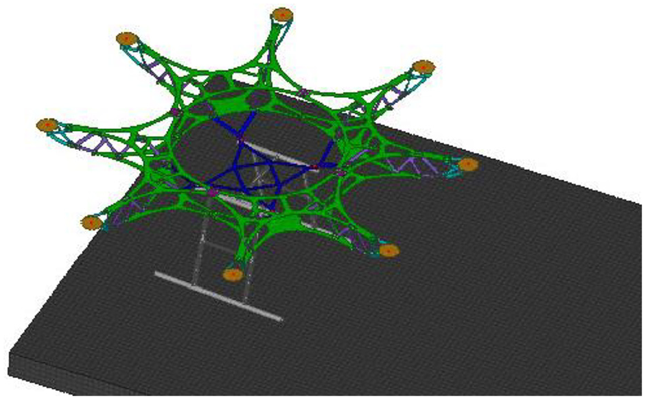
Crashworthiness validation.
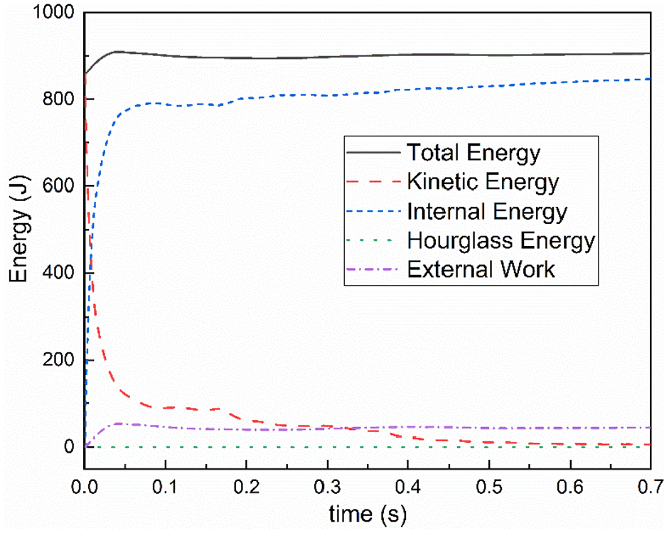
Energy curves.
The simulation results are shown in Figure 14. It can be observed that the UAV frame deformation is small. The maximum stress occurs at the central hub 1 of the frame structure, and plastic deformation occurs when the yield limit is reached. Although the central hub 1 fails during the dynamic drop test, it is convenient to be replaced and repaired for the part later, which meets the initial design requirements.

Von Mises stress for UAV frame: (a) 0.025 s and (b) 0.7 s.
Conclusion
A comprehensive design method is innovatively proposed to obtain a lightweight and maintainable UAV frame from configurable design to detailed design. First, the size parameters of the UAV frame are obtained to determine the initial design domain by configuration design. Second, the topology optimization method based on inertia relief theory is considered to obtain the optimized material distribution of the frame and reduce the design period. Third, a lightweight UAV frame structure composed of thin-walled structures can be obtained by the process design method, which improves the manufacturability and maintainability of the UAV frame. Finally, the dynamic drop test validates the crashworthiness of the UAV frame.
Footnotes
Handling Editor: James Baldwin
Declaration of conflicting interests
The author(s) declared no potential conflicts of interest with respect to the research, authorship, and/or publication of this article.
Funding
The author(s) disclosed receipt of the following financial support for the research, authorship, and/or publication of this article: This work was supported by Exploration Foundation of State Key Laboratory of Automotive Simulation and Control.