
Abstract
To realize eco-models based on (where 3R represents reducing, reusing, and recycling), both researchers and automobile development departments use controllable components to reduce vehicle fuel consumption and emissions. In this context, this paper presents the design of a double-ball motor control valve (DB-MCV). When compared with use of a traditional thermostat, use of the proposed valve in a Worldwide Harmonized Light Vehicles Test Cycle (WLTC) allows the coolant temperature to be controlled accurately as per the vehicle operating conditions, with control accuracy of ±1°C. Using this approach, the engine pre-heating time is reduced by 61 s, the total hydrocarbon (THC)) emission is reduced by 6.79%, the CO emission is reduced by 7.18%, and NOX emission is reduced by 4.84%. Under the same vehicle and working conditions, the engine fuel consumption is reduced by 2.31% on average. Under the cabin heating condition, the cabin temperature can be increased by 4.3°C, which improves the thermal comfort of the driver. When the vehicle is stopped after running at high speed and the engine is idling, the coolant temperature in the engine decreases rapidly, which reduces the risk of a hot dip occurring in the engine.
Keywords
Introduction
The automotive engine industry can neither be expanded for economic benefits only, nor limited for ecological benefits alone. On the contrary, economic development and ecological benefits should be coordinated together in an innovative manner. Previous studies have demonstrated that improving the engine’s thermal efficiency has both economic and ecological benefits. Enhanced thermal efficiency can not only improve engine fuel economy but also can reduce the emission of CO, NOx and other pollutants.1,2 Several studies have proposed different methods to improve engine thermal efficiency, including the use of innovative thermal management techniques.3,4
Engine thermal management is the integrated control of the engine combustion, cooling, lubrication and exhaust heat transfer processes. 5 The cold start and warm-up processes represent the main stages of engine work. When compared with normal operating conditions, the temperatures of the engine body, the coolant and the engine oil are low, friction losses and combustion losses are high, and the catalytic conversion efficiency of the exhaust gas is low (and may even not reach the light-off temperature), which results in increased fuel consumption and emissions.6,7 Therefore, it is necessary to improve the cold start performance and increase the warm-up speed. First, these changes will promote mixing of the intake and the fuel, optimize the combustion process, and reduce fuel consumption and emissions. 8 Second, the changes can increase the oil preheating rate and reduce friction losses. Wakuri et al. conducted oil temperature preheating and friction loss tests at an engine speed of 2000 r/min. Their results showed that when the oil temperature increased from 50°C to 80°C, the friction loss was reduced by 32%. 9 Third, such changes will shorten the light-off time of the three-way catalytic converter, improve the catalytic conversion efficiency, and reduce the emission of CO, hydrocarbon (HC) and NOx pollutants. 10 There are a number of ways to improve cold start performance and accelerate engine warm-up, including preheating the engine oil using the exhaust gas. Research by Burke et al. showed that this approach allowed the fuel consumption of the New European Driving Cycle (NEDC) to be reduced by 4%. 11 Through use of active cooling systems such as planetary gear (PG)-type water pumps, on-off electromagnetic clutch-type water pumps and variable position electromagnetic thermostats, the coolant flow can be controlled flexibly to enable a rapid increase in the engine operating temperature, thus reducing both fuel consumption and exhaust emissions.12,13
The engine combustion chamber is mainly composed of a cylinder block and a cylinder head. To improve the intake efficiency and reduce the exhaust temperature, a lower cylinder head temperature is required. However, to reduce the engine heat loss and increase the oil temperature, a higher cylinder block temperature is required. By using a separate cooling approach, the coolant flows in the cylinder block and the cylinder head can be controlled independently to keep these components within their optimal temperature ranges, thus reducing both heat loss and friction loss. This is an innovative improvement that combines both economic and ecological benefits.14,15,16,17
Modern cars require more efficient and smarter engine cooling systems, e.g. nucleate boiling cooling and intelligent thermal management systems.18,19,20 Nucleate boiling cooling is achieved by coolant vaporization near the combustion chamber wall and bubble disturbances will increase the heat transfer coefficient. Therefore, in this process, large numbers of bubbles should be avoided to reduce the heat transfer coefficient. Increasing the pressure will also increase the boiling temperature, which can further increase the engine operating temperature. Xu 21 and Mehdipour et al. 22 found that when the other conditions remain the same, an increase in pressure from 0.1 MPa to 0.15 MPa can cause the boiling temperature to increase by 10°C.
In an intelligent thermal management system, a control valve is used to control the flows of coolant to the warm air and the radiator. Using the NEDC cycle, control valves were tested under different operating conditions and the results showed that the fuel efficiency was increased by 1.23%, the cooling loss was reduced by 1.35% and the friction loss was reduced by 2.21% by these control valves. 23 Chalgren used electric water pumps and electric flow control valves in place of mechanical water pumps and thermostats, respectively. The engine’s working temperature and temperature control stability were improved as a result and the flow rate to the warm air was corrected to increase the cab temperature by 3°C to 5°C. 24 Haghighat et al. performed a simulation to verify an intelligent cooling system that consisted of an electric water pump, an electronic thermostat and a variable speed fan. Under NEDC test conditions, the coolant operating temperature was increased to 104°C, the fuel consumption was reduced by 1.1%, CO emission was reduced by 5.3% and the total hydrocarbon (THC) emission was reduced by 6.1%. 25 Therefore, use of a rational and intelligent thermal management system was beneficial in reducing cooling loss, friction loss and fuel consumption.
Their engine cooling system was mainly composed of a cooling water jacket, a water pump, a thermostat, a radiator and a fan. At present, most engines still use mechanical wax thermostats and there is a “lag” problem in the heating and cooling cycles that makes the engine’s operating temperature difficult to control accurately. 26 Therefore, using the M16N engine (Harbin Dong’an Automobile Power, Harbin, China) as a basis for our research, we developed the double-ball motor control valve (DB-MCV) and applied it to the engine’s intelligent cooling system (hereinafter referred to as the DB-ICS). The basic parameters of this engine are shown in Table 1.
Basic parameters of the M16N engine

The main part of the M16N engine cooling system is shown in Figure 1. The coolant outlet of the cylinder block and the cylinder head is connected with the DB-MCV water inlet, and the DB-MCV outlet is connected with the cabin heater, the oil cooler, the exhaust gas recirculation (EGR) cooler and the water tank. The above components and the water pump constitute the DB-ICS. This article mainly discusses the impact of the DB-MCV and the DB-ICS on engines and vehicles.

Cooling system connection diagram
Design and development of DB-MCV
The traditional thermostat adjusts the valve lift through the thermal expansion and low-temperature solidification processes of the wax, which causes the valve lift changes in the heating and cooling process to be relatively large and thus means that this type of thermostat cannot achieve precise control. 27 The DB-MCV designed in this section uses a motor to control the rotation of the ball valve to adjust the flow in the cylinder block and the cylinder head cooling water jacket with rapid response and precise control characteristics.
Design of DB-MCV
The structure of the DB-MCV is shown in Figure 2. The DB-MCV is mainly composed of a DC motor, ball valve 1, ball valve 2, a ball valve seat and a water temperature sensor. The valve also integrates the connection interfaces, including those of the cylinder block, the cylinder head, the EGR cooler and the oil cooler.

Structural drawing of the motor control valve
Control principle of DB-MCV
Conventional thermostats only control the flow path from the engine to the radiator.28,29 Use of dual thermostats can enable independent control of the circulation in the cylinder block and the cylinder head. 30 The DB-MCV controls the cylinder block, the cylinder head, the oil cooler, the EGR cooler and the large circulation path separately. The control principle of the engine’s intelligent cooling system (DB-ICS), which is composed of the DB-MCV, is illustrated in Figure 3 and is divided into seven cooling cycle modes.

(a) Rapid engine preheating, (b) cockpit heating and defrosting, (c) cylinder block flows (d) oil heating mode, (e) engine heat dissipation mode, (f) radiator branch when fully open, (g) cooling of vehicle after stopping
Control strategy and experimental equipment
The heat energy released by fuel combustion is divided into three main fractions: approximately 25% to 40% is used for work, approximately 22% to 35% is taken away by the exhaust gases and approximately 16% to 35% is taken away by cooling. 23 These figures illustrate that the control strategy is particularly important in enabling correct use of the heat.31,32 This research has realized the DB-ICS for intelligent control of the engine through use of an electronic control unit (ECU), the DB-MCV, and engine speed, load, power, intake air temperature, coolant temperature and other sensors.
Optimum operating temperature
Oil viscosity is related to oil temperature. 33 On the test bench, when the engine speed is 6000 r/min and the average effective pressure (hereinafter referred to as the brake mean effective pressure or BMEP) is 9 bar, the coolant temperature, the oil temperature and the fuel consumption are tested, with results as shown in Figure 4. The test results show that as the coolant temperature rises, the oil temperature rises gradually and the fuel consumption decreases. When the coolant temperature reaches 115°C and the oil temperature reaches 120°C, the fuel consumption no longer falls significantly. Therefore, reasonable selection of the operating temperature is conducive to improving the economy, the emissions and the reliability of the engine. 34

Variations in oil temperature and fuel consumption with the coolant temperature
The test bench is shown schematically in Figure 5. To eliminate interference from other factors, the engine is connected directly to an automatic constant temperature water tank, and this water tank is equipped with a temperature adjustment device. The AVL fuel consumption meter (AVL 735S; AVL, Graz, Austria) and SAE 5W-30 lubricants were. used in the test.

Schematic diagram of the bench test connection
Based on the minimum fuel consumption obtained for the engine at different speeds and under different loads, the optimal coolant temperature was determined in this research. On the test bench, the coolant temperature was controlled at 85°C, 90°C, 95°C, 100°C and 105°C, and the fuel consumption test was performed separately. When the engine BMEP was 2 to 6 bar, the speed was 1000 to 3000 r/min and the coolant temperature was controlled at 105°C, the fuel consumption was at its lowest. When the load or the engine speed increases, the coolant temperature at this lowest fuel consumption point will then also decrease. When the engine is in a high load or high speed state, by considering the viscosity of the oil, the load of the engine’s hot components and the occurrence of engine knock, the working temperature of the engine coolant is controlled at 90°C. The best working temperature is determined as shown in Figure 6.
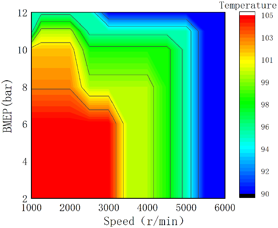
Determination of the best operating temperature for the coolant
Temperature control method of the DB-MCV
The control method of the DB-MCV is shown in Figure 7. The DB-MCV sends the current temperature signal of the ball valve to the ECU through the SEND protocol. Based on the current speed, the engine speed, the load, the coolant temperature, the oil temperature and other information, along with the heat transfer relationships between the different positions in the cooling system, the ECU calculates the target temperature and transmits it to the DB-MCV. Based on the target temperature and the current water temperature, the DB-MCV uses the proportional-integral-derivative (PID) control method to calculate the target angle. Using the current angle value and the target angle value, the duty ratio of the output pulse-width modulated (PWM) wave is determined and is output to the motor after voltage amplification. The ball valve is then operated within 0.5 s to reach the target angle value.35,36,37,38

DB-MCV temperature signal transmission process
Control strategy of the DB-ICS
The DB-ICS is composed of the DB-MCV, a coolant pump, a radiator and other components. The mutual control strategy is illustrated in Figure 8. By correcting the coolant temperature for the previous cycle continuously, the engine’s inlet and outlet coolant temperatures can be controlled accurately to provide more reasonable working temperatures for the engine and the coolant.

Cooling system control strategy
Test methods and equipment
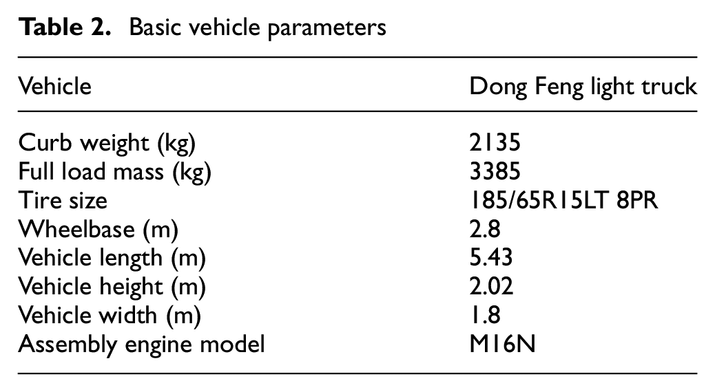
The DB-MCV was assembled on a Dongfeng light truck and a comparison test was carried out with respect to the performance of the traditional thermostat. The vehicle information is shown in Table 2.
Basic vehicle parameters
The experiment used the same test system shown in Figure 9, including the chassis dynamometer, the emission analyzer and the fuel consumption measurement instrument.
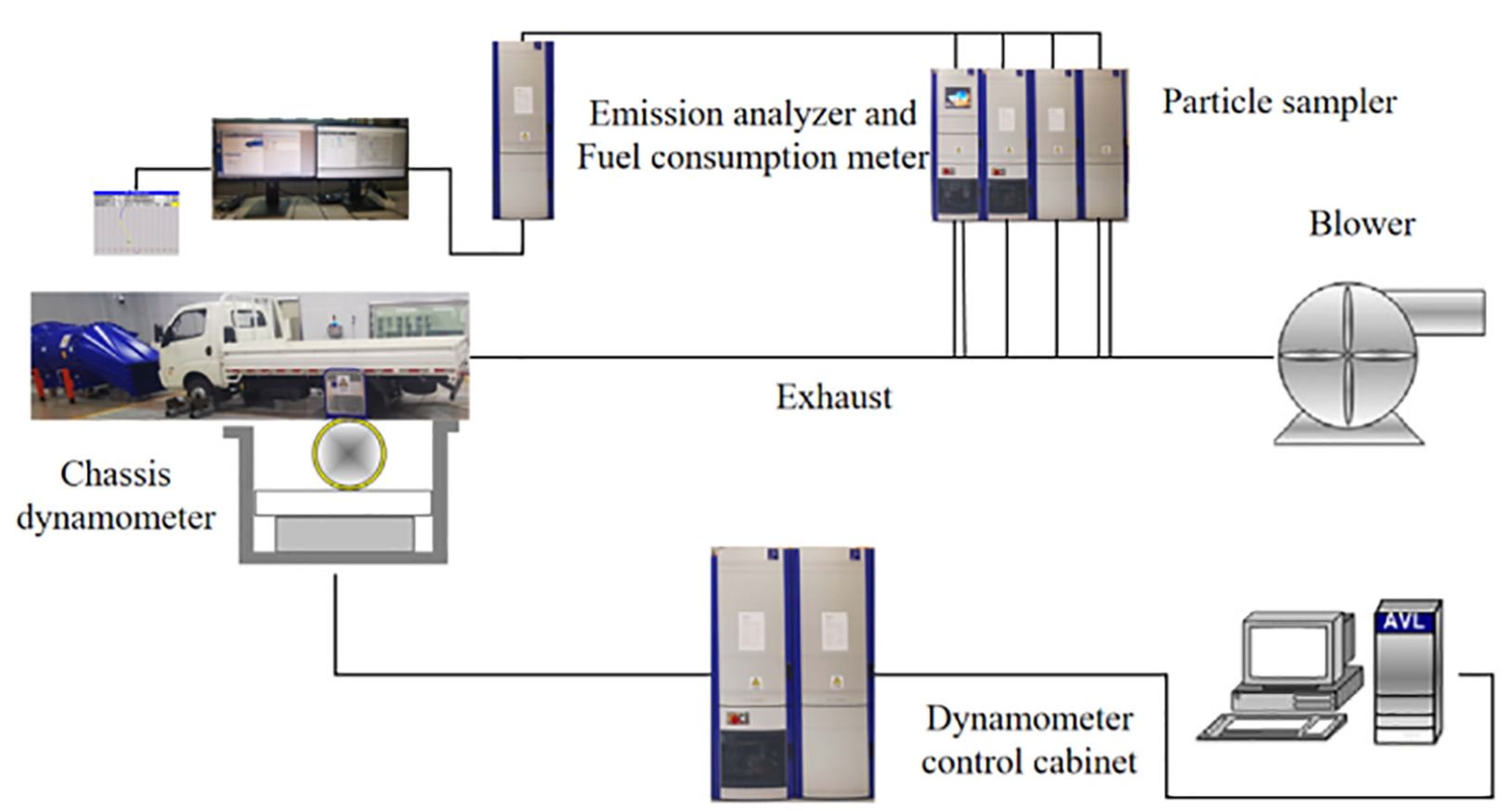
Schematic diagram of the vehicle test system
To ensure the accuracy of the test, AVL equipment was used. The equipment specifications are shown in Table 3.
Test equipment specification sheet

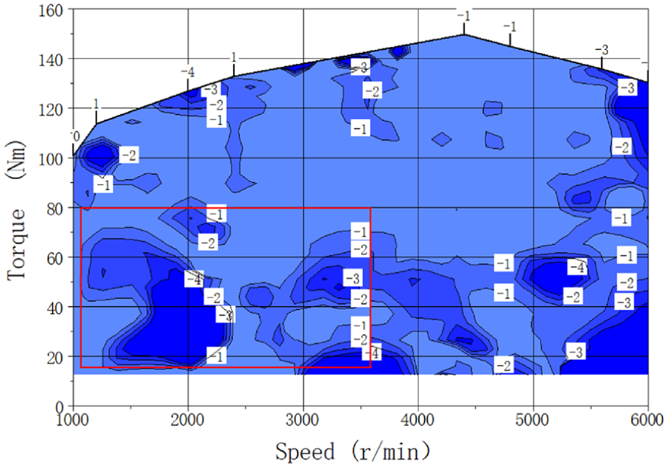
For the vehicle test condition, the Worldwide Harmonized Light Vehicles Test Cycle (WLTC) was adopted, with a total travel distance of 23 km and a cycle period of 1800 s. Analysis of the test data shows that the engine mainly operates at 1000 to 3600 r/min and below a 60% load, as shown in Figure 10.

Load analysis of the WLTC
Test results and discussion
Fuel economy analysis
As shown in Figure 11, the fuel consumption test conducted on the bench shows that, when compared with the traditional thermostat, the fuel consumption of the DB-MCV is reduced by approximately 2% on average under low or medium loads, and the fuel consumption under the highest load conditions (specifically, when the speed is 1500–2000 r/min and the load is 20–60 Nm) can be reduced by 4%.
Comparison of engine fuel consumption characteristic test results
As shown in Figure 12, the fuel consumption comparison tests performed on the same vehicle showed that when compared with the traditional thermostat at engine speeds in the 1000 to 3000 r/min range, the average fuel consumption of the DB-MCV is lower by 2.31%. These results are comparable with those obtained from the bench test. Specifically, when the coolant temperature is 105°C and the load is 1 to 4 bar, the fuel consumption can be reduced by up to 6.5%.

Vehicle fuel consumption test results comparison
Exhaust emission analysis
As shown in Figure 13, based on emission testing of the same vehicle, comparison with the traditional thermostat shows that use of the DB-MCV causes THC emission to be reduced by 6.62%, CO emission to be reduced by 7.25% and NOx emission to be reduced by 4.45%. After installation of a catalytic converter, THC emission was reduced by 6.79%, CO emission was reduced by 7.18% and NOx emission was reduced by 4.84%. Comparison with the effect of addition of the catalytic converter shows that the emission reduction rate for NOx increases, while the emission reduction rates of CO and THC are similar. Note: The emission reduction rate is calculated as (emissionthermostat− emissionDB-MCV)/emissionthermostat×100%.
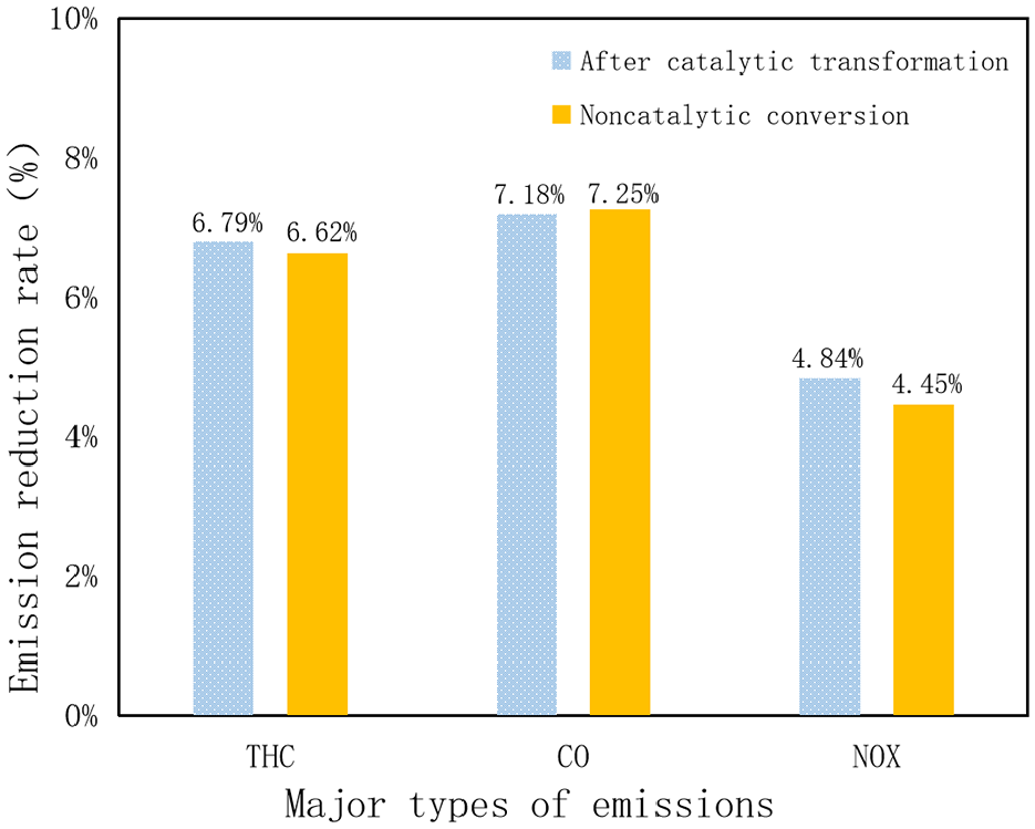
Comparison of vehicle emissions when using mechanical thermostats and DB-MCV
As shown in Figure 14, with regard to the THC and CO emissions in the cold start and preheat phase, the catalytic converter has yet to reach the best ignition temperature, which means that the catalytic conversion efficiency is low. Therefore, before and after addition of the catalytic converter, the THC and CO emission reduction rates remained nearly unchanged. NOx emissions are higher in the cold start and preheat phase and also in the medium and high speed stages, when the high speed conversion efficiency of the catalytic converter is greatly improved. Therefore, after addition of the catalytic converter, the observed reduction in NOx emissions was larger.

Comparison of emission data from mechanical thermostat and DB-MCV in vehicle
As shown in Figure 15, after adoption of the DB-MCV, the engine’s coolant flow rate during the cold start and warm-up phases is zero, which improves the engine warm-up time by 61 s (23°C–80°C at normal temperatures). On the one hand, the engine reaches its operating temperature quickly, thus improving the combustion efficiency and reducing pollutant emissions. On the other hand, increasing the exhaust heating speed can shorten the catalytic converter ignition time, thus improving the conversion efficiency and further reducing the level of pollutants in the exhaust gas.

Comparative analysis of automobile heating conditions
Coolant temperature control
As shown in Figure 16, the coolant in the conventional cooling system flows through the cylinder block and then enters the cylinder head for further heating. Therefore, the cylinder head coolant temperature is higher than the cylinder block coolant temperature by approximately 7°C. The DB-ICS can control the coolant flows in the cylinder block and cylinder head independently, thus keeping the cylinder block and the cylinder head at a higher temperature of approximately 105°C. When compared with the traditional thermostat, the DB-MCV increases the working temperature of the coolant by 15°C and the temperature can be controlled with accuracy of within ±1°C.
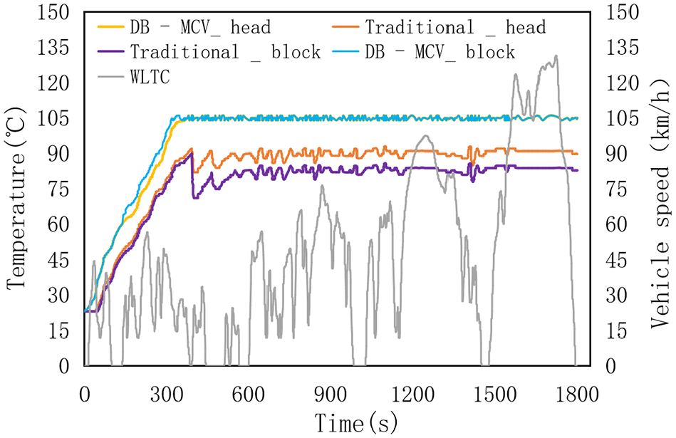
Comparison of vehicle coolant temperature curves
Analysis of passenger cabin comfort
As shown in Figure 17, the temperature information acquired from the cabin seat indicates that the DB-MCV can increase the cabin temperature by 4.3°C when compared with the traditional thermostat, thus improving passenger thermal comfort.

Passenger cabin temperature characteristics during idling
Engine hot dip analysis
Figure 18 shows the coolant temperature characteristics obtained when the vehicle stops after running at a high speed. When a conventional thermostat is used, the coolant in the engine heats up quickly, causing the temperature to increase by approximately 11.4°C. When the DB-MCV is used, all the cooling channels are opened and the coolant temperature in the engine drops rapidly, thus avoiding the risk of hot immersion of the engine and improving the engine’s working stability and reliability.
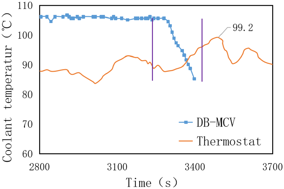
Variations in the engine coolant temperature under idling conditions after high speed running
Conclusion
At present, the linear logic used in profit maximization in the automobile industry leads to a contradiction between the economic benefits and the environmental benefits of technological developments that requires a solution based on mutual support and compensation between the goals of energy conservation and emission reduction. With this background, a control valve composed of a double ball motor was developed and was compared with the traditional cooling system. The following conclusions are drawn:
In this paper, the DB-MCV is used to control the cylinder block, the cylinder head, the oil cooler, the EGR cooler and the large cycle path.
The fuel consumption of the DB-MCV is significantly lower than that of a mechanical thermostat when the engine is under medium and low loads, with an average reduction of approximately 2%. When using the same vehicle under the same working conditions, the average fuel consumption of the DB-MCV is reduced by 2.31% when compared with the conventional thermostat.
Use of the DB-MCV can enable independent control of the coolant flows of the cylinder block and the cylinder head to achieve accurate thermal control; the temperature control accuracy can reach ±1°C, which means that the coolant temperature can be controlled at 105°C to reduce the friction loss and cooling loss.
In the WLTC, the DB-MCV was used to shorten the preheating time by 61 s. The emission of major tailpipe pollutants such as THC, CO and NOx can be reduced by 6.79%, 7.18% and 4.84%, respectively.
When using the DB-MCV, the cabin heating speed is accelerated, the cabin temperature is increased by 4.3°C and the thermal comfort of the passengers is thus improved.
Use of the DB-MCV can effectively prevent the risk of engine thermal soaking caused by parking of vehicles after high-speed operation.
During cold-start preheating, application of the DB-MCV can accelerate preheating of the engine oil. This preheating of the engine oil contributes to the friction loss of the entire machine, but its exact contribution will require further research in the future.
Footnotes
Acknowledgements
The project thanks teacher Yang Chuanlei and students Shi Mingwei and Wang Jing for their support in this work. We also appreciate the support of Dongan Automotive Power Co., Ltd.
Handling Editor: James Baldwin
Declaration of conflicting interests
The author(s) declared no potential conflicts of interest with respect to the research, authorship, and/or publication of this article.
Funding
The author(s) disclosed receipt of the following financial support for the research, authorship, and/or publication of this article: The authors disclose that the research, the authors and the work involved in publishing this article on an intelligent cooling system based on the double-ball motor control valve were supported by Harbin Dongan Automotive Power Co., Ltd.