
Abstract
A novel Injection-rolling Nozzle (IRN) in an imprint system with continuous injection direct rolling (CIDR) for ultra-thin microstructure polymer guide light plates was developed to achieve uniform flow velocity and temperature at the width direction of the cavity exit. A novel IRN cavity was designed. There are eight of feature parameters of cavity were optimized by orthogonal experiments and numerical simulation. Results show that the flow velocity at the width direction of the IRN outlet can reach uniformity, which is far better than that of traditional cavity. The smallest flow velocity difference and temperature difference was 0.6 mm/s and 0.24 K, respectively. The superior performance of the IRN was verified through a CIDR experiment. Several 0.35-mm thick, 340-mm wide, and 10-m long microstructural Polymethyl Methacrylate (PMMA) guide light plates were manufactured. The average filling rates of the microgrooves with the aspect ratio 1:3 reached above 93%. The average light transmittance is 88%.
Keywords
Introduction
The critical requirement for achieving high-throughput production of micro-components is the design of viable manufacturing platforms with cost-effective fabrication. Numerous technologies have been utilized for the mass production of micro-components. Despite the diversity of application areas, the most viable micro fabrication technologies for achieving high-throughput manufacture are different combinations of micro-injection molding and hot imprint processes.
In Lin et al.’s 1 research, a microinjection molding method was present with photo-etched micro-patterns on mold inserts to manufacture a light guide plate with microstructures. The author figured out that low mold temperature increases the plate flatness, whereas high mold temperature improves height replication of the microstructure. Holthusen et al. 2 provided a modified diamond turning process to machine highly functional diffractive microstructures, and the replication of the microstructures and the filling behavior of the mold by injection molding was investigated. However, during the manufacture of ultra-thin microstructure guide light plates, micro-injection molding exhibits high flow hysteresis, It affects the formation accuracy of ultra-thin, large-area microstructure guide light plates. 3
Scholars such as Kolli et al. 4 and Wu et al. 5 have studied the plate-to-plate hot imprint method to achieve microstructures or nanostructures, which has the merits such as high replication rate and low production cost. In addition, various methods have also been applied to the formation of thin film with microstructures, such as hot imprint with roll-to-plate or roll-to-roll, and ultraviolet imprint lithography.6–9 Generally, polymer flat plates are required to be pre-created in advance and reheated before processing in hot imprint technologies, which leads to long production cycle and low production efficiency. Moreover, the microstructure uniformity is difficult to be controlled in hot imprinting processes.
To improve the production accuracy, a novel imprint system with continuous injection direct rolling (CIDR) was developed 10 as shown in Figure 1. The CIDR imprint technology can convert intermittent injection forming into continuous injection forming by fabricating the microstructure continuously, and the microstructure formed can then be hot-imprinted in the rolling zone to ensure the formation accuracy. It also expands the imprint area of a microstructure and minimize cost, which achieves high-throughput production. The detailed principle is also described in Wang et al. 10
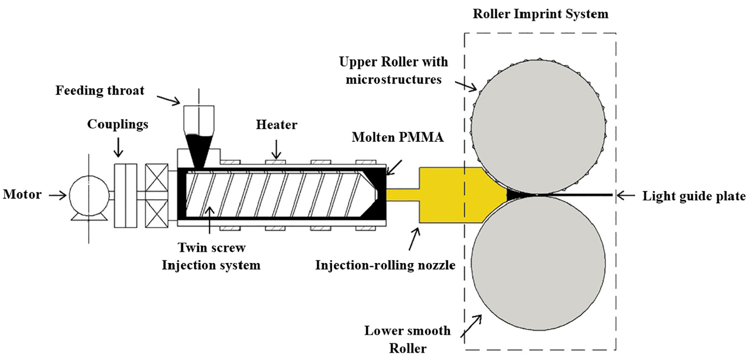
Schematic of the developed CIDR imprint system.
In the CIDR imprint system, the Injection-rolling nozzle (IRN) is the most important component because it connects both the Twin screw injection system and the Roller imprint system. First, melted polymer was injected into the IRN through the Twin screw injection system. Second, the molten material in the IRN was compressed into the Roller imprint system, where it contacts with the upper and lower rollers at a certain injection force. Due to the cooling action from the rollers, the fluid polymer gradually changes from the viscous state to the rubbery state, and finally to the glass state. The microstructure of the upper roller surface was simultaneously duplicated on the polymer surface, and a polymer guide light plate with the desired microstructure was obtained. 11
Numerous studies have been conducted on metal roll-casting nozzle.12,13 Two types of nozzle cavities, French Pechiney of 3C-type horizontal casting machine nozzle cavity and Fata Hunter caster nozzle cavity, are commonly used in the traditional process. However, they cannot be able to satisfy the demands of the ultra-thin, high-speed roll-casting process easily. 14 Beals R 15 and Smith D 16 designed an adjustable feed tip nozzle which can obtain the product with varies thickness and width. Sarioglu K 17 and Sahai and Saxena 18 invented and Sahai and Saxena 18 invented a novel Hunter cavity structure type of roll-casting nozzle. Zhong J. et al. 19 simulated the molten aluminum flow of two different feed tips under either laminar flow model or low Reynolds number k-ε turbulence model using 3-D numerical simulation, which showed that these two feed tips have similar flow at the exit. However, the above literatures are all concerned on metallic materials, instead of polymeric materials. The flow cavity structure needs to maintain the uniformity of velocity at the width direction of the nozzle exit to satisfy the CIDR process requirement. Two types of flow cavities, the fishtail-type and hanger-type structures, are typically used in nozzles. 20 However, normal flow cavity structure of the roll-casting nozzle cannot provide high-quality flow field.
To satisfy the CIDR process for ultra-thin microstructure polymer guide light plates, an IRN with special cavity was developed and optimized to satisfy the requirements of the CIDR process. Orthogonal experiments and numerical simulations were performed to improve the cavity structure of the IRN and investigate its effects on the uniformity of velocity and temperature at the width direction of the nozzle exit. Finally, several 0.35-mm thick, 340-mm wide, and over 10-m long PMMA guide light plates with microstructure were replicated under the optimal structure of the IRN by CIDR.
Mathematical method
IRN physical system
The flow cavity structure was designed as shown in Figure 2. First, the polymer flows into the flow cavity through a circular inlet and out through a high aspect ratio rectangular shape as shown in Figure 2(b). The flow cavity includes a divergent section, a compression section and a shaped section. When the polymer melt flows into the divergent section, the flow velocity is nonlinearly reduced due to the increased flow resistance. Then the molten polymer flows into the compression section. When molten polymer flows into the shaped section, the flow velocity can meet uniformity at the width direction of the nozzle exit, and then flows into the gap between the two rollers of the Roller Imprint System.

Injection-rolling nozzle (IRN): (a) injection-rolling nozzle and (b) schematic diagram of the flow cavity structure.
Governing equations
Molten polymer is in a viscous state when it is in the flow cavity of an IRN, so the fluid flow analysis can be used. In typical fluid analysis, equations that must be considered are the mass conservation equation, the momentum conservation equation, and the energy conservation equation. 21
The equation to describe mass conservation law can be expressed using Equation 1 in rectangular coordinates:

where
The momentum conservation equation can be expressed in rectangular coordinates:

where P is pressure on a micro fluid element,
Energy conservation may not be considered due to the entire process being isothermal flow. It is difficult to solve these two equations, probably impossible, for there are too many parameters in the mass conservation and momentum conservation equations. The equations must be solved based on a hypothesis for a specific engineering problem. The principal problem with IRN design is how to make molten polymer flow through a cavity with a uniform and stable velocity.
Considering the practical process, the following assumptions were made during the development of the nozzle model: (1) the flow is steady and fully developed, (2) the flow is isothermal, (3) no slip exists at the nozzle walls, and (4) mass and inertia forces are ignored.
According to the above hypothesis, the mass conservation equation and the momentum conservation equation can be simplified as follows:


where vx, vy, and vz are the velocity at the x direction, y direction and z direction respectively, η is the viscosity.
Molten polymer is an isothermal and non-Newtonian fluid, so its constitution equation of movement is a power law model:

where
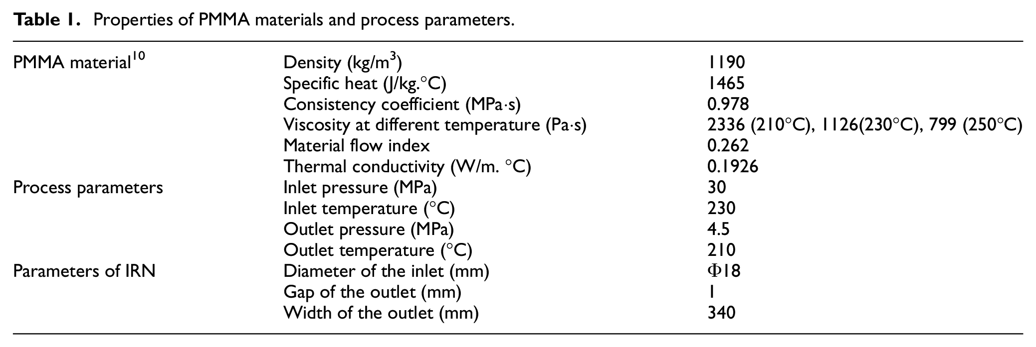
The shear viscosity of PMMA melt was directly measured using a capillary rheometer (RG20, GOTTFERT Corporation, Mount odenlin, Germany) at various inlet temperatures. The measuring data was fitted using the Origin software. The parameters of the equation (5) and the process parameters of CIDR are shown in Table 1.
Properties of PMMA materials and process parameters.
Modeling and condition boundaries
In this paper, the commercial software COMSOL Multiphysics (COMSOL Corporation, Stockholm, Sweden) was employed to simulate the non-Newtonian power law fluid in the IRN. A three-dimension model of the IRN runner was built with software Solidworks (SolidWorks Corporation, Waltham, MA, USA) in advance, and then was imported into software COMSOL to perform meshing operation and simulation calculation. The IRN runner was discretized using tetrahedron elements, and there were 162,261 elements in the whole domain for solving the 3D model.
The diameter of IRN inlet is 20 mm, which must be designed as the same as the outlet diameter of the extruder equipment. The size of the IRN outlet is mainly determined by the size of the final product section. The width and height of IRN outlet are 200 and 1 mm, respectively.
According to the principle of non-slip polymer fluid in the runner, the velocity components are all equal to zero at the interface between the other melt and the runner wall, except for the entrance and exit sections of the runner. According to the process experience of PMMA material extrusion molding, the inlet pressure and outlet pressure of the flow field model are set as 30 and 4.5 MPa, respectively. The temperature of PMMA fluid is set as 220°C at the model inlet. The IRN was equipped with a heating device so that the wall temperature of the runner is set as a constant 220°C. The workstation adopted in this research is equipped with the Intel Xeon(R) E5-2640v4 processor and 64GB running memory. For each simulation, it usually takes 40 min to convergence to steady state on the workstation. The properties of PMMA (CM205, CHIMEI, Taiwan) material used in the model is detailed in Table 1.
Experimental
Materials
PMMA particles (CM205, Chimei Company, Taiwan, China) with a glass transition temperature of 105°C were used as experimental materials. The material properties are shown in Table 1.
Orthogonal experiments
The uniformity of the outlet velocity of the flow can be measured by equation (6).

Where,
In order to optimize the flow cavity of IRN, eight feature parameters which affect the uniformity of the outlet velocity were selected and the range of feature parameters were given based on actual experience (see Figure 3).

The range of feature parameters.
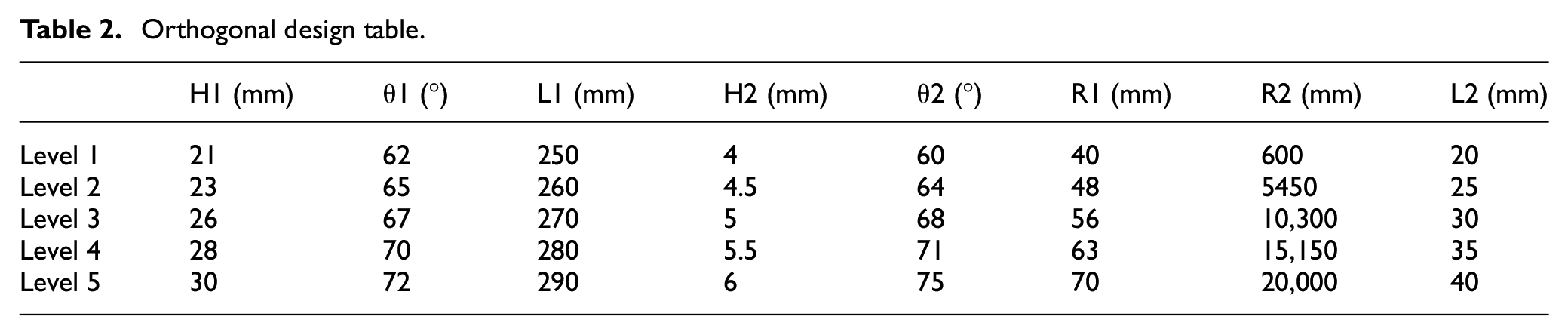
Through orthogonal design, this experiment had eight features and five levels. as shown in Table 2. Then an orthogonal table with L50_5_11 was obtained. It contains 50 sets of tests, and each set of testing parameters represents a different flow cavity. These 50 sets of tests were numerically simulated and analyzed using COMSOL Multiphysics software. The parameters used in the simulation are set according to Table 1.
Orthogonal design table.
Traditional flow cavities experiments
The feature parameters of the hanger-type and the fishtail-type nozzle flow cavity were listed as shown in Table 3 according to their own structural feature. In order to compare with the IRN, the corresponding parameters of flow cavity are consistent with those of the IRN. The numerical simulation of the traditional flow cavity is also conducted by COMSOL Multiphysics software.
The structural feature parameters of Hanger-type and Fishtail-type cavity.

CIDR experiments
The CIDR imprint system shown in Figure 4(a) was fabricated and installed with the optimized IRN. A microstructure was first fabricated on the upper roller surface of the roller imprint system via the Nanotech platform (350UPL, Moore Company, Texas, USA). The microstructure on the surface was of V-groove shaped and presented a roll circumferential layout. The designed depth of the V-grooves is 20, 50, and 80 μm, and the aspect ratio are 1:5, 1:3, and 1:2, respectively. The rolling force can be obtained through the pressure sensor and digital signal processor.
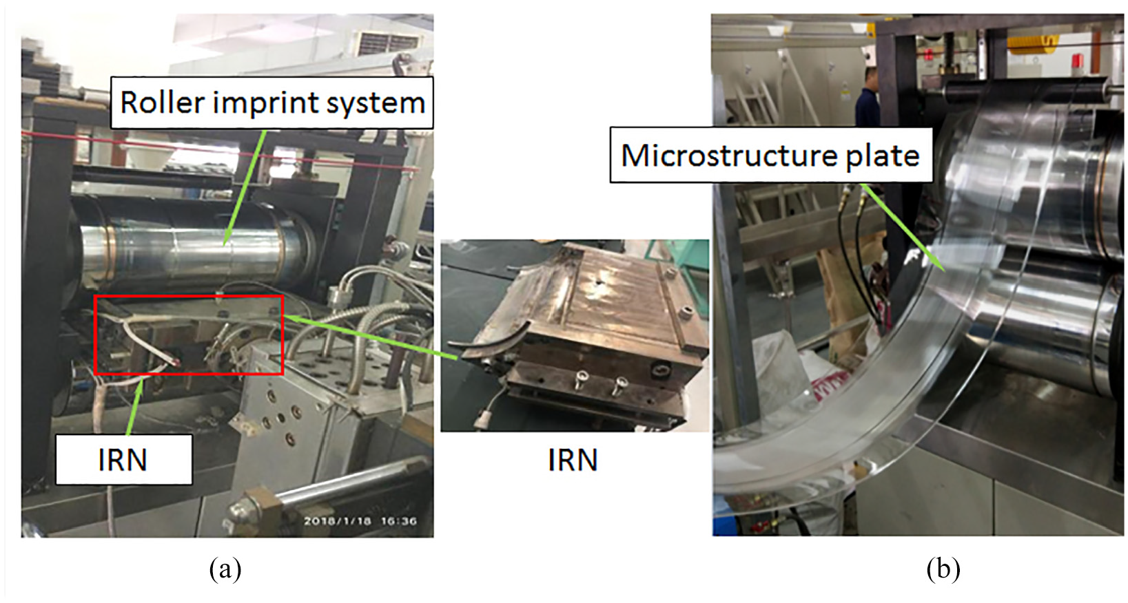
(a) Photograph of the CIDR imprint system and (b) of the microstructure guide light plate.
Figure 4(b) shows the photographs of the manufactured ultra-thin microstructure PMMA guide light plate. The CIDR processes were optimized through a series of CIDR tests, which is consistent with our previous paper in Xiong and Tan. 13 The injection temperature of 210°C, injection pressure of 4.5 MPa, roller velocity of 23 mm/s, rolling force of 13 MPa, and roller temperature of 80°C were selected for experiments. Finally, several 0.35-mm thick, 340-mm wide, and over 10-m long PMMA guide light plates with microstructure were manufactured.
Measurement of the PMMA guide light plate
In this research, each data point is the average value of five to seven measurements on five samples.
Measurement of thickness
The spiral micrometer (SMOT, Shanghai measuring tool factory, Shanghai, China) was used to measure the thickness of ultra-thin microstructural guide light plates. Guide light plates (width 300 mm, length 1000 mm) with non-optimized IRN and optimized IRN were selected, respectively. Then, multiple points at intervals of 15 and 50 mm in the width and length directions were picked, respectively.
Measurement of microgroove
A Lext confocal microscope (OLS4000, Olympus Company, Osaka, Japan) was used to measure the depth of the microstructure of V-groove. The designed depth of the V-grooves is 20, 50, and 80 μm, and the aspect ratio are 1:5, 1:3, and 1:2, respectively. Filling rate = DA/DR × 100%, where DA is the actual average microgroove depth on PMMA, and DR is the designed microstructure depth.
Measurement of optical
Samples of 120 mm in width and 500 mm in length were selected. Multiple points at intervals of 40 and 50 mm in the width and length directions were picked, respectively. The light transmittance of the sheet was measured using a spectrometer (QE65 Pro, Ocean Optics, Florida, USA).
The haze measured by a haze meter (WGT-S, Shanghai precision instrument LTD, Shanghai, China), and the birefringence of the optical sheet was measured by a stress birefringence meter (WYL-4, Shanghai Lengguang technology LTD, Shanghai, China). The measuring points were taken at intervals of 60 mm in the width direction.
Results and discussion
Outlet velocity difference
Non-optimized IRN
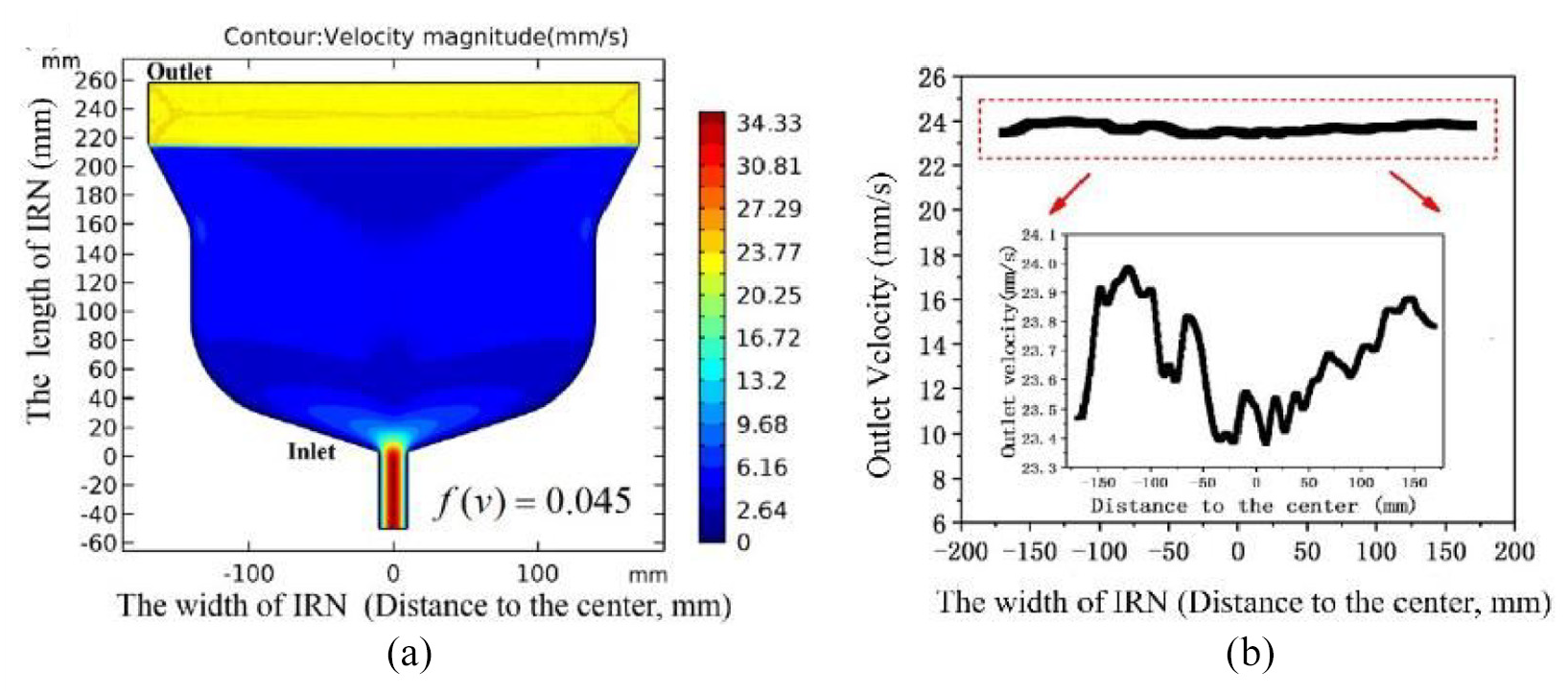
The velocity cloud diagrams of the non-optimized IRN nozzle are shown in Figure 5. The speed distribution on nozzle outlet should be uniform in the width direction, in order to obtain a light guide plate with uniform thickness. The outlet velocity increases first and then decreases from the middle to the both sides. It can be seen that the speed is only 23.5 mm/s in the middle of the outlet, while the maximum speed is on both sides of the outlet reaching to 39.5 mm/s. The maximum difference of outlet velocity is approximately 16 mm/s at the width direction, which obviously cannot meet the technological requirements of continuous injection and rolling. Therefore, it is very necessary to optimize the runner of the injection-rolling nozzle so that its exit speed is as consistent as possible.

Simulation results of the non-optimized IRN: (a) velocity contour and (b) outlet velocity.
Optimized IRN
The impact degree of each feature parameters on the outlet velocity was obtained after orthogonal experiments. It can be seen that the feature parameters of L2 exhibit the biggest influence, those of R2 is the second, and those of the other six parameters are least which are basically negligible. In addition, the value of
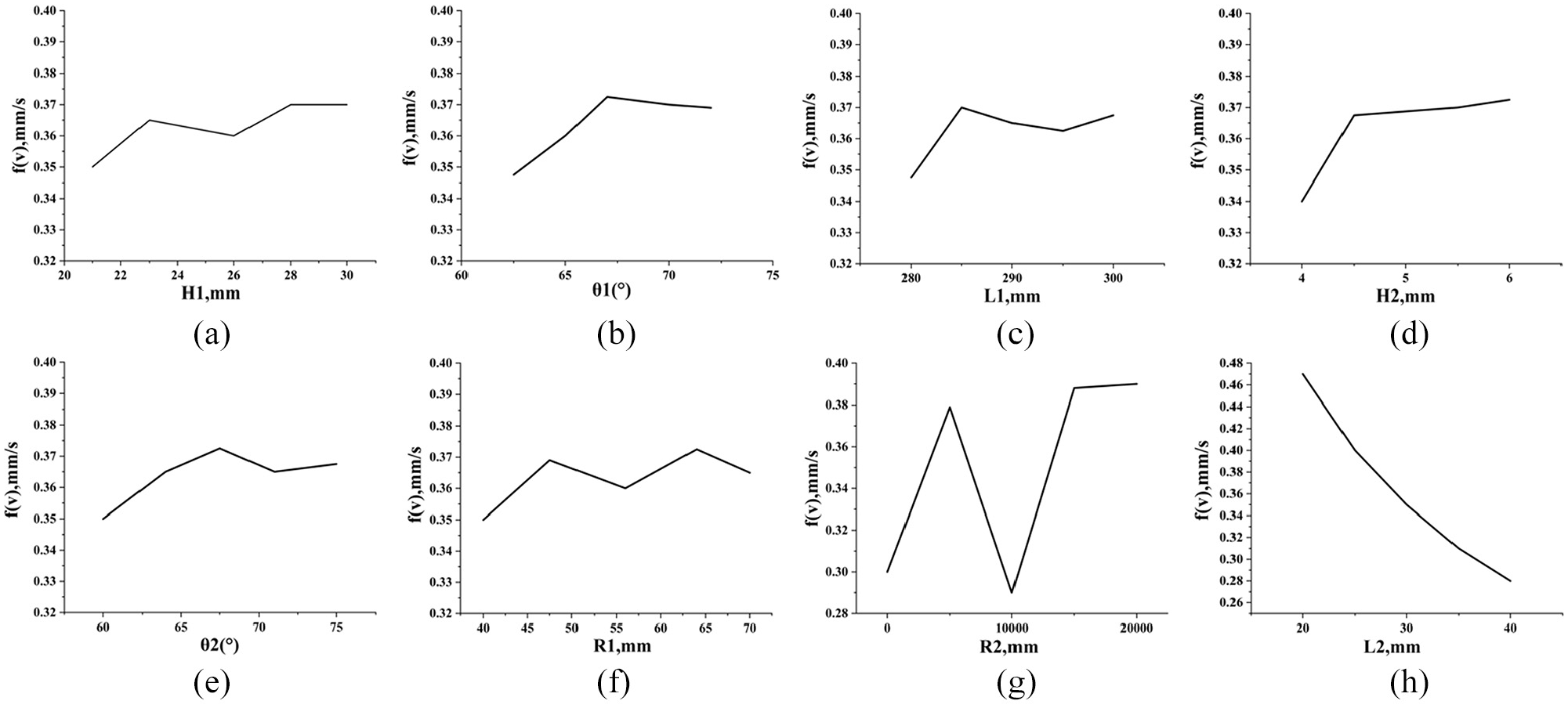
Relationship between various parameters and f(v): (a) H1, (b) θ1, (c) L1, (d) H2, (e) θ2, (f) R1, (g) R2, and (h) L2.
Therefore, the best feature parameters of the flow cavity can be obtained, that is, H1, θ1, L1, H2, θ2, R1, R2, and L2 is 21 mm, 62°, 280 mm, 4 mm, 60°, 40 mm, 10,300 mm, and 40 mm, respectively.
Then the optimal flow cavity is designed as shown in Figure 7, and the velocity contour and the outlet velocity are obtained. It can be seen that the outlet velocity of IRN after optimized is much more uniform than that of IRN before optimized. The value of
Simulation results of the optimized IRN: (a) velocity contour and (b) outlet velocity.
After comparing optimized IRN with non-optimized IRN, the optimized structure has a more uniform velocity contour and a smaller outlet velocity difference.
Pressure and temperature analysis
The pressure contours (in Figure 8(a)) shows that the pressure distribution in the divergent section is relatively uniform. On approaching the characteristic structure R2 where of the compression section, the pressure is stepped which generates back pressure. When the polymer melt enters the shaped section, the pressure distribution is gradually stabilized along the L2 direction, and finally achieved the requirements of CIDR.

(a) Pressure contour and (b) temperature difference at different section.
According to the distribution of pressure in Figure 8(a), four planes (z0, z1, z2, and z3) are created, and the temperature changes on each plane are shown Figure 8(b). It can be seen that the temperature in the middle is higher than both sides, because the fluid in the middle nozzle is facing the inlet of the flow cavity and the heat source is replenished in time. Moreover, as the distance between the selected plane and the outlet decreases, the overall temperature of the plane also decreases. Although the initial temperature of the PMMA melt and the temperature of the IRN runner are both set to 493 K, the melt will exchange and radiate heat with the external environment at the outlet, which leads to the melt temperature gradually decreasing as the melt flows to the outlet. The average temperature on the plane z0 is very close to the initial temperature (493 K), and the melt temperature drops to 486.7 K near the outlet (plane z3). So it can be induced that the degree of heat loss is not severe for a small temperature difference between z0 and z3.
The temperature differences are
Comparison between the IRN and the traditional flow cavities
The outlet velocity of the traditional flow cavity is shown in Figure 9(a) and (b). In order to compare with the IRN, the corresponding parameters of flow cavity (see Table 3) are consistent with those of the optimized IRN. These are 62°, 60°, 40 mm, 10,300 mm, and 21 mm for θ1, θ2, L2, R2, and H1, respectively.

(a) Outlet velocity at the width direction of Hanger-type nozzle and (b) outlet velocity at the width direction of Fishtail-type nozzle.
It can be seen that the outlet velocity difference of the hanger-type reaches 10 mm/s, and the fishtail-type has a velocity difference of 1.5 mm/s. Compared with the two traditional flow cavities, the flow cavity of IRN has a far more uniform velocity distribution on the exit (the outlet velocity difference only reaches 0.6 mm/s, see Figure 7(b)).
Measurement results of the PMMA guide light plate
Thickness of PMMA guide light plate
The error values of non-optimized guide light plate are 0.10 mm at the width direction and 0.09 mm at the length direction as shown in Figure 10(a)). Correspondingly, the error values of optimized guide light plate are 0.04 mm at the width direction and 0.03 mm at the length direction. Therefore, the optimized guide light plate thickness is more uniform, and more suitable for the requirements of the optical sheet (as shown in Figure 10(b)).

Thickness of guide light plate: (a) guide light plate of non-optimized IRN and (b) guide light plate of optimized IRN.
Microgroove of PMMA guide light plate
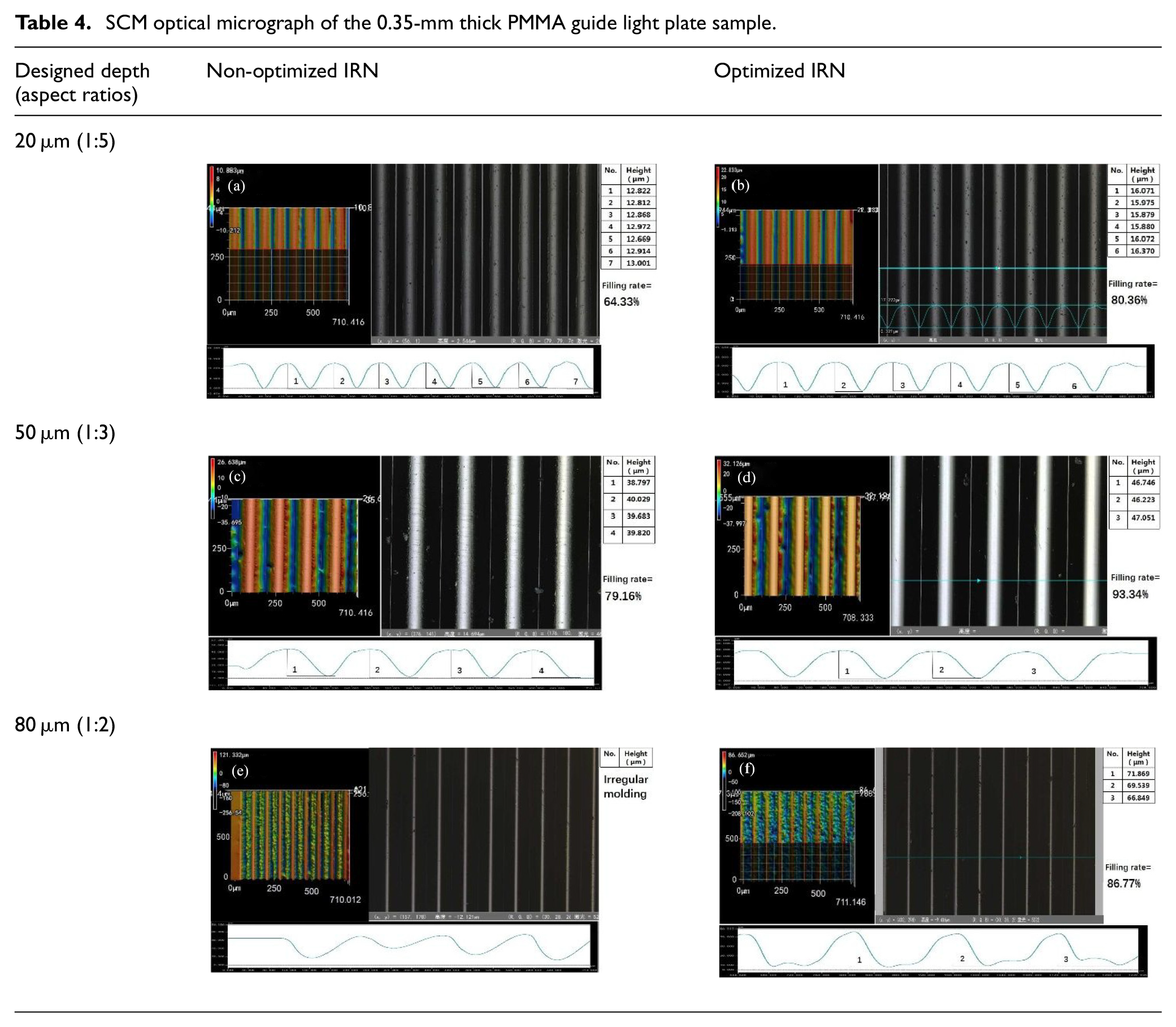
The depth of the microgrooves on the PMMA guide light plate are shown in Table 3. It can be seen that the average filling rates of microstructures are 64.33%, 79.16% and irregular molding with aspect ratios of 1:5 (designed depth of 20 μm), 1:3 (designed depth of 50 μm), and 1:2 (designed depth of 80 μm), respectively, before the IRN was optimized. After the IRN was optimized, the average filling rates of microstructures are 80.36%, 93.34%, and 86.77% with aspect ratios of 1:5 (designed depth of 20 μm), 1:3 (designed depth of 50 μm), and 1:2 (designed depth of 80 μm), respectively. It is very obviously that the filling rate increased after the IRN was optimized. The filling rate of microgroove with aspect ratios of 1:3 (designed depth of 50 μm) is the best. The filling rate of aspect ratio of 1:2 is low, which is mainly due to its depth of V-groove. It is so deep that the melt cannot be filled well, see Table 4.
SCM optical micrograph of the 0.35-mm thick PMMA guide light plate sample.
Optical properties of PMMA guide light plate
The comparison of optical characteristics of the light guide plate produced with non-optimized IRN and optimized IRN is shown in Table 5. Error bars were calculated from the standard deviation for five to seven measurements at each data point. As shown in Table 5, the average values of light transmittance are 81% to non-optimization and 88% to optimization, respectively. It is also found that the uniformity of light transmission of the optimized guide light plate is higher than that of the non-optimized guide light plate. The haze is 0.786% to non-optimization while 0.510% to optimization. For the uniformity of haze, the optimized guide light plate is also higher than the non-optimization.
Optical results of PMMA guide light plate sample.

The value birefringence on both sides of light guide plate are similar in range of 84–86 nm, whether the IRN is optimized. The maximum value of birefringence appears in the center of the plate, and is 107 and 95 nm with a non-optimal IRN and an optimal IRN, respectively. The birefringence value of optimized guide light plate is acceptable in optical lens. 22 The birefringence value at the center of the light guide plate is significantly reduced after optimizing the IRN. The shear rate decreases at the center of plate due to the velocity and pressure uniformity after optimizing the IRN. 23 As a result, the residual stress of the plate center decreases, which leads to a lower birefringence value. Therefore, the optimized operation of the IRN has improved the optical quality of the light guide plate.
Conclusion
The novel IRN exhibits better qualities than that of the traditional metal roll-casting nozzle, and the following conclusions were summarized.
A novel flow cavity structure of the IRN was designed, and the IRN finite element model was built in the flow field to analyze the effect of IRN feather parameters on
The difference of outlet velocity and the temperature for the optimized IRN are 0.6 mm/s and 0.24 K, respectively, which can well satisfy the process of CIDR. The pressure step of the IRN is related to the end structure R2 of the compression section, and the pressure distribution along the L2 direction is more and more uniform.
Several 0.35-mm thick, 340-mm wide, and over 10-m long PMMA guide light plates with microstructure were fabricated by the CIDR process of IRN. The average filling rates of the microgrooves with the aspect ratio 1:3 (designed depth of 50 μm) reaches above 93%. The guide light plate after optimized IRN which light transmittance is 88%, the haze is 0.51%, and the maximum stress birefringence detection is 95 nm. The guide light plate meets the requirements of optical elements.
The replication results indicate that the novel IRN satisfies the CIDR imprint system requirements, and it is potentially suitable for fabricating various ultra-thin optical microdevices such as guide light plates, etc.
Footnotes
Handling Editor: James Baldwin
Declaration of conflicting interests
The author(s) declared no potential conflicts of interest with respect to the research, authorship, and/or publication of this article.
Funding
The author(s) disclosed receipt of the following financial support for the research, authorship, and/or publication of this article: The authors gratefully acknowledge research support from the National Natural Science Foundation of China (No. 52075342, 51675347).