
Abstract
Permanent magnet linear motors can cause thrust fluctuation due to cogging and end effects, which will affect the operation stability of the linear motor. In order to solve this problem, a new method of eliminating alveolar force by using phase-shifting and displacement is proposed in this paper. Taking the cylindrical permanent magnet linear motor as an example, the traditional cylindrical permanent magnet linear motor is divided into two unit-motors, and established finite element analysis model of cylindrical permanent magnet linear motor. It is different from other traditional methods, the thrust fluctuation was reduced by both phase-shifting and displacement simultaneously in this paper, and through simulation analysis, it is determined that the thrust fluctuation suppression effect was the best when the cogging distance was shifted by half. Furthermore, a comparative simulation was made on whether the magnetic insulating material was used. The simulation results show that: The method proposed in this paper can effectively suppress the thrust fluctuation of the cylindrical permanent magnet linear motor. And it can be applied to other similar motor designs. Compared with the traditional method of suppressing thrust fluctuation, the mechanical structure and the technological process of suppressing thrust fluctuation used in this method are simpler.
Introduction
Linear motors have been playing an increasingly important role in recent decades. Its advantage over rotary electric machines lies in the absence of any intermediate mechanism of an electromagnetic transmission switching device, but a device that directly converts electrical energy into mechanical motion. Consequently, the device has a wide range of applications. Permanent magnet linear synchronous motor has the dual advantages of permanent magnet motor and linear motor. Its small size, fast response, and simple structure make it have wide application prospects.1–3 However, due to the cogging effect and the end effect of the linear motor, the thrust fluctuates of the linear motor greatly, which affects the performance of the linear motor and cannot be applied to some occasions with high precision requirements. Thus must take measures to suppress the fluctuation of the thrust force of the linear motor.4–8
At present, scholars all over the world have done a lot of work to suppress the thrust fluctuation of a permanent magnet linear motor, but the main scope of work is still limited to the following aspects. Such as gear cutting processing of the motor, 9 changing the width of the motor end cogging, 10 adoption of semi-closed slot, changing the pole arc coefficient, 11 optimizing the primary length, opening the auxiliary slot, 12 adoption of stator skew, and suppression of thrust fluctuation from control strategy etc. There is no method to suppress the motor thrust simultaneously in terms of phase-shifting and displacement.
Zhao et al. 13 of the Shenyang University of Technology discusses the effect of different measures on suppression of motor thrust fluctuation. For example, the no-load thrust fluctuation of the motor is reduced by 30% in literature by changing the primary length of the linear motor, and the thrust fluctuation of this motor is reduced by 19% by optimizing the pole arc coefficient. Furthermore, the motor’s thrust fluctuation is reduced by 32% by optimizing the slot geometry; Shi 14 of Harbin Institute of Technology combined several solutions through the optimization of the radial length of the edge-end cogging, the optimization of the axial width of the edge-end cogging, the optimization of the additional edge-end cogging external magnetic guide, and the optimization of the ratio of pole slots, and finally reduced the thrust fluctuation of the seven-slot six-pole linear motor from 37.9% to 11.6%, which is a relative reduction of 69.3%. Sun et al. 15 analyzed the permanent magnet synchronous motor with a specific drive cycle of the electric vehicle, optimized the permanent magnet structure, air gap length, and stator core geometry, and reduced the torque ripple by 24%; Besides, they have proposed a highly efficient three-level optimization for interior permanent magnet synchronous motors (IPMSM), enabling the motor to achieve smaller torque ripple and lower power loss; 16 Liang et al. 17 proposed a grid on/off search method for rotor profile and improved the design to reduce the torque ripple of the motor; Gonzalez-Palomino et al. 18 optimized the stator skew method and reduced the thrust fluctuation of PMLSM by 54.1%. It can be seen that each optimization scheme can suppress the thrust fluctuation to a certain extent, but the inhibitory effect of a single optimization scheme is weak. In practice, a combination of multiple schemes is usually used to effectively suppress the thrust fluctuation of linear motors.
This paper proposes the method of phase-shifting and displacement simultaneously of the unit-motor. Taking an integer slot linear motor as an example, it was divided into two unit-motors, and the validity of the method was analyzed by software modeling. The simulation results show that this method can effectively suppress the thrust fluctuation of the permanent magnet linear motor. Compared with the existing schemes, this method has a better suppression effect on the thrust fluctuation of the linear motor, and even better than the combination of some programs. The optimized integer slot linear motor can also be combined with other traditional optimization solutions to further reduce the thrust fluctuation of the linear motor. Therefore, this method is of great significance for improving the stability of linear motor operation.
Analysis of principles of eliminating cogging force in series of unit motors
The principle and mathematical model of the cogging force of linear motors is analyzed below. According to characteristics of the linear motor, the principle of superposition and elimination of the cogging force of the unit motor is derived.
The principle of cogging force generation in the linear motor
The permanent magnet linear motor is the same as the rotary motor and has a slot structure formed inside. Due to the presence of the slot, the air gap magnetic permeability between the primary and secondary iron core changes, so that the interaction force also changes. Eventually, the cogging force causes the Linear motor thrust fluctuations. The variation of air gap conductance of permanent magnet linear motor is shown in Figure 1. It can be seen from Figure 1(a), λ1 < λ2, two different magnetic flux paths lead to different magnetic reluctance. When the primary or secondary iron core of the linear motor moves linearly, the relative position of the linear motor constantly changes, leading to the continuous change of the air gap magnetic permeability, and therefore a cogging force is generated. If the primary core has no slots, the magnetic conductance of the two magnetic circuits is constant. As shown in Figure 1(b), λ1 = λ2, the energy stored in the magnetic field does not change, and the interaction force between the primary and the secondary iron core does not change, so that the cogging force can be eliminated. However, in practice, the armature core of the permanent magnet linear motor has different shapes of the cogging slots to insert winding wires, so that the cogging force cannot be eliminated and only certain measures can be taken to weaken it.19–22

The air gap magnetic conductance.
Mathematical model of the cogging force of the linear motor
The cogging torque of a rotating permanent magnet motor is defined as the negative derivative of the internal magnetic co-energizer W concerning the position angle α, 23 which is

Permanent magnet linear motors can be considered as an evolution of rotating permanent magnet motors. Therefore, the magnetic field energy calculation of rotating permanent magnet motors is also applicable to linear motors. The displacement of the primary and secondary core of the permanent magnet linear motor along the direction of motion corresponds to the offset angle in the rotating motor. So, the cogging force of the linear motor is defined as

The motor will produce cogging force even the armature winding of permanent magnet linear motor does not energize, which is related only to the relative positions of the primary and secondary. The cogging force generated by each permanent magnet in a linear motor can be represented by the Fourier series. For the i-th permanent magnet, the cogging force is:

Where k is the number of harmonics, k = 1,2,3,…,

In the formula,
Formula (4) into the type (3), p is the number of pole pairs, and the total cogging force is a superposition of the cogging forces generated by 2p magnetic poles:

It can be
The principle of phase shift and displacement superposition elimination of cogging force
From formula (5) we can see that the total motor cogging force is obtained by superposing the cogging force generated by 2p magnetic poles for the integer slotted linear motor. Assuming that the cogging force generated by each magnetic pole is a sinusoidal function with periodic cogging spacing, the total cogging force is the superposition of all sinusoidal functions with the same phase and amplitude, as shown in Figure 2.

Tooth slot force of traditional motor.
Based on this phenomenon, this paper proposes the principle of cogging force phase-shifting and displacement superposition. That is, if there are two motors with the same cogging force amplitude and opposite phases, theoretically, the crests and troughs of the two sine functions will cancel each other, and the cogging force can be completely suppressed, as shown in Figure 3. However, in reality, the cogging force is not likely to be a sine function, and the cogging force generated by each magnetic pole is also slightly different. So, it is impossible to completely cancel the cogging force, but it is feasible to reduce the cogging force.

Tooth groove force of unit motor in series.
Since the cogging force generated by each pole is periodic with cogging spacing, assuming a cogging spacing of 10 mm, the mathematical model of the cogging force can be as shown in Figure 4. It can be seen that no matter what type of cogging force is shown in the table, shifting the second set of cogging force to the right by 5 mm in space can make the crest and trough opposite to produce an offset effect, and it can be seen that the offset effect is best when the ideal model is moved by 5 mm. Although there is a certain offset in the peak point of the cogging force of the actual motor, it is almost always near the peak point of the above ideal model.

The cogging force of the actual situation.
From the above analysis, it can be seen that two motors with the same slot will offset some of the cogging force if the motor’s cogging force displace in space. From Figure 4, it is seen that the offset effect of the shift half of the gear is the best, but the initial angle of the two motors changes after the unit motor displace, which will lead to the uneven output of the two motors in the actual motor operation. Therefore, the two-unit motors must shift in time while shifting in space. The Angle of the shift in time depends on the percentage of the shift length in the polar distance. Assuming that the space shift length is t and the pole pitch of the motor is T, the unit motor that moves in space must also move the phase by t/T × 180° in time to ensure that the initial working angle of the two-unit motor is the same. At the same time, achieve the effect of inhibiting the cogging force.
The effect of suppressing the cogging force by using two-unit motors or more than unit motors in phase shifting is different. This paper mainly analyzes the method of suppressing the cogging force by two-unit motors in series phase-shifting. And the principle of series phase shifting of multiple unit motors is the same as this.
Finite element model and parameters of two-unit motors in series
In the previous section, the principle of eliminating the superposition of multiple cogging forces has been analyzed. The following is verified by the simulation to verify the correctness of this principle. To make the results comparable, all the following simulations are the same except for the differences in structure. This paper uses an integer slot linear motor as an example to analyze and verify this method.
Simulation analysis of traditional linear motors
Finite element analysis is a simulation process in which the practical problem is mathematized and the approximate solution is obtained. The essence is to simplify the problem and the modeling steps are shown in Figure 5.

Modeling steps.
This paper establishes the finite element analysis model. The main parameters of the linear motor are shown in Table 1:
Parameters of permanent magnet linear motor.

The model of a cylindrical linear motor built from the data in the table is shown in Figure 6:
Traditional linear motor simulation model.
When the linear motor does not add the excitation source, the curve of the relationship between the stress of the rotor of the motor and the time by solving the calculation is shown in Figure 7. There is no current flowing through the motor coil. At this time, the no-load thrust fluctuation of the motor is attributed to the cogging force and the end force of the motor.

The thrust curve of the motor when the traditional linear motor is not excited.
When current excitation is applied, the added three-phase excitation is

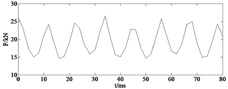
The thrust curve of a traditional linear motor plus excitation.
As can be seen from Figure 7, when the excitation source is not applied, the thrust of the motor fluctuates between −2.7 and 2.7 kN due to the action of the cogging groove force and the end force. It can be seen from Figure 8, after adding the excitation source, the motor thrust fluctuates around 20 kN, the minimum force is 15 kN, the maximum force is 25 kN, and the thrust fluctuation is 50%.
Simulation analysis of two unit motors in series
In the above, a model of a conventional linear motor was established, and the thrust fluctuation range of the excitation source and the non-excitation source was analyzed. In the following, the motor is divided into two unit-motors without phase-shifting. That is, the interval was an integer multiple of the pole distance, and then the thrust fluctuation range is analyzed. To avoid the electromagnetic interference generated by the two unit-motors, a magnetic insulation material is added between the two units of the motor. Finally, the pitch of the adjacent cogging of the two unit-motor is 6.4 mm. The established motor model is shown in the Figure 9.

Unit motor model.
The curve of the relationship between the force of the rotor of the motor and the time of the above model when no excitation source is added is shown in Figure 10. When the current excitation is added, the curve of the relationship between the force of the rotor of the motor and the time is shown in Figure 11.

Motor’s thrust curve when the unit motor is not excited.
Motor’s thrust curve when unit motor is energized.
As can be seen from Figure 10, when the excitation source is not applied, the thrust of the motor fluctuates between −2.5 and 2.5 kN due to the action of the cogging groove force and the end force. As can be seen from Figure 11, after the excitation source is added, the motor thrust fluctuates around 20 kN, the minimum force is 15 kN, the maximum force is 25 kN, and the thrust fluctuation is 50%.
From the above data, it can be seen that the ordinary motor is split into two unit-motors, and the phase-shifting process is not performed, the thrust fluctuation will not change substantially. This also proves that the disassembled two-unit motor in this paper is completely equivalent to the original motor, that is, the subsequent adjustment analysis is completely comparable to the original motor.
Comparison and analysis of series phase shift of two-unit motors
The following uses the method of series motor phase-shifting and displacement simultaneously to optimize the traditional integer slot permanent magnet linear motor, and study changes in motor thrust fluctuations.
Optimum shift distance after connecting two-unit motors in series
Ideally, the cogging force of the two-unit motor is a standard sine wave, so shifting half the cogging space is the best counteracting of the cogging force. But from the above analysis can be seen that there will be a certain offset between the actual thrust peak value and valley value. Therefore, it is necessary to analyze and calculate the optimal displacement distance after the series connection of the two-unit motor.
Using the motor model in Figure 11, only the thrust of one unit-motor is calculated and the thrust output curve is shown in Figure 12.
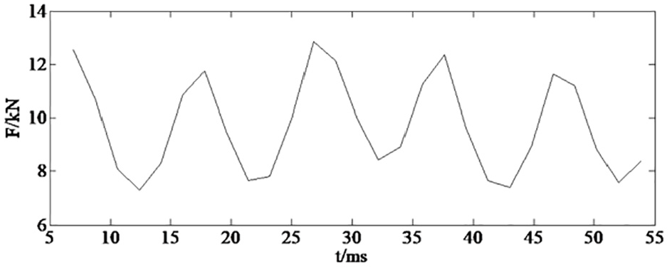
Thrust curve of a unit motor.
The force fluctuation of two units after the series connection is analyzed below. The waveform of Figure 12 shifts a certain distance and superimposed with the original waveform, and the result is the waveform of the force after the two-unit motors are shifted in series. Shift the waveform to 1–10 mm, respectively, find the peak of the superposition curve, take the moving displacement as the transverse coordinate, the corresponding peak as the ordinate, and make the curve as shown in Figure 13.

The curve of moving displacement and thrust peak.
It can be seen from Figure 13 that the lowest point of thrust fluctuation after thrust stacking is about the value of the point of 5.4 mm. However, the thrust peak at this point is the same as the thrust peak at 5 mm, and this effect can be ignored. For the convenience of calculation, the following simulation takes the displacement distance as half of the cogging distance, that is, 5 mm.
Simulation analysis of magnetic separators in unit motor joints
The original motor is now split into two identical size unit motors. Because the motor has a 4 mm cogging width and a 6 mm groove width, and according to the previous analysis, we choose to shift the two units by 5 mm. Simulate and analyze the effect of displacement on the suppression of thrust fluctuation.
Simply shifting the two unit-motors will result in different initial phase angles of the two motors, thus resulting in the non-uniform output of the two motors. Therefore, the phase of the excitation must be changed at the same time as the shift.
Since the pole distance of the linear motor is 30 mm, and the two motors are shifted by 5 mm. It can be calculated from the formula that the phase of the shifted unit motor will change 180/30 × 5 = 30°.
The excitation source for the displacement unit motor is:
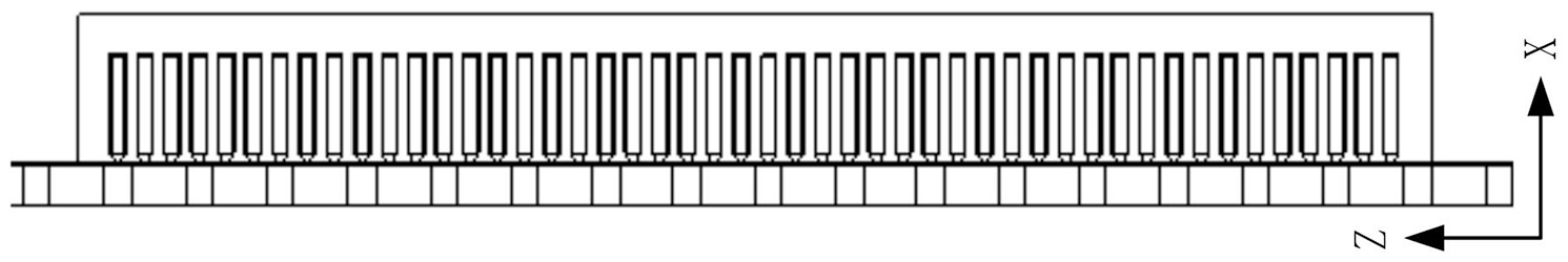
To avoid the electromagnetic interference of the two unit-motor, a magnetic insulation material is added between the two unit-motors. To make the magnetic isolation effect better, the magnetic isolation material is added with the length of double pole distance based on the shift. The simulation model is shown in Figure 14 below.

Unit motor series model with magnetic isolation material.
In the simulation model in Figure 14, the thrust changes in the two cases without excitation source and excitation source are shown in Figures 15 and 16.

The thrust curve of the motor with magnetic insulation material and no excitation.

The thrust curve of the motor when the magnetic material is added and the excitation is added.
It can be seen from Figure 15 that, in the model with two unit-motors in series and magnetic insulation material in the middle, the thrust fluctuates between −0.6 and 0.6 kN without the excitation source. The thrust fluctuation range is significantly reduced compared with that of −2.7 and 2.7 kN in the original structure, which proves that this method has a good suppression effect on the cogging force of the motor.
It can be seen from Figure 16 that the thrust force of the unit motor series model with the excitation source fluctuates from 18.2 to 20.5 kN. The stable output force is about 19.5 kN, and the thrust fluctuation range is 11.7%. Compared with the traditional structure motor, the fluctuation range of 50% is reduced by 76.6%, which is more significant than the method of suppressing thrust fluctuation in literature Cui et al. 8 and Du 9 .
Simulation analysis of non-magnetic insulation material in the unit motor joint
The presence of a magnetically shielded material can reduce the electromagnetic influence of the two-unit motor, but the magnetic insulation material will increase the volume and weight of the dual-unit motor structure and increase the cost. Therefore, the following discusses the case of omitting the magnetic insulation material and connecting the stator cores of the two-unit motor. That is, the cogging width of the connecting portion of the two-unit motor is increased by 5 mm, and the cogging slot width of 1/2 is shifted directly. Its structure is shown in Figure 17.

Unit motor series model without magnetic insulation material.
In the simulation model of Figure 17, the thrust changes of the simulation model with and without excitation source are shown in Figures 18 and 19:

Thrust curve of the motor without magnetic insulation material and no excitation.

The thrust curve of the motor when no magnetic material is added and the excitation is added.
It can be seen from Figure 18 that in the model where two-unit motors are connected in series and no magnetic isolation material is added in the middle, the thrust fluctuates between −1.25 and 1.25 kN without the excitation source. Compared with the non-excited source in the conventional structure, the thrust fluctuation range decreases. As can be seen from Figure 19, the thrust after adding the excitation fluctuates between 18.2 and 21 kN, the stable output force is approximately 19.5 kN, the thrust fluctuation range is 14.3%, compared with the thrust fluctuation of a conventional structure motor, the thrust fluctuation is also significantly reduced.
Visible, even without magnetic isolation material, the use of the two-unit motor shift displacement method can significantly reduce the thrust fluctuation, although the effect is less than the use of magnetic isolation material, but can effectively reduce the size and weight of the motor, the cost is also lower.
Comparative analysis of several situations
The simulation of several models of motor structures was performed above. The following simulation results and data are summarized in the following table.
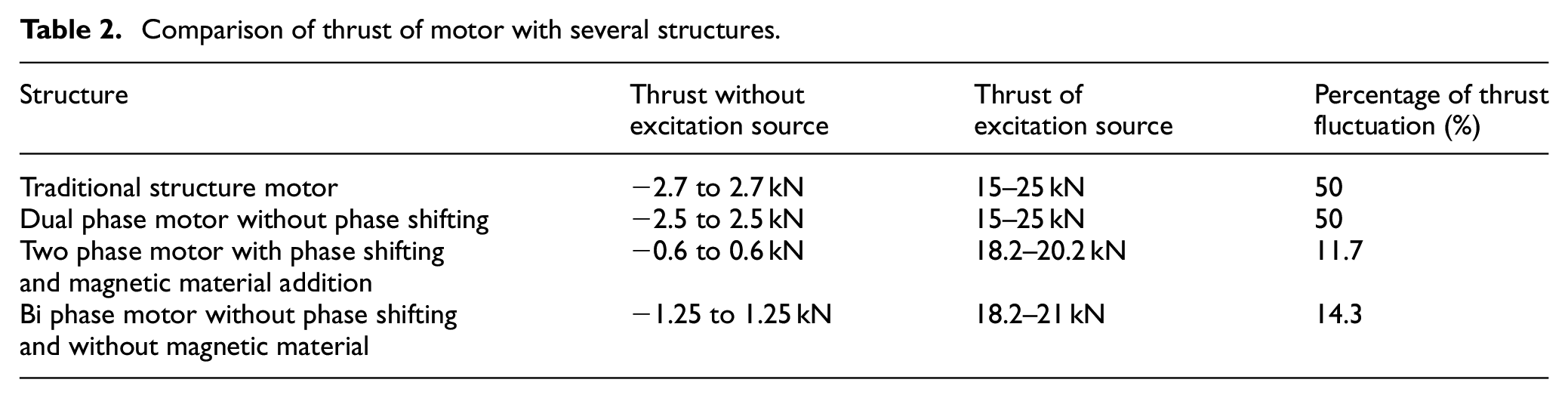
It can be seen from Table 2, the method of using the unit motor in series phase-shifting and displacement simultaneous has an obvious effect on restraining thrust fluctuation of integer slot linear motor, and the unit motor with magnetic isolation material has a better effect of suppressing the thrust fluctuation. That’s because of the addition of magnetic insulation material, the end effect of the two unit-motor also produces a displacement stacking effect, which suppresses the cogging force and also inhibits the thrust fluctuation caused by the end effect.
Comparison of thrust of motor with several structures.
To more effectively illustrate the effect of the elimination of the cogging force by the unit motor proposed in this paper, the main methods for eliminating thrust fluctuation are compared with the methods proposed in this paper, as shown in Table 3.
Comparison of several optimization schemes.

From the simulation results of several models in Table 3, it can be seen that the unit motor series with phase-shifting and displacement simultaneously method of thrust fluctuation of permanent magnet linear motor effect. By using this optimization scheme alone, the thrust fluctuation of the traditional integer slot linear motor is reduced from 50% to about 11%, and the thrust fluctuation of the traditional motor is reduced by about 75%. Also, the optimized integer slot linear motor can also be combined with other optimization solutions to further reduce the thrust fluctuation of the linear motor. Therefore, this method is of great significance for suppressing the thrust fluctuation of the linear motor and improving the stability of the permanent magnet linear motor.
Comparison with stator skew method
Stator skew, meaning that the skew of the stator core on one side deviates from the central axis to produce an Angle, allows the elimination or minimization of cogging torque, which is a common method of eliminating cogging force. The results in Literature González-Palomino et al. 18 show that the stator skew method can reduce the thrust fluctuation of the permanent magnet motor by 54.1%, while the method used in this paper can reduce the thrust fluctuation of the motor by 76.6%, so the method proposed in this paper has a better effect.
Compared with the stator skew method, the proposed method is simpler in structure and technology, has a lower cost, and is more widely applicable.
Conclusion
In this paper, the finite element analysis model of cylindrical permanent magnet linear motor is established and simulated. The linear motor with unit motor structure is analyzed and studied in different situations. The following conclusions are obtained:
1) A new method of phase-shifting and displacement of the unit motor to suppress the thrust fluctuation of the linear motor is proposed. The cylindrical permanent magnet linear motor is split into two-unit motor, and at the same time, a phase-shifting and displacement simultaneously process is performed, and the fluctuation of the thrust of the motor is inhibited. When the unit motor moves half cogging space or so, the suppression of thrust fluctuation is best. This scheme can also be applied to other similar linear motors to reduce the thrust fluctuation of the motor.
2) The magnetic isolation material is used in the middle of the adjacent unit motor, which has the best inhibitory effect on the thrust fluctuation. Without the use of magnetic barrier materials, the suppression of thrust fluctuation is slightly reduced, but the structure and process of the motor are simplified.
3) Divide the traditional linear motor into a unit motor without phase-shifting and displacement. It has the same performance as the original motor and will not suppress the thrust fluctuation of the motor.
4) Compared with the existing methods of suppressing various thrust fluctuations, a new method of linear motor phase-shifting and displacement simultaneously is proposed for the first time in this paper. The method has the best inhibitory effect on thrust fluctuation and is relatively simple in structure and process. Consequently, the method proposed in this paper has strong theoretical significance and practical engineering practical value.
Footnotes
Handling Editor: James Baldwin
Declaration of conflicting interests
The author(s) declared no potential conflicts of interest with respect to the research, authorship, and/or publication of this article.
Funding
The author(s) received no financial support for the research, authorship, and/or publication of this article.