
Abstract
The non-circular planetary gear hydraulic motor is a low-speed and high-torque hydraulic motor with excellent performance. It has the characteristics of a wide speed range, low weight and is widely used in various fields. Aiming to solve the problem of there being no intuitive formula for calculating the displacement of the non-circular planetary gear hydraulic motor at present, based on the analysis of the effects of structural parameters on the displacement of the motor, this paper proposes a formula for calculating the displacement of a non-circular planetary gear hydraulic motor when the pitch curve of the sun wheel is a high-order ellipse. The formula allows the direct calculation and prediction of the displacement of the motor. To improve the unit volume displacement of the hydraulic motor (which determines the power density of the motor), based on the analysis of the unit volume displacement constraints, an optimization equation is proposed by adding an optimization factor to the original equation of the pitch curve of the sun wheel. It is seen that the addition of the new optimization factor eliminates the self-interlacing of the pitch curve of inner ring gear. This elimination increases the unit volume displacement of the motor.
Keywords
Introduction
The hydraulic motor is a hydraulic actuator commonly used in engineering. Specifically, it is widely used for metal cutting machines, 1 load simulators, 2 manipulator arms, 3 vehicles, 4 and motion simulators 5 owing to its characteristics of easy operation and control, a large power-to-weight ratio, reliable operation and large transfer load. Owing to their compact structure and high transmission torque, non-circular planetary gears are widely used in a variety of equipment, such as the wheel stacker and retractor, 6 rice transplanting mechanism, 7 gravity balancing instrument 8 and differential vane pump. 9 The non-circular planetary gear hydraulic motor (also known as a satellite hydraulic motor) is a new type of low-speed and high-torque hydraulic motor, which combines a non-circular planetary gear train and hydraulic motor technology. It has the obvious advantages of a high anti-pollution capacity, a large displacement, a simple structure and low weight.
In 1974, Sieniawski 10 applied the non-circular planetary gear mechanism with a variable center distance to the hydraulic motor and developed the non-circular planetary gear hydraulic motor. Scholars have subsequently further developed and studied this type of hydraulic motor.11,12 In recent years, Sliwinski carried out many studies on the non-circular planetary gear hydraulic motor. He proposed a method of determining the theoretical and actual displacement of the motor by experiment13,14 and studied the effects of water and mineral oil on the motor’s mechanical loss and displacement loss and the leakage of the reversing device.15–17 The reversing device and the axial clearance compensation device of the hydraulic motor have been designed.18,19 In addition, there has been much research on this type of motor. Cao et al. 20 studied the main leakage modes of the motor and established a mathematical model of the clearance leakage. Szkodo et al. 21 found that bending fatigue and surface contact fatigue of the planetary gear train were the main factors of the failure of hydraulic motors. Volkov et al. 22 designed a non-circular planetary gear hydraulic motor with the same number of waves of the solar wheel and the inner gear ring and demonstrated its feasibility.
In research on non-circular gears, Li and Volkov23,24 proposed the method of designing the tooth profile of non-circular gears. Riaza et al. 25 studied the pitch curve of non-circular gears. Xu et al. 26 studied a method of generating the corresponding non-circular gear with a given two-dimensional shape. Volkov et al. 27 compared the quality of different types of planetary gear trains with non-circular gears and concluded that the 2–4, 4–6, and 6–8 types performed best. Furthermore, Volkov et al. 28 completed a comprehensive geometric design of non-circular gear mechanisms. Lin et al. 29 proposed a method based on the envelope principle to obtain an accurate tooth profile of non-circular gears. Mundo 30 proposed a method for the geometric synthesis of an epicyclical gear train able to generate a variable gear ratio law.
Progress has been made in solving the pitch curve of non-circular gears and determining the tooth profile and the kinematic relationship between non-circular gears. The structural design, durability and leakage of non-circular planetary gear hydraulic motors have also been studied. As the core of the hydraulic motor, the non-circular gear directly determines the displacement of the motor. However, at present, there is no clear formula of the relationship between the design parameters of non-circular gears and the displacement of hydraulic motors. The calculation of the existing displacement method (which will be introduced in Section 3.3) is cumbersome, and the quantitative relationship between the design parameters of non-circular gears and the displacement of motors cannot be given. Therefore, the design parameters of the non-circular gear can only be selected by trial and error, which increases the difficulty of hydraulic motor design.
In view of the above problems and on the basis of the study of the relationship between the design parameters of the non-circular gear and the motor displacement, the formula for quantitatively calculating the motor displacement is derived in section 3. This formula plays a guiding role in the selection of non-circular gear parameters and is helpful in understanding the influencing factors of the motor displacement. To improve the power density of the hydraulic motor, the relationship between the design parameters of the non-circular gear and the displacement per unit volume of the motor is further studied. In section 4, a method of optimizing the pitch curve of the non-circular gear such that the optimized hydraulic motor has higher power density is proposed.
Structure and types of non-circular planetary gear hydraulic motors
The structure of the non-circular planetary gear hydraulic motor is shown in Figure 1. The sun wheel is a non-circular gear that is connected to a shaft by a steel ball or spline and rotates with the shaft. The inner ring gear is another non-circular gear, which is connected to the motor housing by a locating pin and remains stationary. The planetary gear is a circular gear that engages with both the solar gear and the inner ring gear. When the sun wheel rotates, the volume of the working volume of the planetary wheel, the sun wheel and the inner gear ring change, and oil absorption and discharge can be realized through the oil distribution device located at the end face of the gear.

Hydraulic motor structure: 1–Inner ring gear, 2–Positioning pin, 3–Planetary gear, 4–Working volume, 5–Sun wheel, 6–Steel ball, and 7–Shaft.
The motor is named after the number of waves of the sun wheel and inner ring gear. In the case that there are four waves of the sun wheel and six waves of the inner ring gear, the hydraulic motor is called a 4–6 type motor. Figure 1 shows a 4–6 type hydraulic motor as considered in this study. The 4–6 type hydraulic motor has a center symmetry, such that the hydraulic radial force of the oil on the shaft is balanced and the motor can thus be used under high pressure.
Formulation of the displacement of the non-circular planetary gear hydraulic motor
This section derives a formula for the displacement of the hydraulic motor. Section 3.1 introduces a method of solving the pitch curve of the non-circular gear and section 3.2 introduces a method of solving the position of the planetary wheel. On the basis of the theory presented in sections 3.1 and 3.2, the method of calculating the displacement introduced in section 3.3 can be used to obtain the corresponding hydraulic motor displacement under different design parameters of the non-circular gears. Using the obtained data, section 3.4 analyzes and summarizes the relationship between the design parameters of the non-circular gears and the motor displacement and finally presents a formula for quantitatively calculating the motor displacement.
Solution of the gear pitch curve
The essence of the design of the non-circular planetary gear hydraulic motor lies in the design of each gear. In the design of a gear, we should first find the solution of the gear pitch curve. In this paper, the pitch curve of the inner gear ring is obtained using the given pitch curve equation of the sun wheel. The known initial conditions are (1) the number of waves of the sun wheel

where
In addition to the high-order elliptic form, the solar pitch curve can be in the form of a high-order Pascal spiral:

Theoretically, the solar pitch curve can be of any form as long as the solar pitch curve is a periodic function with period
The relative positions of the sun gear, planetary gear and inner gear ring in the planetary gear train with non-circular gears is shown in Figure 2. In the figure,

Pitch curve positional relationship of the planetary gear train with non-circular gears.
The equation of the pitch curve of the inner ring gear in polar coordinates is 31

where


In this way, the polar coordinate equations of the curve of the solar wheel pitch and the curve of the inner gear ring pitch are expressed, and both contain unknowns
Closure conditions for the pitch curve of the inner ring gear
The pitch curve of the ring gear pitch must be periodic. The initial conditions have been given above. The number of waves of the inner ring gear is

Conditions for a uniform tooth distribution
The gears on the sun wheel should be evenly distributed, such that 31

The arc length of the inner gear ring is
By solving equations (6) and (7) simultaneously, the unknowns
Solution of the planetary wheel position
There are two typical positions of planetary wheels in motion, as shown in Figures 3 and 4.

Typical position I.

Typical position II.
When

The position of the planetary wheel is deduced as 32


where
Similarly, the position of the planetary wheel when


We assume that the rotation angle of the solar wheel at a certain moment is

By solving equation (14),
Assuming that the planetary wheel at the initial position (
There are
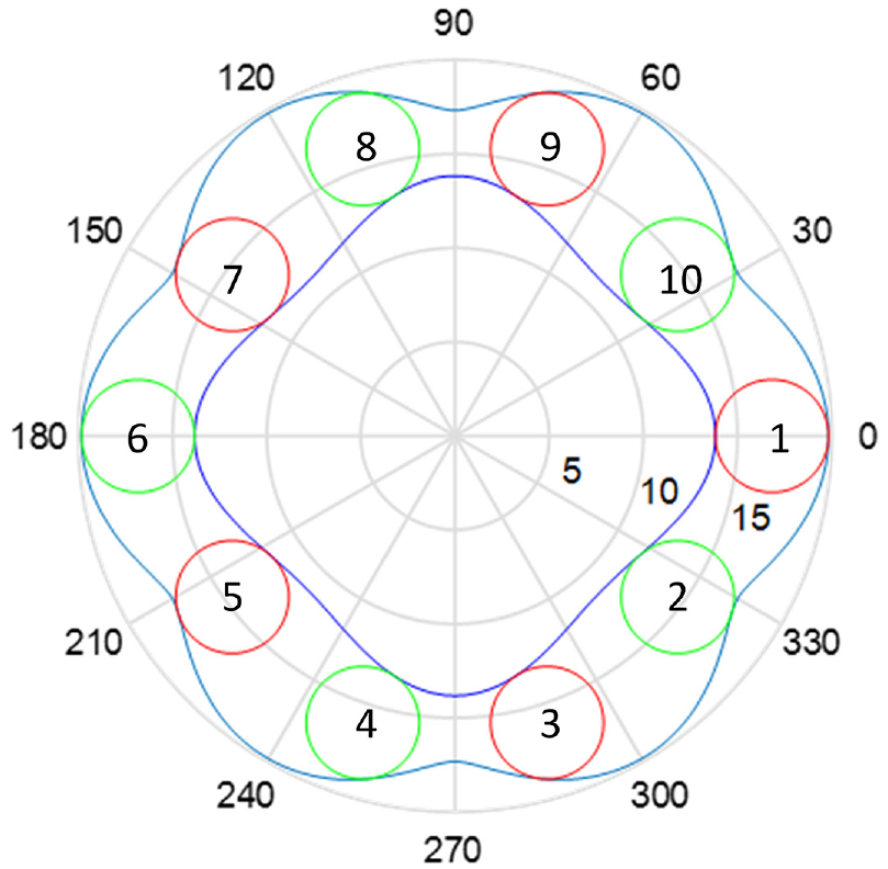
Planetary wheel numbering at the initial position.
Solving the hydraulic motor displacement
To calculate the displacement of the planetary gear train, we should first establish a method of calculating the volume of the enclosed cavity. Figure 6 shows the section of the enclosed cavity enclosed by two planetary wheels. The volume of the enclosed cavity can be obtained by multiplying the area enclosed by the curve abcfeda by the width of the gear

Closed volume section.
The area enclosed by the curve abca is

The area enclosed by curve defd is

The area of the section of the closed cavity is

The volume of the cavity enclosed by neighboring planetary wheels can be calculated for each rotation angle of the sun wheel. There are 10 such cavities for a 4–6 type of non-circular planetary gear train. When the sun wheel continues to rotate, the cavity will absorb/discharge oil if the volume of the cavity increases/decreases. The instantaneous displacement of the planetary gear train can be obtained by summing the volume increase in the oil absorption cavity and then dividing by the increasing angle of the sun wheel. The average displacement and instantaneous displacement pulsation rate of the planetary gear train are thus obtained.
Formulaic processing of the hydraulic motor displacement
The method of calculating the hydraulic motor displacement was given in section 3.3. However, the calculation is complex, and the relationship between the design parameters of the non-circular gear and the displacement of the hydraulic motor cannot be shown directly, which introduces difficulty to the selection of the parameters of the non-circular gear. It is therefore necessary to study in depth the effect of each parameter on the hydraulic motor displacement.
The determination of the pitch curve of the non-circular gear and the thickness
To facilitate the analysis, the gear thickness
Displacement per unit volume
Here, the unit volume displacement

Here,
Selection of teeth
The number of teeth of the planetary wheel
From this point of view, there are many combinations of the number of teeth of the planetary gear and the number of teeth of the sun wheel, which makes it difficult to analyze the effect of the number of teeth on the displacement. It is therefore necessary to find the connection between different types of tooth number combinations. The gear module is certain, and the number of teeth on the gears thus affects the circumference of the pitch curve directly in a proportional relationship. We speculate that when the number of teeth of all gears is expanded
Relationship between the teeth and displacement.

It is seen that the above speculation is correct; that is, when
Therefore, when investigating the effect of the tooth number on displacement, only the less 1 tooth type can be studied, while the other types can be derived from the less 1 tooth type.
Relationship between the tooth number and displacement
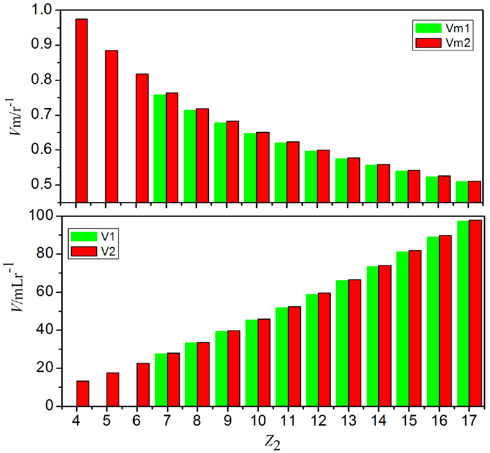
We take the example that the form of the solar pitch curve is a high-order ellipse as equation (1). According to the above description, the displacement and unit volume displacement of the non-circular planetary gear hydraulic motor of the less than 1 tooth type can be obtained, as shown in Table 2.
Relation between the tooth number and displacement.

It is seen that as the number of teeth increases, the displacement increases (inevitably because the size increases) but the displacement per unit volume gradually decreases. In other words, in the less 1 tooth type hydraulic motor, a lower number of planetary gears correspond to a larger displacement per unit volume and better performance.
It is noted that the number of teeth
Derivation of the displacement calculation formula
Taking the high-order ellipse as an example, Table 2 gives 21 sets of data for the number of teeth and displacement of the one-tooth hydraulic motor. The curve fitting method is now used to fit these 21 sets of data. The tooth number


Fitting curve of the displacement versus number of teeth.
When
The formula is extended to other kinds of non-circular planetary gear hydraulic motors that have different values of the planetary gear number, solar gear number, gear thickness and gear module. The gear module and the number of teeth have a linear relationship with the length of the pitch curve, and the displacement thus has a squared relationship with the module whereas the thickness of the gear has a linear relationship with the volume. The general formula of the displacement is thus obtained as

Formula (20) is verified as follows. We first take
It is noted that formula (20) only applies to the high-order ellipses of the solar pitch curve for the hydraulic motor of type 4–6. However, the derivations of the displacement calculation formula for other types of hydraulic motor follow the derivation in this section. Furthermore, the forms of the derived formulas are consistent, with there only being changes in parameters.
Improvement in the hydraulic motor power density
The unit volume displacement
Constraints on unit volume displacement
Table 2 shows that for the hydraulic motor of less 1 tooth type,

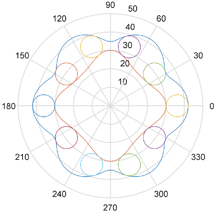
Pitch curves of the solar wheel and inner gear ring: (a)
Figure 8 shows that as
As described in section 3.1, the pitch curve is determined by six initial conditions. Different equation forms of the solar pitch curve can be considered in studying the method of eliminating the self-intersection phenomenon of the pitch curve of the inner gear ring when the number of planetary gear teeth
Optimization equation of the solar pitch curve
There are presently two common equation forms of the solar pitch curve, namely the higher-order ellipse form and the high-order Pascal spiral form, as expressed by equations (1) and (2). However, in theory, as long as the solar pitch curve equation is of a periodic function with period
We know that a periodic function can be expanded as a Fourier series. A periodic function can be expanded as a sine series if the function is odd and as a cosine series if the function is even. The solar wheel needs to ensure consistent performance in forward and reverse rotation, and the solar wheel pitch curve thus needs to be an even function. The solar pitch curve is thus expressed generally as

The high-order Pascal spiral

The effect of coefficient

Pitch curves of the solar wheel and inner gear ring: (a)
Figure 9 shows that a higher coefficient
Comparison of the relationships between the tooth number and displacement before and after optimization.
Figure 10 shows that, in contrast with the commonly used high-order elliptic equation (1), the proposed solar pitch curve equation (22) provides little difference in the unit volume displacement and displacement for the same
Limitation of the selection of the pitch curve by the tooth profile
Section 4.2 judged whether the inner ring gear pitch curve is feasible simply by considering whether the inner ring gear pitch curve is self-interlacing. However, we also need to consider the inner ring gear tooth profile. Some inner gear ring pitch curves are not self-interlacing, but when the pitch curve is too sharp at the minimum radius, there may be an undercut gear. Therefore, when selecting the pitch curve, the tooth profile should be drawn to judge whether the curve is feasible.
We select the less 3 teeth type of hydraulic motor taking

Pitch curves of the sun wheel and inner ring gear for

Tooth profile of the inner ring gear.
Figure 11 shows that when
Example verification
The solar gear pitch curve form is
Pitch curves of the sun wheel, inner gear ring and planetary gear.
The tooth profile is involute when using the profiling method to write a program to draw the tooth profile of each gear. The coefficient of the tooth tip height of the planetary gear is 1, the coefficient of the tooth tip height of the copying rack is 1.2, the pressure angle of the copying rack is
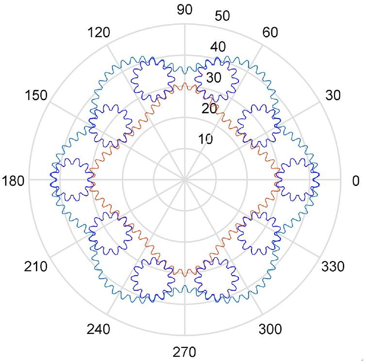
Tooth profiles of the sun wheel, inner ring gear and planetary gear.
Conclusion
This paper investigated the displacement and unit volume displacement of the 4–6 type of non-circular planetary gear hydraulic motor. By establishing equations for the pitch curve of the sun wheel and the inner gear ring in polar coordinates, listing the closing conditions of the pitch curve of the inner gear ring and the condition of a uniform distribution of teeth, and solving the positioning of the planetary wheel, the following innovations were proposed.
The effects of the planetary gear number, solar gear number, gear thickness and gear module on the hydraulic motor displacement were analyzed. On this basis, a formula for calculating the displacement of the non-circular planetary gear hydraulic motor when the solar pitch curve is a high-order ellipse was put forward. The formula for calculating the displacement of the hydraulic motor can be used to calculate and predict the motor displacement easily.
The limiting factors of the unit volume displacement of the non-circular planetary gear hydraulic motor were analyzed, and an optimization equation was put forward by adding an optimization factor to the original equation of the solar pitch curve. It was shown that the newly added optimization factor eliminated the self-intersection phenomenon of the pitch curve of the inner ring gear and increased the unit volume displacement of the non-circular planetary-gear hydraulic motor.
Footnotes
Handling Editor: Maja Čavić
Declaration of conflicting interests
The author(s) declared no potential conflicts of interest with respect to the research, authorship, and/or publication of this article.
Funding
The author(s) disclosed receipt of the following financial support for the research, authorship, and/or publication of this article: The authors would like to give their acknowledgment to the National Key Research and Development Plan (2018YFB2000902) for the financial support to this study.