
Abstract
The forced propagation solution of interfacial shear stress of multilayer cladding structure excited by Love waves is derived by the integral transformation method, and the shear resonance mechanism of interfacial separation is further revealed. The coupling resonance between the excitation frequency and structure intrinsic property causes the peak of interfacial shear stress amplitude, which results in interfacial shear separation at certain frequency bands. It is found that the coupling resonance frequency of interfacial shear stress is only dependent on the inherent properties of the structure, around which the frequency band of interfacial shear separation is formed. The coupling resonance frequency decreases with the increase of the cladding thickness or shear wave velocity difference between the cladding and substrate. The influence of cladding material parameters on interfacial shear stress is greater than that of matrix material parameters. The experimental results support the theoretical analysis results. The conclusions presented could have potential applications in ultrasonic deicing/defrosting/de-sanding and/or coatings protection.
Introduction
In practice, some thin claddings are often accidentally adsorbed and/or burned on the structure surface, such as ice adsorption layers on the surface of wings and rotors, frost deposition layers on heat transfer plate, and sand burning layers on the surface of the casting, and others are actively coated on the structure surface, such as multiple coatings for metal cutting tools.1,2 It has been proved by experiments that both the icing and frosting could be separated from structural surfaces by the mechanical effect of ultrasonic wave.3,4 On the other hand, researchers have been plagued by coating peeling at certain frequency bands of the vibration.5,6 Therefore, interface shear separation mechanism and prediction of cladding structures excited by horizontal shear waves should be studied in depth.
The propagation theory of horizontal shear waves in cladding structures has always been one of the research hotspots of solid mechanics.7–25 The displacement solution of a single cladding structure excited by horizontal shear waves was derived by the integral transformation method, and it was found that the displacement magnitude depends on the excitation magnitude.26–32 The freely propagating solution of horizontal shear waves in the multilayer cladding structure was studied by the global matrix method and the transfer matrix method.33–41 But the derivation of the forced propagation solution excited by horizontal shear waves is complex and difficult, especially in the multilayer cladding structure, which is an exact solution and does not contain any unsolved constants.
In recent years, ultrasonic deicing/defrosting has become one of research hotspots in many industries such as aviation field, air conditioning field and so on. 42 It was proved by finite element methods that the excited interface shear stress result in the interfacial shear strength failure.43–47 In experiments, the ice layer adhered on the metal plate was instantly separated by the ultrasonic transducer.48–52 By finite element methods and experiments, a lot of research on ultrasonic deicing/defrosting has been done.53,54 However, the mechanism of interfacial shear separation of cladding structures excited by horizontal shear waves is still lacking.
In response to the problems raised above, firstly, the full analytical solution of interfacial shear stress of multilayer cladding structures excited by Love waves is exactly deduced. The necessary condition of interface shear separation is analysed and discussed. Secondly, the physical mechanism of interface shear separation is revealed, and the frequency bands are determined. Then, the influence of structural intrinsic properties on interface shear separation is investigated. Finally, by the interface shear separation experiment, the above theoretical results are verified.
The full analytical solution of interfacial shear stress and separation conditions of claddings excited by Love waves
In the multilayer cladding structure shown in Figure 1, λ, μ, ρ and h represent the first Lamé constant, the second Lamé constant, density, thickness. The upper-right corner mark represents the sequence number of the layer. The Love wave propagation direction is the x1 axis direction. The thickness direction is the x2 axis direction. The particle displacement is polarized in the direction of x3.

The multilayer cladding structure.
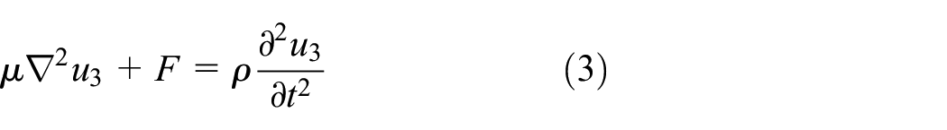
The particle displacement u in an elastic medium satisfies the following Navier equation,

According to the plane strain hypothesis, for horizontal shear waves in semi-infinite structures, u1 = u2 = 0,

Substituting the above displacement components into (1), it can be simplified as
The plane Love wave excitation source is applied to the multilayer cladding in the x1 = 0 plane, which could be expressed by the Diracray function as,

Here, f0 is the excitation amplitude,


Here, f is the excitation frequency.
The displacement components in the claddings and substrate respectively satisfy the following wave equations (For convenience, the time-harmonic factor e−iωt is not considered in the following derivation),

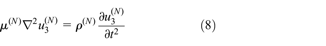
Here,

Due to the introduction of external force F, (7) cannot be solved by conventional methods, such as the method of separation of variables.
The relationship between the shear stress and displacement component is

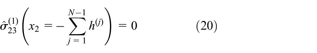
It is the boundary condition that the surface is traction-free, the displacement and the stress are continuous across interfaces and the displacement is zero when the x2 approaches infinity. The above boundary condition could be expressed as


As partial differential equations (7)–(8) could not be solved directly, which could be eliminated to ordinary differential equations by the following integral transformation formula,


Taking the Fourier integral transformation of (7)–(8), (10) and (11)–(14) on x1, we obtain


Here,


Here, s is the integrating factor.
We take


Therefore, the general solutions of the ordinary differential equations (17) and (18) are assumed to be
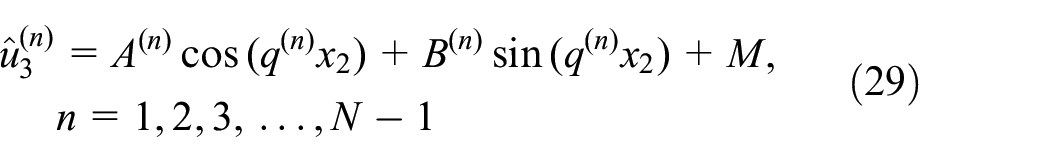

Here, A (n) , A (N) , B (n) and B (N) are the unsolved constants,

Substituting the general solution (29)–(30) into the boundary conditions (20)–(23) by (19), we obtain an inhomogeneous system including 2N equations with respect to A(n), A(N), B(n) and B(N). Then, by solving the system,
Here, the conditions (27) and (28) that the integrating factor s must satisfy simultaneously could be simplified as


It can be inferred from (32) and (33) that the necessary condition for the existence of s is

Here,

The interval where s exists could be written as


By (25) and (34), the necessary condition for the existence of s could be written as

Here,

From (35), in the multilayer cladding structure, Love wave exists when the maximum shear wave velocity of all cladding layers is less than that of matrix. The condition could also be specialized to the case of only one cladding, in which Love wave exists when the shear wave velocity of the cladding is less than that of matrix. This is the same as the description of the classical Love wave in the relevant literature, which also verifies the correctness of this method.
Finally, taking the inverse Fourier integral transformation of (29)–(30) on x1, we obtain the full analytical solution of the displacement component of multilayer cladding structure excited by Love waves.

The upper and lower limits of the integral (40) must satisfy the existence condition (36)–(37) of the integrating factor s.
Then, through the relationship (10) between displacement and stress, the full analytical solution of the shear stress of multilayer cladding structure excited by Love waves is obtained.

Finally, by substituting the coordinates of the interface in (41), the full analytical solution of the interface shear stress of multilayer cladding structure excited by Love waves is obtained.
For the interface shear strength loaded by the symmetrical cyclic alternating stress, combined with the fatigue strength failure theory, the necessary condition of shear delamination of the lower interface of the n-th cladding is

Here, the left end of (42) is the maximum value of interface shear stress of the lower interface of the n-th cladding,

Here,
The maximum value of symmetrical cyclic alternating stress is equal to its amplitude.

Therefore, the necessary conditions of shear delamination of the lower interface of the n-th cladding could also be expressed as
If it is assumed that

where, C (n) is the ratio of [σ−1] (n) to f0,
Then, we obtain
Equation (47) is the necessary condition of shear separation of the lower interface of the n-th cladding excited by Love waves. Its left end is the normalized interface shear stress amplitude. Its right end is the ratio of the allowable stress of the interface shear fatigue strength to excitation amplitude.
It could be known from (47) that the interfacial shear separation is not only related to the normalized interface shear stress amplitude but also to the ratio of the allowable stress of the interface shear fatigue strength to excitation amplitude. When the ratio of the allowable stress of the interface shear fatigue strength to excitation amplitude is known, the normalized interface shear stress amplitude is a key factor in interfacial shear separation analysis of claddings.
In engineering practice, the single cladding as a special case of multilayer claddings is encountered the most, as shown in Figure 2. It is of more practical significance to study the interfacial shear delamination of the single cladding. The expression of interface shear stress

The single cladding structure.
Therefore, from (47), the necessary condition of interfacial shear separation of the single cladding structure excited by Love waves is

Then the frequency band of interfacial shear separation of the single cladding structure excited by Love waves could be determined by (48).
Mechanism and prediction for interfacial shear separation of cladding excited by Love waves
The plaster layer attached to a semi-infinite aluminium substrate is taken as an example. Firstly, the coupling resonance characteristic of the interface shear stress amplitude is discussed, and taking C(1) = 2.5, the frequency bands of interfacial shear separation are determined by (48). Then, the influence of the structure inherent property on the coupling resonance frequency and excitation frequency bands of interfacial shear separation is investigated. Finally, the influence of the structure inherent property on the interface shear stress and parameter intervals of interfacial shear separation at usual power ultrasonic frequencies is studied.
Coupling resonance characteristics and frequency bands of interfacial shear separation
Analytical results of interface shear stress amplitude are calculated by adaptive Gauss-Kronrod quadrature numerical integration methods, which are verified by the finite element solution, as shown in Figure 3. In addition, the Love wave dispersion curve is also drawn to compare. The plaster layer thickness is 3.5 mm and other material parameters are shown in Table 1. The excitation frequency band of interfacial shear separation of plaster layer is also calculated.

Analysis and finite element results of normalized interface shear stress amplitude, excitation frequency bands (the shaded portion) of interfacial shear separation of the plaster layer and dispersion curves.
Material parameters.

As shown in Figure 3, within 0–450 kHz, the normalized interface shear stress amplitude has three resonances and two anti-resonances. The resonance and the anti-resonance appear alternately. The resonance peak gradually decreases while the anti-resonance valley gradually increases with the increase of excitation frequency. When the excitation frequency tends to infinity, the normalized interface shear stress amplitude tends to a fixed value which is independent of the excitation frequency. Combining the dispersion curve, it is found that the coupling resonance of the normalized interface shear stress amplitude occurs at the minima of group velocities of each order mode. The excitation frequency band (the shaded portion) of interfacial shear separation of the plaster layer is formed around the coupling resonance frequency, which narrows as the number of modes increases. Analytical results of the interface shear stress amplitude agree well with finite element results with a maximum error of 3%, which may be caused by calculation methods.
Analysing Figure 3, we are convinced that the interface shear stress amplitude is closely related to the group velocity. We are sure that the coupling resonance effect between the wave and the structure is the strongest when the propagation speed of wave energy is the lowest at the minima of group velocities of each order mode, which results in the coupling resonance of the interface shear stress amplitude. The coupling resonance frequency depends only on the inherent properties of the structure, which is optimal for interfacial shear separation.
The influence of the structure inherent property on the coupling resonance frequency and frequency bands of interfacial shear separation
By the orthogonal experiment method, taking material parameters shown in Table 1 and 7.5 mm plaster layer thickness as a reference group, the influence of structure inherent properties on the coupling resonance frequency and excitation frequency bands of interfacial shear separation is investigated.
As shown in Figure 4, the distribution of the coupling resonance frequency in the excitation frequency and structure intrinsic property domains is calculated.

Distributions of the coupling resonance frequency in the excitation frequency and cladding thickness domains (a), the excitation frequency and cladding density domains (b), the excitation frequency and matrix density domains (c), the excitation frequency and cladding shear modulus domains (d), the excitation frequency and matrix shear modulus domains (e), the excitation frequency and cladding shear wave velocity domains (f), and the excitation frequency and matrix shear wave velocity domains (g).
As shown in Figure 4, the coupling resonance frequency has a negative correlation with the cladding thickness, the cladding density and the substrate shear wave velocity, while has a positive correlation with the cladding shear modulus and the cladding shear wave velocity. The resonance peak of interface shear stress amplitude has a negative correlation with the cladding shear modulus, the cladding shear wave velocity and the substrate density, while has a positive correlation with the cladding density, the substrate shear modulus and the substrate shear wave velocity.
Analysis of Figure 4 shows that coupling resonance frequencies decrease when the cladding thickness or the shear wave velocity difference between the cladding and the substrate increases, and the corresponding resonance peak of interface shear stress amplitude increases when the shear wave velocity difference between cladding and substrate increases.
As shown in Figure 5, excitation frequency bands of interfacial shear separation in the structure intrinsic property domain are calculated.

Excitation frequency bands (shaded portions) of interfacial shear separation in the cladding thickness domain (a), the cladding density domain (b), the matrix density domain (c), the cladding shear modulus domain (d), the matrix shear modulus domain (e), the cladding shear wave velocity domain (f) and the matrix shear wave velocity domain (g).
As shown in Figure 5, excitation frequency bands move to the low frequency region as the cladding thickness or cladding density increase, which is made up of several shaded parts. Excitation frequency bands move to the high frequency region as the matrix density, cladding shear modulus or cladding shear wave velocity increase. Excitation frequency bands are almost constant when the matrix shear modulus or shear wave velocity of the matrix increase.
The influence of the structure inherent property on the interface shear stress and parameter intervals of interfacial shear separation at 50, 150 and 250 kHz
By the orthogonal experiment method, taking material parameters shown in Table 1 and 7.5 mm plaster layer thickness as a reference group, the influence of structure inherent properties on the interface shear stress and parameter intervals of interfacial shear separation at the usual power ultrasonic frequency of 50, 150 and 250 kHz is investigated.
The influence of the structure inherent property on the interface shear stress and parameter intervals of interfacial shear separation at 50 kHz
As shown in Figure 6, the distribution of the interface shear stress in the substrate and cladding intrinsic property domains is calculated at 50 kHz.

Distributions of the interface shear stress at 50 kHz in the cladding density and matrix density domains (a), the cladding shear modulus and matrix shear modulus domains (b) and the cladding shear wave velocity and matrix shear wave velocity domains (c).
As shown in Figure 6, the influence of cladding material parameters on the interface shear stress is obviously greater than that of matrix material parameters.
As shown in Figure 7, parameter intervals of interfacial shear separation in the substrate and cladding intrinsic property domains at 50 kHz are determined.

Parameter intervals (shaded portions) of interfacial shear separation at 50 kHz in the cladding density and matrix density domains (a), the cladding shear modulus and matrix shear modulus domains (b) and the cladding shear wave velocity and matrix shear wave velocity domains (c).
As shown in Figure 7, parameter intervals made up of several shaded parts appear intermittently when the cladding density, cladding shear modulus or cladding shear wave velocity increase, which are almost constant when the matrix density or matrix shear modulus increase, and widen slightly as the matrix shear wave velocity increases. Therefore, the influence of cladding material parameters on parameter intervals is obviously greater than that of matrix material parameters.
The influence of the structure inherent property on the interface shear stress and parameter intervals of interfacial shear separation at 150 kHz
As shown in Figure 8, the distribution of the interface shear stress in the substrate and cladding intrinsic property domains is calculated at 150 kHz.
Distributions of the interface shear stress at 150 kHz in the cladding density and matrix density domains (a), the cladding shear modulus and matrix shear modulus domains (b) and the cladding shear wave velocity and matrix shear wave velocity domains (c).
As shown in Figure 8, the influence of cladding material parameters on the interface shear stress is obviously greater than that of matrix material parameters.
As shown in Figure 9, parameter intervals of interfacial shear separation in the substrate and cladding intrinsic property domains at 150 kHz are determined.
Parameter intervals (shaded portions) of interfacial shear separation at 150 kHz in the cladding density and matrix density domains (a), the cladding shear modulus and matrix shear modulus domains (b) and the cladding shear wave velocity and matrix shear wave velocity domains (c).
As shown in Figure 9, parameter intervals made up of several shaded parts appear intermittently when the cladding density, cladding shear modulus or cladding shear wave velocity increase, which are almost constant as the matrix shear modulus increases, narrow slightly as the matrix density increases, and widen slightly as the matrix shear wave velocity increases. Therefore, the influence of cladding material parameters on parameter intervals is obviously greater than that of matrix material parameters.
The influence of the structure inherent property on the interface shear stress and parameter intervals of interfacial shear separation at 250 kHz
As shown in Figure 10, the distribution of the interface shear stress in the substrate and cladding intrinsic property domains is calculated at 250 kHz.

Distributions of the interface shear stress at 250 kHz in the cladding density and matrix density domains (a), the cladding shear modulus and matrix shear modulus domains (b) and the cladding shear wave velocity and matrix shear wave velocity domains (c).
As shown in Figure 10, the influence of cladding material parameters on the interface shear stress is obviously greater than that of matrix material parameters.
As shown in Figure 11, parameter intervals of interfacial shear separation in the substrate and cladding intrinsic property domains at 250 kHz are determined.

Parameter intervals (shaded portions) of interfacial shear separation at 250 kHz in the cladding density and matrix density domains (a), the cladding shear modulus and matrix shear modulus domains (b) and the cladding shear wave velocity and matrix shear wave velocity domains (c).
As shown in Figure 11, parameter intervals made up of several shaded parts appear intermittently when the cladding density, cladding shear modulus or cladding shear wave velocity increase, which are almost constant as the matrix shear modulus increases, narrow slightly as the matrix density increases, and widen slightly as the matrix shear wave velocity increases. Therefore, the influence of cladding material parameters on parameter intervals is obviously greater than that of matrix material parameters.
Analysing Figures 6 to 11, we are convinced that the cladding material parameter has a greater impact on the interface shear stress and parameter intervals of interfacial shear separation than the base material parameter at the usual power ultrasonic frequency.
Interfacial shear separation experiments of claddings by Love waves
Taking a sandwich-type ultrasonic transducer as the excitation source, plaster layers adhered to an aluminium substrate are shear-separated at the interface by gradually increasing the output power.
Experimental materials and methods
The ultrasonic transducer with resonant frequency 40 ± 0.5 kHz, rated power 100 W, static capacitance 6700 ± 10% pF, resonance impedance ≤20 Ω, insulation impedance (2500VDC) ≥100 MΩ, dimensions 55 × 47 mm (diameter × height) is driven by an ultrasonic generator, which could automatically search for the optimal resonance frequency of the system around 40 ± 2 kHz and has output power of eight levels consisting of 12.5, 25, 37.5, 50, 62.5, 75, 87.5 and 100 W. An aluminium block of 800 mm × 100 mm × 55 mm is used as the substrate, which is supported at both ends by plastic foams. The average size of the plaster layer is measured by a vernier caliper.
Shear waves excited by the axial vibrating ultrasonic transducer propagate symmetrically from the centre of the matrix to both ends, which form Love waves at thin plaster claddings. Its polarization direction is vertical along the sticking surface, as shown in Figure 12. The plastic foams are used to absorb the reflected waves at both ends of the substrate to eliminate the effects of standing waves.

Snapshots of: (a) the experiment start, (b) 3.0 mm thick plaster layer shear separation, (c) 1.7 mm thick plaster layer shear separation and (d) the experiment end.
Experimental results
As shown in Figure 12, because the shear wave velocity of gypsum is much smaller than that of aluminium, and the thickness of gypsum layer is much smaller than the size of aluminium block in the same direction, when a part of shear waves excited by the ultrasonic transducer propagate from the matrix to the plaster layers, Love waves in the plaster layers are formed.
As shown in Figure 12, the left plaster layer thickness is 1.7 mm, and the right plaster layer thickness is 3.0 mm, and the optimal resonance frequency of the system is 39 kHz. When the actual output power of the ultrasonic transducer was gradually increased from 12.5 to 62.5 W, plaster layers remained unchanged. However, once the actual output power reached 75 W, the 3.0 mm thick plaster layer was first shear-separated. Then, the 1.7 mm thick plaster layer was also shear-separated as the actual output power reached 100 W step by step, which was broken into two pieces by the tabletop. Especially it is noticed that there were some tiny and crisp cracking sounds when plaster layers were shear-separated, but plaster layers remained intact before landing.
Analysis and discussion
Analysing Figure 12, we are convinced that the interfacial shear stress amplitude excited by the ultrasonic transducer is responsible for the plaster layer shear separation, which is greater than the allowable stress of the interface shear fatigue strength when the plaster layer is shear-separated. When the interface was layering, the tiny and crisp fracture sound was emitted, which had nothing to do with the interfacial tensile and compressive stress because plaster layers were not broken before landing. Above all, it is proven that the larger the plaster layer thickness, the larger the interface shear stress amplitude excited by the ultrasonic transducer.
Finally, the correlation between the critical output power of interfacial shear separation and the plaster layer thickness is counted by experiments, see Figure 13.

Experimental and theoretical results of interfacial shear separation of the Love wave.
From (46), we obtain

Substituting (49) into (48), the necessary condition of interfacial shear separation of the single cladding structure is obtained.

According to (50), the critical condition for interface shear separation is as follows.

The left side of (51) is the critical excitation amplitude normalized to the allowable stress of the interface shear fatigue strength, and the right side is the reciprocal of the normalized interface shear stress amplitude. The theoretical correlation between the critical excitation amplitude and the plaster layer thickness is obtained by (51).
In the plaster layer thickness domain, the critical output power of experimental results is compared with the critical excitation amplitude of theoretical results, as shown in Figure 13.
As shown in Figure 13, both experimental statistics results and theoretical analysis results show that there is a negative correlation between the plaster layer thickness and the critical output power as well as the critical excitation amplitude of interfacial shear separation. The trend of experimental results is the same as that of theoretical analysis.
Conclusions
The coupling resonance mechanism of interfacial shear separation of multilayer cladding structures excited by Love waves is investigated. The full analytical solution of interface shear stress and the condition for interface shear separation are derived. The influence of the structure inherent property on the coupling resonance frequency and frequency bands of interfacial shear separation is investigated. The influence of material parameters of cladding and matrix on the interface shear stress and parameter intervals of interfacial shear separation at the usual power ultrasonic frequency is compared. The correlation between the plaster layer thickness and the critical output power of interfacial shear separation is studied by experiments. Here are the main conclusions of this article.
The interfacial shear stress amplitude is related to both the excitation source and the structure inherent property. The excitation source amplitude is only the coefficient of the interface shear stress amplitude. The necessary condition of interfacial shear separation is that the interfacial shear stress amplitude is greater than the allowable stress of the interface shear fatigue strength.
The interface shear stress amplitude has the coupling resonance characteristic at the minima of group velocities of each order mode, which of the resonance peak becomes smaller and smaller and eventually reach a constant value which is independent of the excitation frequency. The coupling resonance frequency is an inherent property of the structure. The frequency band of interface shear separation is formed around the coupling resonance frequency, which is getting narrower and narrower.
With the increase of the cladding thickness or the shear wave velocity difference between the cladding and substrate, the coupling resonance frequency decrease and the frequency band of interfacial shear separation moves towards the lower frequency region.
The influence of the cladding material parameter on the interfacial shear stress and parameter intervals of interfacial shear separation is greater than that of the base material parameter.
The experimental results show that there is a negative correlation between the cladding thickness and the critical output power of interface shear separation and the reason of interface shear separation is that the interface shear stress amplitude excited by the ultrasonic transducer is greater than the interface shear fatigue strength. Under the same excitation, the greater is the cladding thickness, the greater is the excited interface shear stress amplitude.
The result could be applied not only to the interface shear separation of claddings, but also to the interface protection, for example, multilayer coated metal cutting tools actively avoiding the harmful frequency band of coatings shear separation. The frequency interval left after removing the frequency band of interface shear separation is the interface protection frequency interval. In addition, the result is applicable only where surfaces are flat. The case where the surface is curved will be studied in the future.
Footnotes
Appendix A
The following excitation source is loaded on the cladding in the x1 = 0 plane.
Here,
Here, f is the excitation frequency.
For Love waves, the displacement u of particles in the cladding and the matrix satisfies the following wave equation respectively (For convenience, the harmonic factor is ignored in the following derivation).
Here,
The shear stress formula is as follows.
The boundary conditions are expressed as follows,
The following integral formula is used.
Here, s is the integrating factor.
Taking the Fourier integral transformation of (A.4)–(A.5), (A.8) and (A.9)–(A.12) on x1, we obtain
Here,
If we take
Then the general solution of (A.15) and (A.16) is assumed as follows.
Here, A(1), A(2), B(1) and B(2) are unsolved constants,
Substituting the general solution (A.26) and (A.27) into (A.18)-(A.21) by (A.17), we obtain
Here,
From (A.24)-(A.25), s must satisfy the following conditions.
Therefore, the necessary conditions for the existence of s are as follows,
From (A.22), it could also be expressed as
(A.37) is also the existence condition of Love wave in classical literature.
If s exists, it’s going to be in the range
Performing the inverse Fourier integral transform of (A.26) and (A.27), the full analytical solution of displacement component of the single cladding structure excited by Love waves is obtained.
The upper and lower limits of the integral of equation (A.39) must satisfy the existence condition (A.38) of the integrating factor s.
Using the formula (A.8), the full analytical solution of shear stress of the single cladding structure excited by Love waves is obtained.
At the interface x2 = 0, the full analytical solution of interface shear stress of the single cladding structure excited by Love waves is obtained.
Handling Editor: James Baldwin
Declaration of conflicting interests
The author(s) declared no potential conflicts of interest with respect to the research, authorship, and/or publication of this article.
Funding
The author(s) disclosed receipt of the following financial support for the research, authorship, and/or publication of this article: This work was supported by the National Natural Science Foundation of China (Grant No. 51675401).