
Abstract
In this paper, the Layer-wise theory was improve based on the alternate characteristics of layer angle of composite hollow shaft. The ±φi laminate was considered as the minimum mechanical analysis element, which can effectively simplify the stress coupling in mechanical analytical method. On this foundation, a 3-D analytical method of bending stiffness <EI> for thick-walled composite hollow shaft was derived. The CFRP hollow shaft specimens made of same dimensions but different laminate were used for bending test. Then, the bending stiffness calculated by theory of beams, 2-D analytical method, 3-D analytical model and experiment were compared. All the results show that the 3-D analytical model predicts the bending stiffness of thick-walled composite hollow shaft more precisely than the theory of beams and analytical method, and agree well with experimental results. And the 3-D analytical model can reflect the influence of stacking sequence on the bending stiffness of the composite hollow shaft.
Introduction
As Carbon Fiber Reinforced Plastic (CFRP) has the advantages of high specific strength, high specific modulus, large damping ratio and fatigue resistance, hollow shaft made of CFRP is especially suitable for transmission systems with long span, large torque, and high rotation speed.1,2
It is well-known that the critical bending speed of the CFRP transmission shaft is related to the bending stiffness of the CFRP hollow shaft.3,4 Badie et al. 5 studied the natural frequency of a drive shaft with 6.35 mm radius and 1.48 mm wall thickness. The drive shaft was idealized as a thin shell tube and simply supported beam, and found that critical bending speed of the CFRP transmission shaft can be increased by increasing the axial modulus. Moorthy et al. 6 designed an automobile drive shaft with 54.28 mm radius and 5.72 mm wall thickness using carbon/epoxy composite, and investigated the bending natural frequency. Abu Talib et al. 7 developed a FEA model to analyze a composite transmission shaft, and studied the effects of orientation angle and stacking sequence on the critical bending speed. Babamohammadi et al. 8 represent an analysis on the mechanical characterization of fiber reinforced hollow circular based on a 3D shell model, which only considered the in-plane strain. Khalkhali et al. 9 optimized a composite automotive drive shaft by considering the fundamental natural frequency and critical buckling torque. All the accessed studies3–9 on natural frequency treated the composite driveshaft as thin-walled cylinders. Important parameter (bending stiffness) of the transmission shaft was simply predicted by classical thin lamination theory or calculated by FEA using the thin shell element, and regardless of whether the composite hollow shaft satisfied thin wall condition (radius/wall thickness ≥ 10). In fact, most composite transmission shaft in their papers cannot be defined as thin-wall tube because the radius was not 10 times larger than the wall thickness, which will cause calculation deviation.
Many studies have researched the bending stiffness of layered thick-walled composite tube used as structure beams. Yazdani Sarvestani et al. 10 proposed a high-order displacement-based method to investigate stresses and strains in thick arbitrary laminated orthotropic cantilever straight tubes under transverse loading, and verified by comparing the theoretical results with experimental data, finite-element method (FEM), and Lekhnitskii solution. Yazdani Sarvestani and Hojjati 11 used a new high-order simple-input analytical method to simulate ground handling, thick laminated composite straight tubes subjected to pure bending moments. And a simple non-dimensional coefficient was also proposed to predict interlaminar radial stresses of thick composite straight tubes. Menshykova and Guz 12 and Sun et al. 13 performed the bending stiffness analysis of layered thick-walled composite pipes subjected to bending loading. Sarvestani et al. 14 proposed a new simple-input displacement based on layer-wise formulation method for the stiffness analysis of thick laminated composite straight tubes subjected to cantilever loading.
Most design studies about bending stiffness were not including the wall thickness consideration, which may need to be explored in relation to composite shafts design. And the researches about structure beams had analyzed the thick-walled composite hollow, but those methods have limited applicability and were not effective for multi-angle laminate. Thus, 3-D analytical model based on the improved Layer-wise theory is proposed in this paper, which can calculate the bending stiffness of thick-walled composite hollow shaft quickly and accurately.
3-D bending stiffness analytical model
Modified layer-wise theory
In this part, the layer-wise theory was modified by considering the forming process of the composite hollow shaft (filament-wound or rolling process). The laminate of this composite shaft has the feature that the φ and −φ layers are adjacent and equal thickness. According to this, the 3-D-strain relationship of each ±φ layer element were deduced. The cylindrical coordinates system, namely (z, θ, r) is used to describe the multi-layered filament-wound hollow shaft (shown in Figure 1).

Multi-layered filament-wound tube in coordinate systems.
The constitutive equations in cylindrical coordinates for the generally orthotropic layer at a fiber angle φ are determined by a transformation of stiffness matrix [Q] through the angle φ. 15

Considering the forming process of the composite hollow shaft, the φ and -φ layers are adjacent and equal thickness. The composite hollow can be discreted into mechanics analysis elements (shown in Figure 2), each element contains two adjacent layers with orientation angel φ and -φ.

Discrete method of modified Layer-wise theory.
It can be visualized that

In the general beam theory, the beam behaves as a thin-walled shell, which not includes out-of-plane stress components σr, σθ, and τθr. However, when the beam belongs to a thick-walled structure, the contribution of the out-of-plane stresses components may become important and must be considered in the analytical solution. 16 The coupling relationship between the in-plane and out-of-plane strains can be expressed as 17 :

where

Substituting equation (3) into equation (2), the cross section stress-strain relationship for the kth±φ layer in the thick-walled hollow is expressed as:

and

Based on the relationship of

The modified Layer-wise theory considers the off-cross-sectional stress components, and also can effectively eliminate the coupling of normal stress and shear stress. Which can simplify the mechanical analytical method.
Equivalent bending stiffness
In this part, the balance equation of bending deformation of hollow shaft is used to obtain the relationship between strain and bending moment. And then, by combining with the modified Layer-wise theory, the equivalent bending stiffness was built. The relationship between the bending moment and axial stress of the composite hollow shaft should be as follows 18 :
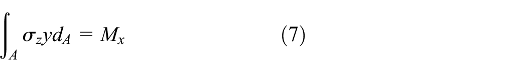
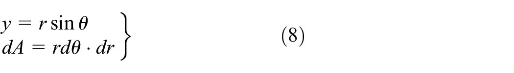
where Mx is bending moment. A is the area of cross-section of the composite hollow and y is the distance from minim cell dA to the axis (shown in Figure 3), which can be expressed as following equations in the cylindrical coordinate.

The axial strain of kth±φ layer under bending load: (a) the cross-section of kth±φ layer and (b) the axial deformation of dA.
Substituting the axial layer stress (4) and equation (8) into the relation (7),

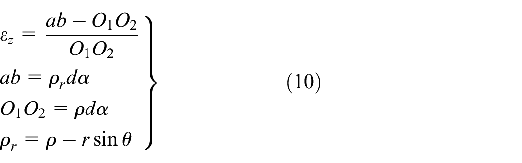
From classical bending theory of beams, the neutral surface is the x–z plane when subject to bending moment Mx. The intersection of the neutral surface and cross section is the neutral axis (arc O1O2 in Figure 3), and the initial length of minim cell dA in axis direction equal to arc O1O2. Thus the axial strain of minim cell can be calculated by:
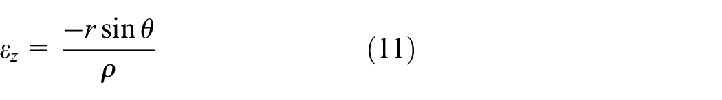
And the axial strain can be expressed as:
By combining axial strain equation (11) and bending moment equilibrium equation (7). The equation (9) can be written as:

The bending moment equilibrium equation can be written as 19 :

where
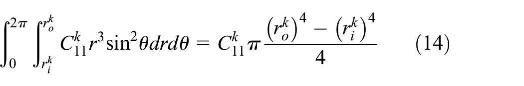
Substituting the integral (14) into (13):

And the equivalent bending stiffness <EI> of the thick-walled composite hollow is:

Experimental work
The three-point bending,14,20,21 four-point bending, 11 pure bending 22 and cantilever stiffness test 23 methods are usually used to study bending behavior of composite hollow. In three-point and four-point bending tests, the specimens have high concentrated transverse loads at the supporting and loading points, which will cause compression damage before bending failure occurred, but the test method and equipment is easy and simple. Compared to three-point and four-point test, the pure bending test do not have this problem. 24 For this paper only research the bending stiffness of the composite hollow shaft, the three-point bending test is chosen to measure the bending stiffness before compression damage occurred at the loading point.
The bending test was carried out to verify the accuracy of the 3-D analytical model. The fiber orientation angle adopts five typical angles (±5°, 90°, and ±45°). For easy comparison, the inner and outer diameters of specimens were the same, while the layer scheme were varies. The CFRP hollow shaft specimens were manufactured by warm rolling process by using T700/YPH-308 prepreg (from ZHONGFU SHENYING CARBON FIBER CO., LTD.), the properties are shown in Table 1. The preprege is made up of T700 carbon fiber and YPH-308 epoxy with 68% and 32% volume fraction respectively. The curing cycle is divided into two steps, the first step last 30 min with 90°C temperature and 0.3 MPa pressure, then the temperature rises to 140°C and pressure to 0.6 MPa and last long 60 min. Table 2 shows the details of the composite hollow shaft specimens.
Material properties of CFRP T700/YPH-308.

Configuration and dimensions of specimens.

Mechanical testing machine was used to perform the three-point bending test (shown in Figure 4). The applied load and maximum deflection of the hollows were measured by displacement sensor in the load head. The span is 250 mm, and the bending force was applied in the middle of the specimen by the speed of 5N/s, and the sampling frequency of the sensors was 10Hz. The experimental temperature was 25°C and humidity was 45%, which met the ASTM D7264 (Standard test method for flexural properties of polymer matrix composite materials).

Three-point bending test with a specimen mounted on it.
Results and discussion
The results of bending test, theory of beams, 12 2-D analytical model 11 and 3-D analytical model were compared as follows:
In the load-deflection linear segment of the tests, no damage occurred at the loading and supporting position, and the specimens are in the flexural elastic domain. The load dropped when the compression damage began to occur at the loading position. In the three-point bending test, the fibers above the neutral plane are under compressive stress (as shown at dA in Figure 3), and the fibers below the neutral plane are under tensile stress. The axial compressive stress generated by the bending at the loading position is the largest, and this position also suffers a radial compressive stress due to the extrusion of the loading head. The axial and radial compressive stress lead to the initial matrix compression damage, fiber fracture damage and delamination damage in the composite layers where the loading position located(as shown in Figure 5). These initial damages cause stiffness degradation of the CFRP tube, leading to a sudden decrease of the slope of the Force-Bending deflection curve. In this case, the damage is not caused by bending compression, but by the crushing of the specimen surface by the load head. But it will not affect the bending stiffness calculation.

The morphology fracture at the loading position.
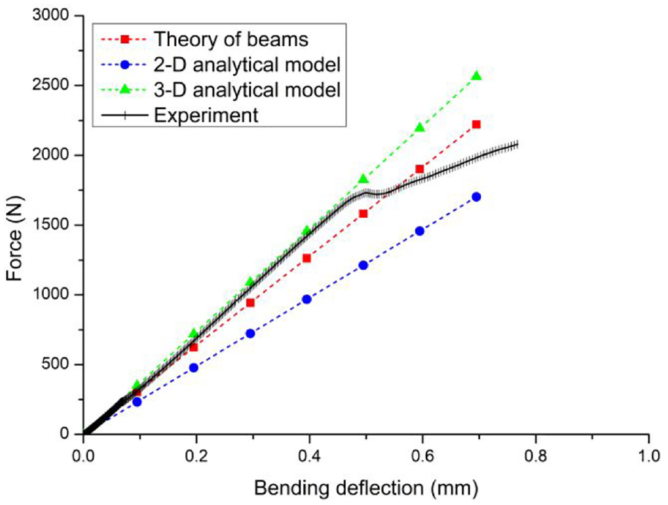
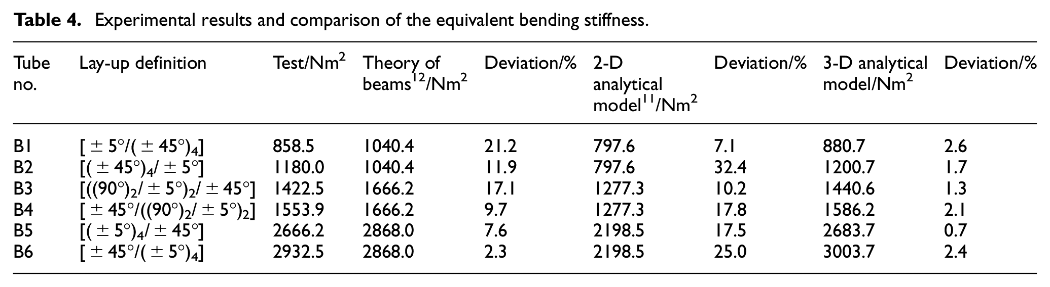
From Figures 6 to 11, the slopes of applied load versus bending deflection in the linear segment of the experimental results can be obtained from linear fitting (shown in Table 3). Experimental results (shown in Table 4) for equivalent bending stiffness can be calculated based on the slopes and specimens’ size. All the results show that the bending stiffness increased when the percentage of ±5° layer in the laminate increased, which indicated that increasing the percentage of the small angle fiber orientation can effectively increase the bending stiffness of the composite hollow shaft. By comparing the results of 3-D analytical model with experiment, it can be seen that the equivalent bending stiffness calculated by 3-D analytical model agree well with the experimental results (the maximum deviation is 2.6%). From the results of specimens with the same fiber orientation angle and the percentage (group B1 and B2, or group B3 and B4, or group B5 and B6), the bending stiffness of laminate with small fiber orientation angle layers located on the outside of the wall thickness is larger than the ones with the small fiber orientation angle layers located on the inside. This is consistent with the experimental results. The theory of beams and 2-D analytical model predicted the same bending stiffness of the hollow with the same fiber orientation and percentage, and has large error with the experimental results (maximum deviation is 21.2% and 32.4%, respectively). This is due to the lack consideration of the coupling effects of the in-plane and out-of-plane strains in the composite hollow shaft.

Force-Bending deflection curve of specimen B1.
Force-Bending deflection curve of specimen B2.

Force-Bending deflection curve of specimen B3.

Force-Bending deflection curve of specimen B4.

Force-Bending deflection curve of specimen B5.
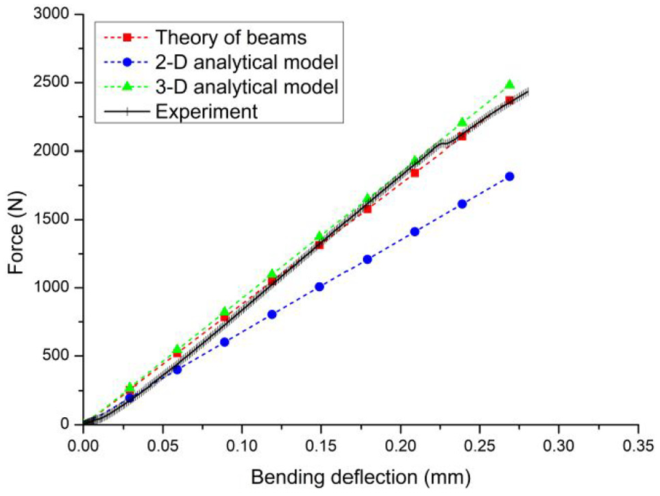
Force-Bending deflection curve of specimen B6.
The slopes of the linear segment of the experimental results.

Experimental results and comparison of the equivalent bending stiffness.
Conclusions
In this study, the Layer-wise theory was improve based on the alternate characteristics of layer angle. Based on this, a 3-D analytical model of bending stiffness for thick-walled composite hollow shaft was derived. Which consider the out-of-plane stress components, and can effectively eliminate the coupling of normal stress and shear stress. For validation purposes, six composite hollow shafts have been manufactured and tested. The bending stiffness calculated by theory of beams, 2-D analytical method and 3-D analytical model were compared, and the following conclusion can be drawn as follows:
The stacking sequence effects the bending stiffness of the composite hollow shaft, and the layers with small fiber orientation angle located on the outside of the hollow can increase the bending stiffness.
The 3-D analytical model predicts the bending stiffness of thick-walled composite hollow shaft more precisely than the theory of beams and 2-D analytical method, and agree well with experimental results.
Footnotes
Handling Editor: James Baldwin
Declaration of conflicting interests
The author(s) declared no potential conflicts of interest with respect to the research, authorship, and/or publication of this article.
Funding
The author(s) disclosed receipt of the following financial support for the research, authorship, and/or publication of this article: This research was supported by the Ph.D. Research Fund of Hubei University of Arts and Science (No. 2059065), the Fund of Hubei Superior and Distinctive Discipline Group of Mechatronics and Automobiles (No. XKQ2020008), and the Hubei Provincial Natural Science Foundation (No. 2018CFB313).