
Abstract
Aging populations in developing countries have driven increased research interest in issues related to “eldercare,” with a particular focus on early fall detection. This article describes an approach to processing images captured using a depth camera to predict the probable inclination of an imminent fall by a pedestrian. First, the 3-D object reconstruction method is explained and realized. Then, the 3-D object inclination analysis is given. Experimental results show prediction rates achieved accuracy up to 98.11%, making this approach promising for use in applications in hospital and home environments in the near future.
Keywords
Introduction
Fall detection technologies can be divided into two categories, 1,2 wearable sensors 3 –10 and image-based mechanisms. 11 –13 The increasing power and ubiquity of smart phones and the emergence of other wearable devices have broadly increased the application of wearable-type sensors in fall detection. Tang et al. 9 used a motion capture system to capture the 3-D coordinates of a reflective marker so as to calculate the angular displacement and velocity of the ankle to effectively detect leg sprain and falls caused by the sudden rotation of the ankle joint. However, wearable devices may not provide an ideal solution for elderly users or medical patients, because such users may forget to wear them, protect them from water, or keep them charged. Hospitals and elder care facilities thus primarily rely on image-based fall detection systems, and the present research only considers this type of approach.
Image-based fall detection technologies are divided into three categories based on their specific hardware characteristics.
2-D images: Images are taken from a single camera to determine falls.
10
–15
Wang et al.
14
performed tracing and limb motion analysis by performing feature marking on the user. Liao et al.
15
applied a Bayesian belief network model to pedestrian characteristics to detect slips and falls. 3-D images: Two or more cameras are used to capture 3-D images for fall detection in an ideal hardware configuration.
16,17
Depth images: Depth information for each pixel in a 2-D image is used to produce a 3-D image. Structured light cameras are used to obtain image depth, including Microsoft’s Kinect and time-of-flight cameras.
2-D image-based fall detection is generally less accurate than 3-D detection. In addition, 2-D approaches require the use of markers 14 or are restricted by the need to learn pedestrian characteristics. 15 3-D images provide more complete information, but depend on the use of time-consuming algorithms. Image depth techniques are frequently used as a compromise.
The Kinect depth camera uses a built-in human skeletal analysis algorithm or 3-D bounding box to detect falls. 18 –21 However, the algorithm is imperfect and can produce incorrect results, such as when the target figure is lying prone. 22,23
All fall detection techniques must determine the subject’s inclination relative to the vertical. In 2-D image-based techniques, 13,15 curve fitting is used to create an ellipse which approximates the subject’s outline. The angle between the ellipse’s major axis and the vertical is then calculated as the subject’s inclination.
Current methods do not adequately detect subject inclination, which is the key to detecting falls. 24,25 Rougier et al. 13 and Liao et al. 15 use a 2-D image which cannot produce the actual inclination of a 3-D object. To address this issue, the present article proposes a method to obtain the inclination of a 3-D object.
Yang and Lin 1 proposed a fall determination flow using a depth camera. Although the fall determination technique is powerful, the subject’s inclination may be incorrect in some cases.
In the work of Yang and Lin, 1 the subject’s centroid is selected as the new origin. A line passing through the origin is found to minimize the sum of the distance between the line and the edges of the subject’s outline.
Earlier works 1 , 13,15 all rely on 2-D images and are thus cannot calculate the subject’s correct inclination when the fall direction is parallel to the camera.
Obtaining the subject’s correct inclination entails first reconstructing the 3-D object and then calculating its inclination. The minimization of the sum of the 3-D distance is actually an orthogonal regression or total least squares problem. 26
Lay 27 mentioned that principal component analysis (PCA) is equivalent to orthogonal regression methods, thus this article utilized PCA to derive the inclination of the 3-D object which is the result of orthogonal regression (i.e. the sum of the squares of the orthogonal distances to the spatial line is minimized).
This article focuses on 3-D object reconstruction and object inclination calculation (see “Fall detection system assessment” and “Experimental results” sections). The fall determination flow is implemented through six processes: foreground extraction, overlapping segmentation, object reconstruction and detection, object tracking, calculating (object inclination calculation Δθt ), and fall event determining (Figure 1).
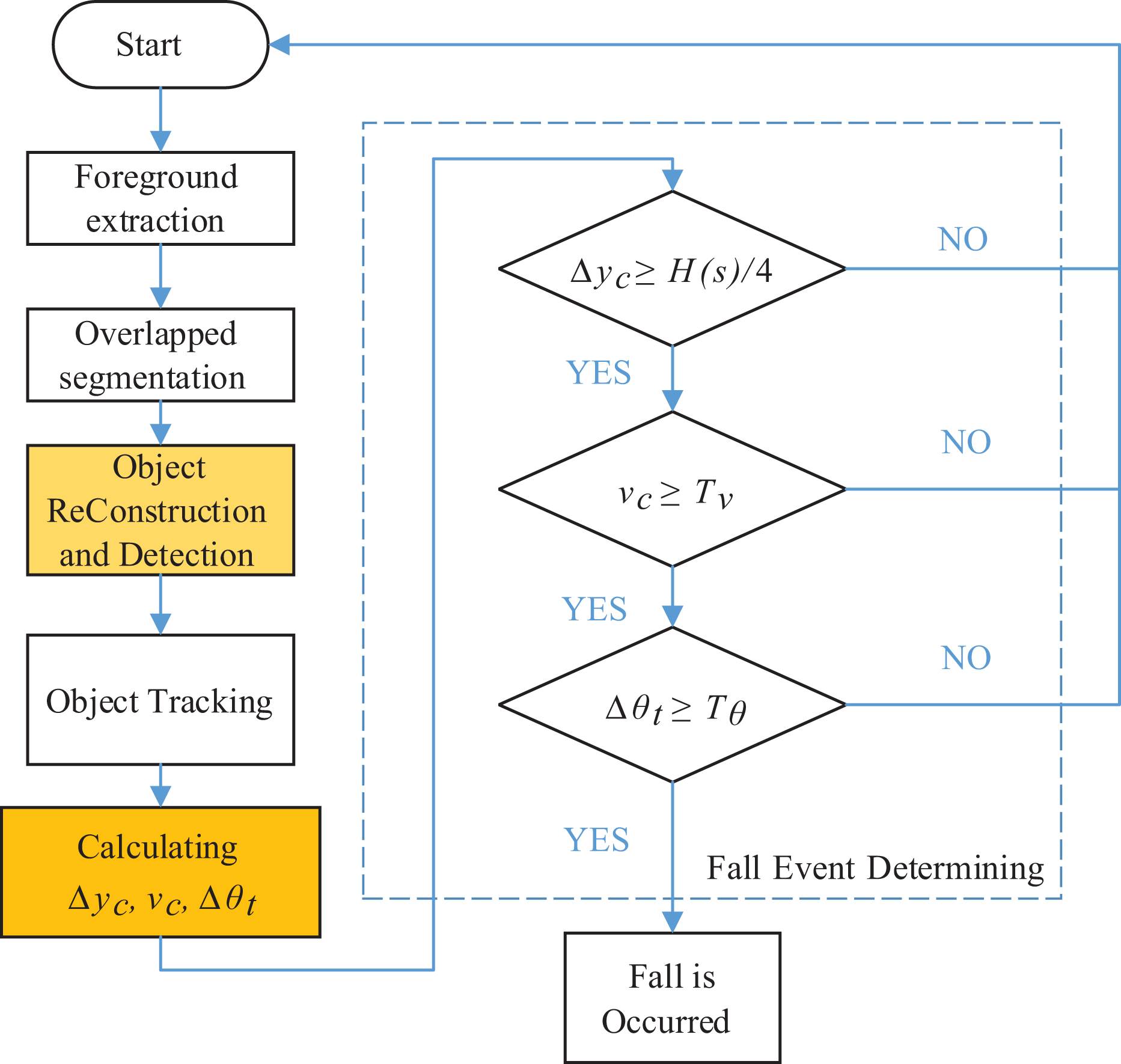
Fall determination flow. 1
This article proposes a new method to calculate 3-D inclination using information extracted from a Kinect unit. PCA is then used to calculate the 3-D inclination of a human subject. The proposed method significantly improves on fall detection accuracy when the subject falls in a direction which is parallel to the camera, with detection accuracy approaching 100%.
Methods
3-D object reconstruction
In addition to providing depth information in millimeter units, the Kinect depth camera also creates 2-D images measured in pixels. Yang and Lin 1 propose transforming a depth image into a point cloud based on the 3-D coordinates of the depth camera and transforming the 2-D image into real measurements in millimeter. It is also necessary to convert the camera’s coordinates into earth coordinates to completely reconstruct the 3-D object and thus obtain a more accurate angle of the object’s inclination.
Correctly tracking these objects requires separating this overlap and then calculating the fall characteristics. These tasks use coordinate information which must be calculated using a geodetic coordinate system. The camera’s coordinate information must be converted from the projection coordinate system to a real-world coordinate system, and then to an earth coordinate system.
The method described in the previous section operates at a right angle earth coordinate system. Therefore, this section explores how the information obtained from the depth camera is then converted to a spatial position in a geodetic coordinate system.
The depth camera’s image plane is a projection coordinate system (see Figure 2), using pixels as units. Assume that the resolution of the image plane is w × h pixel
2
, and the plane size is

Relationship between the camera’s projection coordinate system and the real-world coordinate system.
If a given pixel’s coordinate value is


Then, assume the camera’s horizontal and vertical fields of view are, respectively, θw and θh , and the camera’s focal length is f mm. The following relationships can be derived from Figure 3

Triangular relationship between the projected coordinate system and the real-world coordinate system.
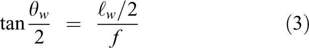
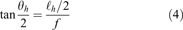


These two equations use only four constants: w, h, θw , and θh .
The camera is installed on the wall near the ceiling with different real-world and earth coordinate systems. To calculate the angle of inclination, the real-world coordinate system must be rotated to coincide with the earth coordinate system.
The relationship between the two right-angled coordinate systems can be expressed as Euler angles: The z-axis is rotated ϕ, after which the new coordinate system y-axis is rotated θ. Finally, the new coordinate system z-axis is rotated ϕ. This result is the product of three rotation matrices: Rot(z, ϕ), Rot(y, θ), and Rot(z, ϕ). Because we only aim to calculate the inclination against the vertical from the ground to the sky (i.e. against gravity) as the earth coordinate system’s y-axis and do not consider the x-axis, only the plane XZ must be horizontal. Therefore, only two rotations are required to align the real-world and earth coordinate systems: rotate the z-axis ϕ such that the x-axis falls on the horizontal plane, and rotate the x-axis θ, such that the y-axis is a plumb line.
The geodetic coordinate system is defined as EG
= {
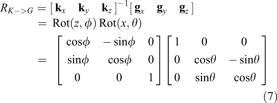
If the space in the camera’s real-world coordinate system is (xk , yk , zk ), and the earth coordinate system is expressed by (xg , yg , zg ), then

can obtain
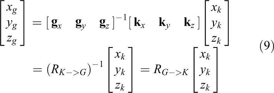
Since RK->G is an orthogonal matrix, (RK->G )−1 = (RK->G ) T .
The angles ϕ and θ are difficult to measure and must be obtained using system identification. The camera orientation identification method is used to record the depth camera image using a vertical line perpendicular to the ground and a horizontal line parallel to the ground to obtain the camera’s position in the real-world coordinate system. The laser light is directly projected onto the screen to obtain information needed for experimental setup.
First, using the real-world coordinate system, we select all vertical laser lines, with a total of n pixels above the vertical laser line. These points are referred to as

Vertical and horizontal laser reference point.
Then, the laser projected on the screen to create a point cloud map. Intuitively, the laser beam should be straight, but the point cloud shows jitter due to the depth camera resolution, as shown in Figure 5.
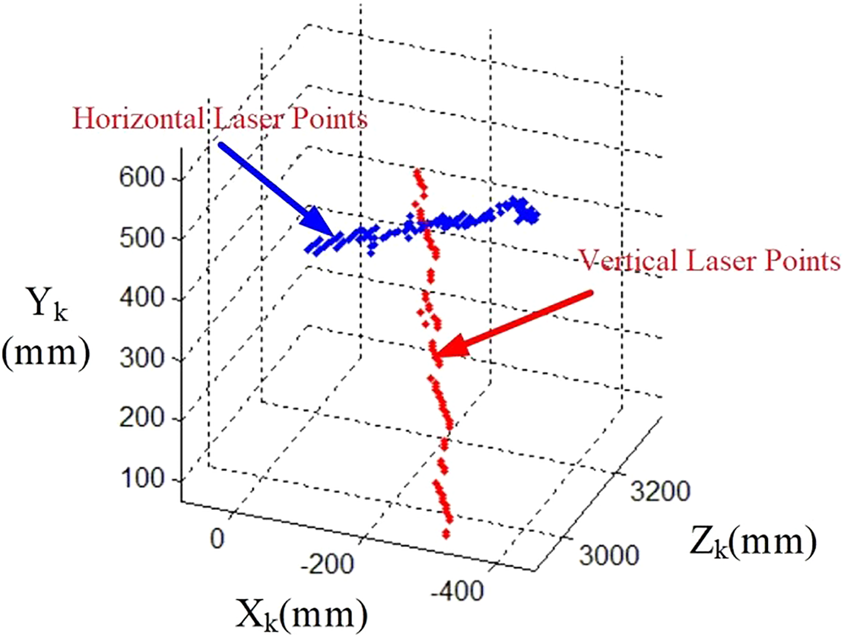
Laser point cloud map.
If we directly take any two point vectors within the laser point cloud diagram, the selection of different locations may result in deviation between the calculated linear vector and the actual laser line. To solve this problem, this article analyzes the principal components of vertical and horizontal lines and obtains the main vector to represent the two laser lines. The approximate line obtained from PCA calculations of the laser points as shown in Figure 6.
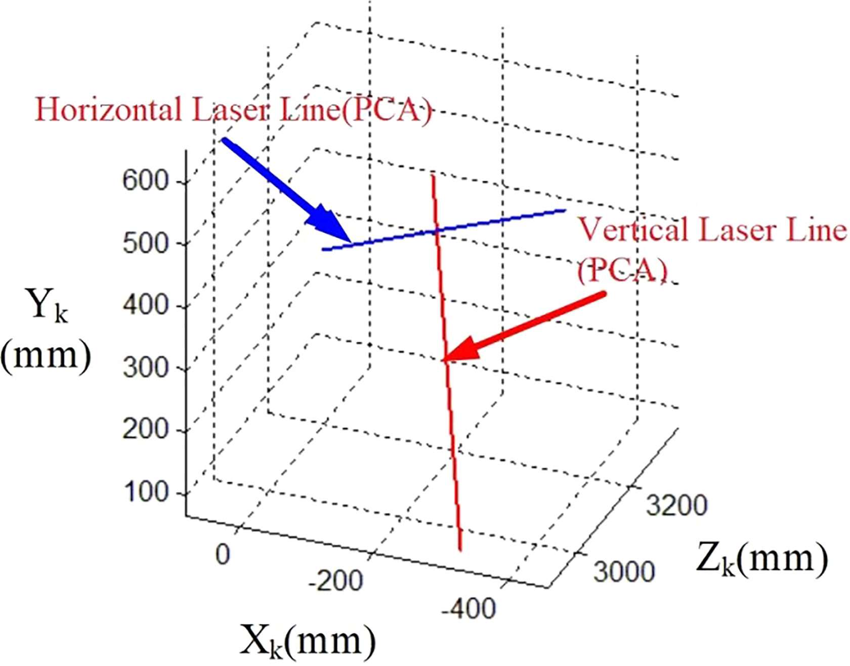
Approximate line obtained from PCA. PCA: principal component analysis.
PCA operation is applied to all points of the vertical laser line to obtain the first principal component

By reducing the second column from the first, we obtain

Similarly, using the horizontal laser line, we can obtain θ as follows

where
The earth coordinate system transition results are shown in Figure 7.

Earth coordinate system laser line.
As seen in Figure 7, the proposed 3-D object reconstruction method can reconstruct the intersection of the two laser beams, where the vertical line and the XgZg plane (earth) is the vertical and the horizontal line and the XgZg plane is the horizontal.
3-D object inclination calculation
This article uses a 3-D object inclination calculation method to monitor changes between the inclination of a pedestrian and the vertical as a basis for detecting falls.
Inclination calculation
Figure 8 shows a point cloud for a 3-D object. Assume a total of n pixels for


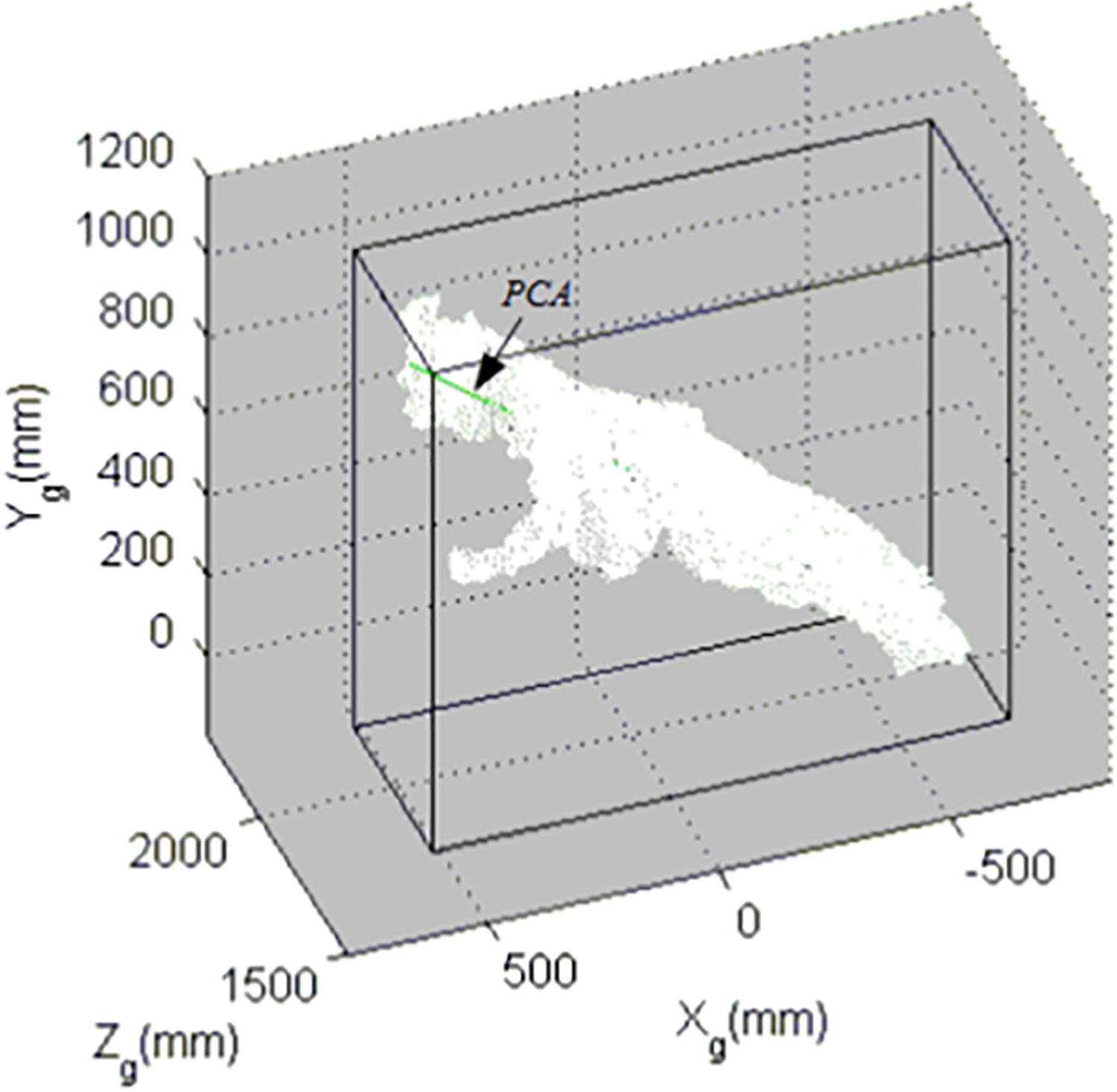
Point cloud pixels for a 3-D object.
This n point vector

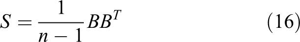
Clearly, S is a symmetric matrix, so an orthogonal matrix Q can be found to diagonalize it. This orthogonal matrix Q is composed of the eigenvectors

The diagonal elements of the matrix D are arranged in descending order. The largest eigenvalue λ
1 corresponds to the eigenvector
Orthogonal conversion does not change vector lengths. That is
Inclination verification
In this subsection, we verify the PCA calculation results in “3-D object reconstruction” section, where the subject is standing, squatting, sitting down, bending over, or falling in the direction parallel to the camera view and validate results for when the direction of the fall is not parallel to the camera view.
Figure 9 shows the PCA calculation for the 3-D inclination of a subject, with PCA used to obtain the subject’s axis through PCA.

PCA 3-D inclination verification original image and result: (a) standing, (b) squatting, (c) sitting down, (d) bending over, (e) falling parallel to the camera view, and (f) falling nonparallel to the camera view. PCA: principal component analysis.
These six different types of validation show that, regardless of posture, PCA can be used to correctly determine the subject’s axis. Thus, compared to the work of Yang and Lin,1 the proposed approach offers a more accurate calculation of the subject’s actual inclination, thus increasing detection accuracy.
Experimental results and discussion
Fall detection system assessment
To assess system performance in accurately determining falls, experiments were conducted with falling and non-falling subjects to determine system results in terms of true positive (TP), false positive (FP), false negative (FN), and true negative (TN; see Table 1).
Behavioral states.
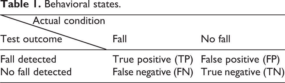
TP indicates that a fall event was correctly recognized, FP indicates that a fall event was recognized despite no fall having occurred, FN indicates that a fall occurred but was not detected, and TN indicates that the system correctly found no fall had occurred.
From the above data, we can define system accuracy, precision, sensitivity, and F-score. Accuracy is defined as the ratio of correct detection results to all detection results as follows

Precision is defined as the ratio of falls to correct fall detection as follows

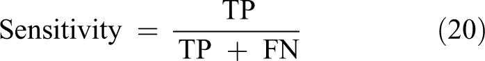
Sensitivity is defined as the ratio of correctly detected falls to actual falls as follows
F-score is defined as the harmonic mean of precision and sensitivity as follows

F-score is used to illustrate the ideal degree of experimental methods, with a higher harmonic mean indicating a more ideal method.
Experimental results
Identical experiments were performed in three contexts: an empty classroom, a laboratory, and a corridor. In the tests, subjects walked back and forth three times, sat three times, or stooped to pick up an object on the floor three times. During the tests, subjects either fell or did not. Falling tests were conducted with falling in a direction either parallel or nonparallel to the camera view, each repeated six times.
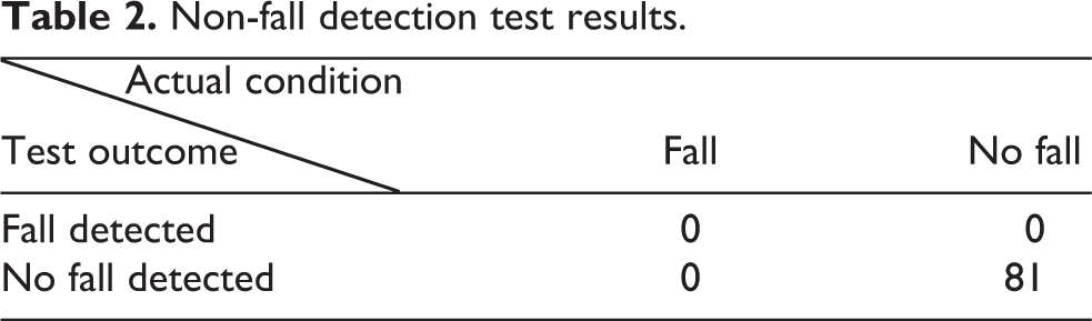
Figure 10 shows non-fall behavior detection results in different contexts: walking, sitting, and picking up objects, with the green frame in each image indicting non-fall behavior detected. The three subjects completed a total of 81 non-fall actions, with detection results presented in Table 2, and analysis results presented in Table 3. Table 2 presents that FP is zero, indicating that the system did not generate any FP outcomes, with an accuracy of 100%.

Detection of non-fall behavior: (a) walking, (b) sitting down, and (c) stooping to pick up objects.
Non-fall detection test results.
Non-fall detection result analysis.

Figures 11 and 12, respectively, show fall and non-fall behavior parallel and nonparallel to the camera view. In the figures, the red frame shows fall behavior detected by the system. Three subjects engaged in 108 instances of fall behavior. Test results are given in Table 4 and are analyzed in Table 5.

Detection of falls walking parallel to the camera: (a) prior to fall and (b) after fall.

Detection of falls walking perpendicular to the camera: (a) prior to fall and (b) after fall.
Fall detection test results.

Fall detection result analysis.

Table 4 presents an FN count of 4, indicating that the system missed several falls, but these instances all occurred when the fall action was blocked from the camera’s view by another subject. Under such conditions, the system treats both subjects as a single object, resulting in failure to correctly acquire the object features. The proposed method has a precision of 100%, sensitivity of 96.30%, and an F-score of 98.11%, while the results in the work of Yang and Lin1 provide a precision of 94.31%, sensitivity of 85.57%, and F-score of 89.73%.
Discussion
Based on these experimental results, the proposed 3-D inclination calculation approach improves on the fall detection mechanism proposed in the work of Yang and Lin,1 raising the sensitivity from 85.57% to 96.30%, thus reducing the incidence of FN detection results, especially when the subject falls in a direction parallel to the camera.
This article presents a fall detection system using a depth camera. The proposed solution differs from others using 2-D images in that the depth camera provides depth information for each pixel, allowing us to determine the object’s position in 3-D space, thus allowing for object tracking and fall detection.
Conclusion
The proposed method first reconstructs the 3-D object to correct for errors when the subject falls parallel to the camera, and then uses a PCA approach to calculate the 3-D inclination as a key feature for determining falls. The proposed system detects non-fall behavior with 100% precision, while fall behavior is detected with 100% precision, 96.30% sensitivity, and an F-score of 98.11%. The system uses a depth camera device, making it inexpensive and easy to use, and thus suitable for use in hospital and home environments for hospital patients and those with reduced mobility, thus increasing the safety of living environments while reducing the cost of nursing care.
Footnotes
Declaration of conflicting interests
The author(s) declared no potential conflicts of interest with respect to the research, authorship, and/or publication of this article.
Funding
The author(s) disclosed receipt of the following financial support for the research, authorship and/or publication of this article: This research was supported by the Ministry of Science and Technology Grant ID (MOST 105-2221-E-106).