
Abstract
A robust controller is developed for the trajectory tracking control of a 6-DOF robotic crusher in task space. Firstly, the dynamic model including the mantle assembly and actuators is derived by Lagrange method according to the virtual work principle. In order to simulate the crushing behavior of cone crusher in the crushing chamber, the trajectory model of the mantle assembly is achieved by ADAMS. Then, a robust controller which contains the dynamic compensation is designed, and the convergence stability of the 6-DOF robotic crusher is strictly proved based on Lyapunov stability theory. Finally, the co-simulation is used to verify that the proposed controller can solve the problem of model uncertainties and external disturbances well. Meanwhile, numerical simulation results of the 6-DOF robotic crusher illustrate the proposed controller is able to effectively reduce the trajectory tracking errors compared with the computed torque controller.
Introduction
Compression crushers are common in the metallurgy, chemical, and aggregate industries, such as gyratory, cone, and jaw crushers.1–3 Gyratory crusher and jaw crusher are used for primary crushing while cone crusher is applied in secondary and tertiary crushing. 4 The main performance parameters of crushers include particle size, shape, and output. After years of development, researchers have studied the cavity shape, wear, operation model, and power consumption of the crushers.5–7 Multi-objective models were established based on the crushing chamber, yield, and size reduction, which take into account the rotational speed, eccentricity, and base angle. 8 A geometric model for predicting the wear of cone crusher was developed considering the influence of shear force along the crushing surface. 9 According to the energy consumption model of cone crusher, the effect of working conditions and structural parameters was studied. Numerical results show that speed, eccentric angle, and closed side setting (CSS) are important factors affecting energy consumption. 10 These make the performance of the crushers greatly improved, but also bring great economic value. However, crushers have low flexibility due to the limitations of their own mechanisms. Take cone crusher as an example, the eccentric angle and discharge port of each crusher are fixed, and the crushing behavior is relatively simple. Meanwhile, parallel robots are widely used in aviation, shipping, and entertainment facilities because of their high rigidity, large payload, and high flexibility.11–13 A 6-DOF robotic crusher is developed by combining the crushing chamber of cone crusher with the intelligence of parallel robot. 14
Trajectory tracking control is a difficult issue for the 6-DOF robotic crusher due to its complex kinematic and dynamic modeling. In the early works, computed torque controller is one of the traditional dynamic controllers, which contains the PD control term and the dynamic compensation term. Meanwhile, other different tracking control strategies are proposed, such as PID controller, sliding mode controller, and adaptive controller.15–17 A PID controller with feedback linearization was developed to track the trajectory of a6-DOF parallel robot. 18 Back-stepping sliding mode controller was used to control the position of pneumatic actuator based on the dynamic model. 11 An adaptive backstepping sliding mode controller is designed based on the six degrees of freedom model of airship, where the backstepping technique is used to obtain the desired velocities, and the adaptive sliding mode method is adopted to deal with the unknown model uncertainties. 19 An adaptive controller for 6-DOF driving simulator was proposed according to the linearized dynamic equation model, which was used for position tracking. The internal and external control loops were adopted, and the PD controller, adaptive compensation method were combined to design the controller. 20 Adaptive control can be designed to restrain the uncertainty of model parameters by timely identification, learning, and adjusting the control law. However, the limitation is that the tracking performance is not satisfactory in the presence of external disturbances. As a kind of robust control, H∞ control adopts feedback linearization method to process the mathematical model, and then designs the feedback controller according to the linear H∞ control theory. However, the disadvantage is that the limit of model uncertainties should be determined in advance, and it is easy to ignore the unmodelled dynamic characteristics in the process of linearization, which will reduce the robustness of the system. As the 6-DOF robotic crusher is a newly proposed crushing machine, the control strategy for it has not been reported at present. But we can confirm that the system is characterized by the model uncertainties and external disturbances. The motivation of this study is to design a control scheme to solve the mentioned problems.
Motivated by the above discussions, a robust controller is developed to guarantee the convergence of tracking errors for the 6-DOF robotic crusher subject to the model uncertainties and external disturbances. The proposed method uses feedback linearization theory to completely compensate the nonlinear terms of the 6-DOF robotic crusher, which can generate a globally linearized and decoupled closed-loop equation. Then the mature linear control theory is applied to the system design, so that the system can achieve satisfactory performance requirements. The contributions of this study are presented as follows. Firstly, according to the virtual work principle, the dynamic model of the6-DOF robotic crusher is established by using Lagrange method. Secondly, a robust controller combined with dynamic compensation is proposed, and the convergence stability of the system is strictly proved based on Lyapunov stability theory. Specifically, the disturbance suppression ability is analyzed. Finally, simulation results are compared with the developed computed torque control (CTC), which show that the proposed robust control can achieve better trajectory tracking accuracy for the 6-DOF robotic crusher.
The rest parts of this paper are organized as follows. In Section 2, after introducing the 6-DOF robotic crusher, the control objective is formulated. In Section 3, trajectory planning scheme, robust controller design, and the closed-loop stability analysis are given. In Section 4, numerical results and simulation discussion are presented. Finally, conclusions are given and the future work is indicated in Section 5.
Problem statement
Structure of a 6-DOF robotic crusher
A 6-DOF robotic crusher is composed of a crusher drive unit (CDU) and a crusher fixed unit (CFU), 21 which can be shown in Figure 1. CDU consists of six actuators and a mantle assembly, which mainly provides power for crushing the material. CFU is connected to the ground and plays a fixed role. The connection mode of the actuators, mantle assembly, and foundation are spherical hinge. The mantle assembly can realize many kinds of motion in the crushing chamber by changing the lengths of the actuators.
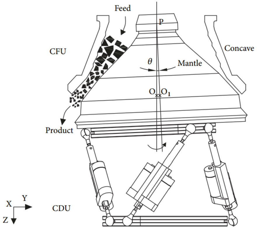
Operating principle of a 6-DOF robotic crusher.
The crushing process of the material in the crushing chamber can be represented by several crushing zones. The material is squeezed and crushed in the whole crushing zones, and the two adjacent crushing zones are continuous. Then, the final product can be excluded from the open side setting (OSS). The 6-DOF robotic crusher has strong flexibility, which can evolve into many types of crusher, such as gyratory crusher, cone crusher.
Dynamic model
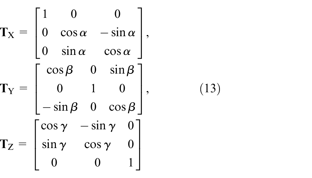
As shown in Figure 2, a mantle assembly frame {O1, X1,Y1,Z1} and a reference frame {O, X, Y, Z} are established. The dynamic model of the 6-DOF robotic crusher can be derived from Lagrange equation, which is expressed as22,23:

where L is the difference between total kinetic energy and total potential energy, qi is the generalized coordinate, τi denotes the generalized force.

CDU.
The total kinetic energy includes the kinetic energy of the mantle assembly and the actuators. The kinetic energy of the mantle assembly is composed of translation kinetic energy and rotational kinetic energy. Then, the total kinetic energy can be derived as:

where
Based on the reference frame, the total potential energy contains the potential energy of mantle assembly and actuator potential energy. According to Figure 3, the total potential energy can be shown as:
where Z represents the coordinate along Z axis of the mantle assembly in the reference frame, h is the distance between the circles formed by the upper and lower hinge points. h1 is the distance between the center of mass of the mantle assembly and the circle formed by the upper hinge points. gi can be expressed as:


The model of the actuator.
According to the above equations, dynamic model of the 6-DOF robotic crusher is described as:

where


where Ep represents the total potential energy.


where

Controller design and stability analysis
Trajectory planning
In Figure 4(a), the crushing of materials by cone crusher is realized between the mantle and concave. Cone crusher is a kind of common mineral crusher, which is widely used in mineral and aggregate extraction industries. It can be regarded as a variant of the6-DOF robotic crusher. Due to the rotation of the eccentric, the mantle of cone crusher performs periodic movement coupled with position and orientation, which makes it difficult to establish trajectory model of the mantle by using analytical methods.

Cone crusher: (a) cross section and (b) 3D model.
Considering that ADAMS can simulate the coupling motion of the mantle, a 3D model of the mantle assembly is established, which can be shown in Figure 4(b). Using the relative position and orientation of O1G in the mantle assembly frame with respect to O1 in the reference frame, the trajectory model of the mantle assembly is established. It can be represented as:

where
Robust controller design
Considering the model uncertainties and external disturbances, the dynamic model of the 6-DOF crusher can be described as 24 :

where △(
Nonlinear dynamic compensation is defined as:

where
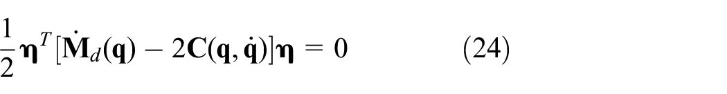
Combining equations (17) and (18), error equation of the closed-loop system is derived as:

Auxiliary signal is defined as:

where α > 0 is a given constant.
Substituting the derivative of equation (20) into equation (19) yields:

Lyapunov function is designed as:

Derivation of equation (22) can be obtained as:

According to the dynamic characteristics, one obtains 25 :
Then, equation (23) can be simplified as:

Set a function as:

where γ > 0 represents a given constant, which reflects the system’s ability to suppress disturbance signals,

where r1 and r2 are the weighted coefficients, both of which are greater than 0.
Substituting equation (25) into equation (26) yields:

According to equation (28), the feedback control rate is designed as:

where


where α1 > 0, ε > 0, β > 0 are given constants, ρf is the upper bound of model uncertainties.
Stability analysis
Based on nonlinear dynamic compensation, the trajectory tracking problem of the 6-DOF robotic crusher can be transformed into a proof of the asymptotic stability. Substituting equation (29) into equation (28) yields:

Assume that:


where
Substituting equation (26) into equation (33) yields:

Equation (36) can be simplified as:

According to the dynamic characteristics, one obtains:
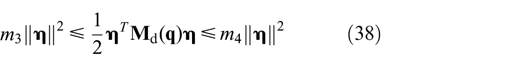
where m3 and m4 are given positive constants.
Then, equation (38) can be recast into:

According to equation (22), we have:

Assume that:


Combining equations (40)–(43), one has:


where λ1, λ2, λ3, and δ are given positive constants.
For any given initial state

where

Using the equation (46), we have:

Equation (37) can be rewritten as:

In view of Lemma 1, equations (44) and (51), one has:

where

Thus, the stability of the closed-loop system for the 6-DOF robotic crusher is proved. It can be seen from the equation (52) that the final values of

Disturbance suppression
In order to enable the 6-DOF robotic crusher to track the expected trajectory accurately, the system should not only guarantee the final value are bounded, but also have strong disturbance suppression ability when the external disturbance is added.
Equation (36) can be simplified as:
For any given positive constant T, we can get:

Equation (56) can be rewritten as:
Assume that:

where ε0 is the upper bound.
According to equation (57), one obtains:

To sum up, the proof of the disturbance suppression performance for the 6-DOF robotic crusher is accomplished.
Results and discussion
In this section, to verify the effectiveness of the proposed control scheme, numerical simulations of CTC, and the proposed robust control are compared. The co-simulation is conducted with MATLAB/Simulink and ADAMS. The MBS model is firstly established in ADAMS to obtain the output parameters (x, y, z, α, β, γ) of the system equations. Then the output information of ADAMS is read by MATLAB, and the control scheme can be established. Finally, data exchange is carried out between ADAMS and MATLAB. The system equations are solved by ADAMS solver, and the control equations are solved by MATLAB. They complete the calculation of the whole control process together. The schematic representation of the research workflow for robust control can be shown in Figure 5. The design of CTC is expressed as:


A schematic representation of the research workflow for robust control.
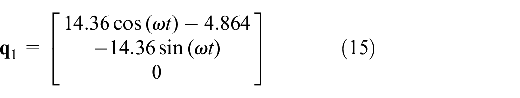
According to (60), the block diagram of CTC can be shown in Figure 6. According to (18) and (29), the block diagram of robust control based on dynamic compensation is shown in Figure 7. Two conditions for simulation are given as follows. The desired tracking trajectory of the 6-DOF robotic crusher is given by equations (15) and (16), where t ∈ [0, tm], and tm=20(s). The parameters of PD control term are set as Kp = 100, Kd=100. The structural parameters are selected as, M=182 kg, IX=3.45 × 10⁶ kgmm2, IY=3.45×10⁶ kgmm2, IZ=5.09×10⁶ kgmm2, m1= 1.87kg, m2=0.35 kg, s1=121.13mm, s2 =112.48mm, h=273.93mm, h1 = 103.9 mm. The tunable parameters of robust controller are set as α = 50, α1 = 10, β = 1, γ = 1, r2 = 0.1, ε = 0.01, ρf = 2000.

Block diagram of CTC.

Block diagram of robust control.
The trajectory tracking errors of the CTC and robust control are given in Figure 8. We can state that both controllers can successfully track the desired trajectory. But the tracking precision of CTC is unsatisfying, and the system error of robust control is converging to a small value close to zero. The main reason is that the control performance of CTC highly depends on dynamic compensation. Moreover, results of the trajectory tracking are presented in Figure 9. It can be found that the trajectories of the robust control are closer to the desired trajectory. Simulation results fully demonstrate the effectiveness and satisfactory performance of the proposed method in the case of model uncertainties.

Trajectory tracking errors by CTC and robust control: (a) tracking error along X axis, (b) tracking error along Y axis, (c) tracking error along Z axis, (d) tracking error around X axis, (e) tracking error around Y axis, and (f) tracking error around Z axis.
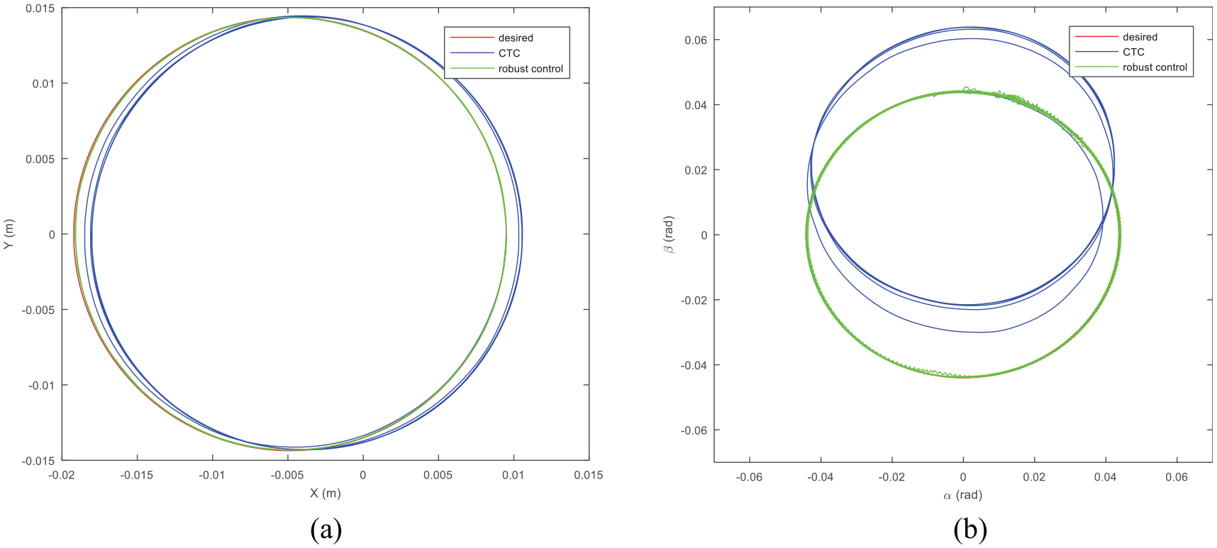
Results of the trajectory tracking: (a) trajectory tracking between X and Y and (b) trajectory tracking between α and β.
The numerical simulations are implemented by the co-simulation of ADAMS and MATLAB/Simulink, which includes ADAMS model and the algorithm. To demonstrate the effectiveness of the proposed design, we verify the simulation results from the above two aspects. On the one hand, the dynamic results of Lagrange method and ADAMS are compared. It can be found that the calculated and simulated outputs have good agreements which indicates the ADAMS model is reliable. 14 On the other hand, CTC is a well-known algorithm, which can be usually analyzed by numerical simulations and has been verified by experiments.26–29 Since the numerical simulation method of the proposed robust control is the same as CTC, the effectiveness of the algorithm is verified.
In order to better illustrate the good tracking performance of the robust controller, the external disturbance (10 sin(ωt), 15 cos(ωt), 10 sin(ωt), 15 cos(ωt), 10 sin(ωt), 10 sin(ωt)) is added. The results of the trajectory tracking are presented in Figure 10, which can state that the tracking accuracy is still satisfying. In other words, the robust controller can guarantee the convergence of tracking errors under the model uncertainties and external disturbances. Different results can be obtained when the amplitude changes, and the same results can be obtained when the frequency changes. The reason is that the upper bound of (52) contains the norm of the external disturbances, which depends mainly on the amplitude and is less affected by the frequency. In summary, simulation results show that the proposed strategy is very useful for effectively tracking the desired trajectory of the 6-DOF robotic crusher in the uncertain environment.

Results of the trajectory tracking with external disturbance: (a) trajectory tracking along X axis, (b) trajectory tracking along Y axis, (c) trajectory tracking along Z axis, (d) trajectory tracking around X axis, (e) trajectory tracking around Y axis, and (f) trajectory tracking around Z axis.
Conclusions
In this paper, a robust control method of the 6-DOF robotic crusher based on dynamic compensation is proposed for the stabilization control of uncertain systems with nonlinearities and disturbances. According to the virtual work principle, the dynamic model is presented by Lagrange method. By employing Lyapunov stability theory, sufficient conditions that guarantee the robustness of the system are obtained. Moreover, the disturbance suppression ability is analyzed by using dissipative inequality. Furthermore, simulation results of robust control are compared with CTC, which illustrate that the proposed method can achieve better trajectory tracking accuracy for the 6-DOF robotic crusher. The proposed method relies on the complete information about the state of the 6-DOF robotic crusher. To remove this restriction, extended state observer can be considered to estimate the state of the system and the real-time action of unknown disturbances. In the future research, auto-disturbance rejection control and the flexibility of the system for the6-DOF robotic crusher will be included.
Footnotes
Handling Editor: James Baldwin
Declaration of conflicting interests
The author(s) declared no potential conflicts of interest with respect to the research, authorship, and/or publication of this article.
Funding
The author(s) disclosed receipt of the following financial support for the research, authorship, and/or publication of this article: The authors would like to thank the financial support from the National Key Research and Development Program of China (Grant No. 2016YFC0600805).