
Abstract
This paper presents the prototype design, implementation and testing of a thermoelectric generator unusually applied to the fireplace stoves. The tested low-cost thermoelectric generator can be used as an alternative low source of electricity in areas with limited access to public electricity networks. Moreover, inclusion of a thermoelectric generator in the fireplace stove structure is novelty and interesting accessory in offer for customer. This study focuses on testing and determining the output values of voltage and current of the initial design using the natural and forces air cooling. The results are obtained by developed measuring device for that testing. The low-cost thermoelectric generator provided the power of 1.5 W at temperature difference 94°C using forced air cooling. Thus a thermoelectric generator prototype design is suitable for powering LED lighting and fans or recharging a mobile phone battery.
Keywords
Introduction
Alternative sources of electricity generation are currently receiving increasing attention to reduce the atmospheric and environmental impacts. Such sources include mostly wind and hydro power plants, photovoltaic systems as renewable energy sources. Promising alternative energy sources are thermoelectric (TE) energy converters that use waste heat to generate electricity.
Almost every production and energy consumption process is associated with the generation of a certain amount of heat. One way in which the produced waste heat can be utilised is via its direct conversion from thermal energy to electric energy through TE devices (generators), which operate on the principle of TE phenomena. Devices based on TE phenomena are characterised by ease of construction with no moving parts, soundless operation without chemicals, high reliability, minimal maintenance and long life time. 1
The principles and industrial applications of TE generators (TEGs) and energy harvesting devices have been studied for more than two-hundred years. Generally, the term TE phenomenon refers to the direct conversion of thermal energy into electrical energy and vice versa. This phenomenon was first reported through experiments in the mid-18th century by F. U. T. Aepinus (1724–1802).2–4 He observed that an electrical voltage is generated in a circuit assembled with two different conductors if the connections of the conductors are exposed to different temperatures. The magnitude of this TE voltage is primarily dependent on the temperature difference between the two connections and the material of the conductors. The resulting TE voltage reaches only a few microvolts per degree Celsius. The TE phenomenon is the fundamental principle of the Seebeck effect (discovered in 1821), the Peltier effect and the Thomson effect.3–5 First devices based on the physical TE phenomenon observed in solids were developed in the first half of the 19th century.
TEGs consist of a set of TE modules inserted between two heat exchangers.6,7 Each TE module is further composed of several 10 to 100 pairs of TE couples (of p- and n-type semiconductors) connected together electrically in series and thermally in parallel. They directly convert a part of the thermal energy that passes through them into electricity.6–8 The pairs of TE couples are typically sandwiched between two thin ceramic plates providing a platform to create both the electrical junctions and thermal interfaces. 2
The TEGs can be applied in many areas, for example, space exploration, automobiles, ships, locomotives, buildings, decentralised domestic power and microelectronics, etc.5,6,9–11 Additionally, such a generator can also be used to power a light or a radio, charge a mobile phone, or meet other requirements.
Considering opportunities and advantages of TEGs, a production company manufacturing fireplace stoves decided to develop a unique offer of its product as innovation that is a necessity for all industries today. Innovation can help managers provide unique solutions and products and thus gain an advantage over their competitors.
In field of TE phenomenon and TEGs, the research and development is focused on new TE materials, new designs, applications and along with it the simulation of performance of that devices. The use of new TE materials with a large ZT (figure of merit expressing the efficiency of TE materials) can revolutionise applications of TE devices in various fields.5,7,9,12 The dimensionless parameter ZT is as follows:

where α is Seeebeck coefficient, V/K, σ is electrical conductivity, 1/Ωm and κ is thermal conductivity, W/mK and T is temperature, K. The approaches to increasing the thermoelectricity is challenge for material scientists and it is essential for increasing efficiency and range of applications. However, the TEG system design and not only its material significantly influences the power generation potential of a TEG. 8
The heat propagation and generation inside the TE module can be predicted by solution of simple one-dimensional heat conduction equation (analytical models) that describes the transfer and generation of heat throughout a TEG. Steady-state and transient solution of one-dimensional heat conduction equation regarding the boundary conditions and initial state is in Montecucco et al. 13
The behaviour of a TE system can be described by the following three-dimensional governing equations which include the thermal and electrical fields:


where
The numerical analysis using simulation tools with finite elements is suitable for three-dimensional complex thermoelectric simulation. The system of finite element equations can be obtained by applying Galerkin procedure to the equations (2) and (3) in association with the boundary conditions. 16
Various applications and potential uses of TEGs have been investigated, however there are only several studies on TEG powered by the fireplace stove. Thus, the study in paper is contribution to expand the use of TEGs for fireplace stoves to achieve an efficient and cost effective design alternative. Thus the paper provides mainly the experimental results obtained by original made measurement devices and corresponding TEG design applied to not frequent heat source, that is, fireplace stoves.
Design of the TEG
This study aimed to design, implement and maintain an affordable and accessible TEG for a special type of fireplace stove. The low-cost commercial TE module TEC 27145 SP1848 was selected. The current and voltage values specified by the producer are 225 mA and 0.97 V for ΔT = 20°C and 669 mA and 4.8 V for ΔT = 100°C. It is a Peltier plate module, intended for cooling and/or heating applications. The maximum temperature that can be applied to this TE module is Tmax = 150°C.
The principle of the TEG structure does not differ significantly for each individual design. Figure 1 illustrates the proposed design consisting of the layered structure of TE modules that are sandwiched between heater and cooling blocks through steel and aluminium alloy heat-spreading plates. The proposed TEG design is powered by four TE modules as the performance of the TEG can be improved by the use of several TE modules in design.

Layered structure of TEG (without fan-assisted cooling).
The simple construction and assembly, maintenance-free operation and low costs are advantages of such design proposal. Further, the passive cooler (aluminium alloy pad, Figure 1) can be manufactured in one production site as the fireplace stove. The cooler does not have to be outsourced or purchased. However, the disadvantage of this design is the possibility that the passive cooler could dissipate heat inefficiently and the required temperature difference could not be ensured. This could overheat the TE module and lead to subsequent damage.
The forced convection of water cooling would create a higher temperature difference. However, the difficulty of the water connection is a disadvantage. In addition, a water container – exchanger and a circulating pump with an electrical connection would be required. The construction and implementation of such design would be significantly difficult with high costs, complicated assembly and required operational maintenance.
Considering the advantages and disadvantages of natural and forced convection of air and water cooling in terms of low production costs, ease of design and assembly on the fireplace stove, expected output parameters and maintenance-free operation, alternative of four TE modules in the TEG using air natural convection by an aluminium alloy cooler was selected for the experimental testing of that initial design.
A CAD model of the design was realised using the Solid Edge software. Based on this model, a prototype of the generator was manufactured and mounted on a fireplace stove. The experiments described in following section were performed to confirm the functionality of the initial design and to identify any defects and imperfections.
Testing – implementation, measurements and results
Measurement 1 – TEG placement
In order to achieve the maximum efficiency of air-cooled natural convection in the TEG, it was necessary to realise the largest possible heat sink between the heated side of the TE module and the naturally air-cooled side. Therefore, we identified a place on this fireplace stove that was heated to the highest possible temperature in order to ensure the largest possible temperature difference ΔT.
To find the most suitable position on the fireplace stove, the temperature was measured at three selected locations: (i) position A on the side column of fireplace stove, (ii) position B on the top plate and (iii) position C on the back plate (Figure 2(b)), using a digital thermometer with a VOLTCRAFT K204 data logger, which had a measuring range of −200°C to +1370°C and a significantly high accuracy.
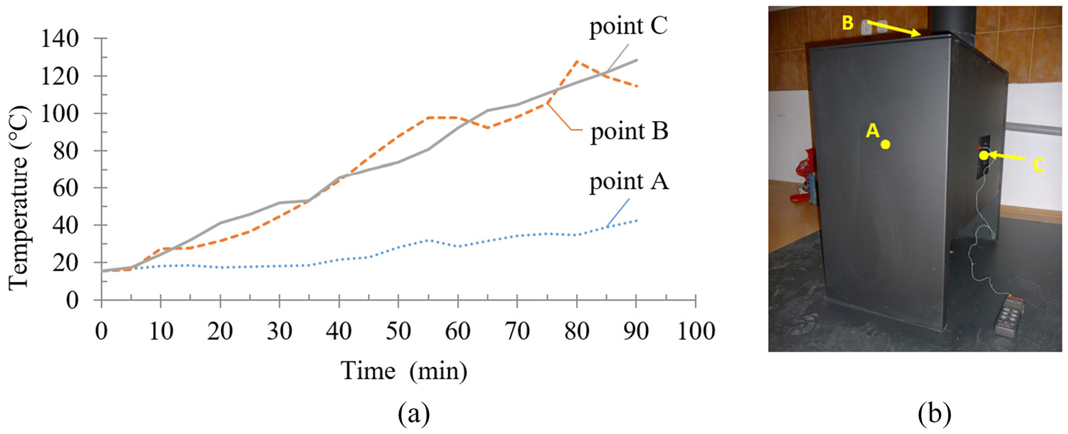
Increase in temperature with respect to time (a) at positions A, B and C (b).
According to the results of measurement 1 (Figure 2(a)), position C was selected as the location of the TEG. Although position B (at the top plate) recorded temperature values similar to those of position C, it was not considered suitable due to lack of space between the individual components inside the fireplace stove. Moreover, this position B recorded a non-continuous temperature increase during heating. The TEG mounted on position C is shown in Figures 3(a) (CAD model) and 4(b) (photo).

(a) CAD model of TEG locations and (b) CAD model of the designed TEG.
TEG components and implementation
According to Figure 3(b), the principal components of the designed TEG are as follows:
Pad. Its main task is to ensure the transfer of heat from the outer surface of the hearth chamber to the plate on which the TE modules are placed. An aluminium alloy was selected due to its high thermal conductivity, good machinability and lower cost comparing to other materials of high thermal conductivity. The shape and dimensions of the aluminium alloy pad was designed to arrange four TE modules. Four holes for fixing screws to mount that component to the fireplace plate are also included. The cooler and the pad are mounted by four other screws to reduce the thermal bridge effect of fixing screws.
TE modules (four connected in series) with above mentioned parameters. The dimensions of one TE module are 40 × 40 × 3.3 mm.
Passive cooler. This absorbs heat through the fins and dissipates it by natural convection to the surroundings. The cooler is made of aluminium alloy because of mentioned high thermal conductivity.
Proper functioning of the TEG is ensured by the following additional components:
The value of the electric voltage generated by the TEG is not always same and varies over time due to temperature fluctuations; thus, a DC/DC converter is needed. A DC/DC voltage converter that can change the DC voltage value at the input from 3.5 to 12 V to another DC voltage value (greater or lesser) at the output from 1.2 to 24 V is used.
Thermal interface grease material (Figure 1) helps maximise heat transfer on the individual sides of the TEG and TE modules. The contact surfaces do not ideally have a flat and smooth surface. Despite being polished, real surfaces include ‘peaks’ and ‘valleys’ of roughness. Therefore, there exists a layer of air between them when an interface material is not used. Because air is generally a poor conductor of heat, active surfaces are covered with a thermally conductive grease to improve heat transfer and thus increase the overall efficiency of the device. The grease is made of a silicone material that contains a large amount of thermally conductive metal oxides, thus ensuring high thermal conductivity and thermal stability.
Measurement 2 – testing of developed measuring device
Having assembled and mounted the TEG at back side of fireplace (Figure 4(b)), the testing could be performed (Figure 4(a)). Owing to the large number and complexity of measuring quantities, a measurement set (Figure 4(b)) with a developed measuring device was assembled to measure the required quantities simultaneously and reliably.
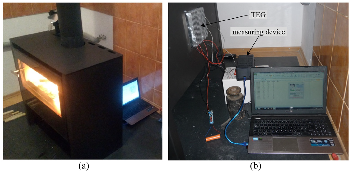
Testing of TEG: (a) front view and (b) detail of measurement.
The interior of the measuring device is shown in Figure 5(a). The measuring device consists of an Arduino UNO microcontroller board with installed program to allow writing and uploading of source codes in a real-time work environment. The sensors on the microcontroller board were two temperature sensors, corresponding to K-type thermocouples with a MAX 6675 controllers for measuring temperatures T1 and T2 of the heated side and the cooler of the TEG, respectively, and a current and voltage sensor MAX 471. The block diagram is shown in Figure 5(b).
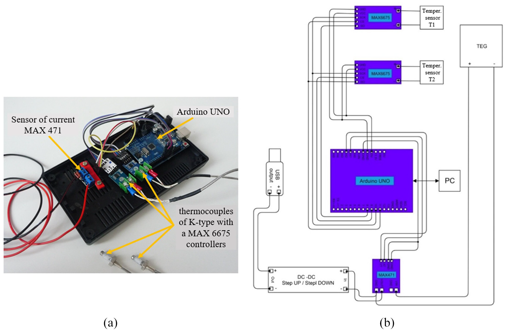
Inside of measuring device and block diagram – input from TEG and output to DC/DC voltage converter and connection to USB output.
A program created in open source software platform an Arduino IDE (Integrated Development Environment) was uploaded to the board. This software is written in JavaScript for easy editing and setup. It can easily be run on commonly available computers and load on the microcontroller board.
The created program contains commands for control, communication and obtaining information from individual sensors, as well as for listing the measured values of temperature, electric current and voltage in graphical form. The actual electrical power, W, was calculated using the following equation:

Individual measured values can be displayed in real time using a serial port monitor or a serial recorder. Owing to the complex processing involved when recording a large set of values, the program was modified so that the measured data were recorded directly into a Microsoft Excel sheet (Figure 6) and for better visualisation transformed into graphs.

Measured values recorded directly in Microsoft Excel.
The input/output of the TEG was connected to the measuring device. After initial heating of fireplace, the measuring device started to record the values obtained from the individual sensors every minute.
First, the no-load voltage Uc was measured, that is, without current consumption from the source, I = 0. That initial test of the TEG was used for confirming the accuracy and reliability of the developed measuring device as well as the correctness of the TE module manufacturer data.
The highest measured no-load voltage value for the four TE modules connected in series is Uc = 9.576 V at a temperature difference of ΔT = 63°C, as shown in Figure 7. Therefore, a single TE module can induce the following measured no-load voltage:


No-load voltage Uc and temperature difference ΔT curve.
The manufacturer of the TE module states that with a temperature difference of ΔT = 63°C, the voltage value on the TE module should be U = 2.4 V. The measurement achieved a very similar value with difference only 0.25%. The reliability of developed measuring device is very high.
Comparison between natural and fan-forced cooling
A load was connected to the output of the TEG when measuring the current and power. For the first 34 min of the measurement, a simple LED strip light source was connected to the TEG using the natural cooling by ambient air (Figure 8). Then the load was represented by a two-bladed commercial fan intended to circulate heat from the fireplace to the room. The fan was used to force cooling an aluminium alloy cooler. It is evident that the connected fan cooled the TEG and thus increased the temperature difference and magnitude of the generated current and power. The obtained power was approximately three times greater (1.47 W) when using fan-assisted cooling as compared when using natural cooling (0.49 W). Options for increasing the temperature difference when a simple air natural convention is already used, according to Gao et al. 1 and Winczek 15 , are the use of water natural convention or the forced cooling by air or water. We confirmed that forced cooling is very efficient.

Power and current versus time with connected LED strip and fan.
Testing of mobile phone charging
The designed TEG with the natural air-cooling system was subjected to a phone charging test, which was one of the study objectives. A battery with a capacity of Q = 2000 mAh and a voltage of Ub = 4.2 V was used for testing. This battery was connected to the TEG for 1 h. At the beginning of the test, a voltage of Ub1 = 2.5 V was measured by a multimeter as the battery was not completely discharged.
The graph in Figure 9 shows the generated electric current Ip recorded with time t. The time dependence is characterised by the current fluctuations, which are caused by the DC/DC converter, as it charges the battery in the form of current impulses. Moreover, they could also be caused by the temperature fluctuations on both the heated and heatsink sides and the corresponding variable temperature difference ΔT.

Time dependence of generated output electric current.
According to Figure 9, the average current value supplied from the TEG is

After the 1-h test, we measured the battery voltage again and the measured value was Ub2 = 2.75 V. It was clearly evident that the battery was being charged; however, during charging, the value of the battery voltage increased by only 0.25 V. According to equation (7), we can determine the time required to theoretically charge the mobile phone battery to the maximum voltage value using the designed TEG device without additional forced cooling:

where t is the charging time, h, Q is the capacity of the battery, mAh and I is the generated charging current, mA. Using equation (7), we found that with the output parameters of the designed TEG, full charging the battery to the maximum voltage value would take about 14 h, which is a relatively long time.
Discussion
We achieved a power of 0.5 W and 1.5 W at a temperature difference of 63°C and 94°C using natural air-cooling and forced air cooling powered by the TEG itself, respectively. The total material cost for the production of TEG was 43 euros.
The amount of power is consistent with review in Gao et al. 1 which provides that the performance of a stove-powered generator ranging from 1 W to 10 W. However, we had unusual application of TEG to fireplace stove.
A TEG initial design using air natural convection cooling is suitable for powering LED lighting and fans that are either for forced cooling of the TEG or to ensure uniform temperature distribution in a room, etc. A possible solution to reduce the time required to recharge the battery is to improve the output values of the electrical voltage and current produced by TEG.
The output parameters can be improved by creating a higher temperature difference ΔT between the heated side (aluminium alloy pad) and the cooled side by lowering the temperature on the cooled side as follows:
with additional forced air-cooling by means of an axial fan that is supplied by the TEG itself,
creation of water-cooling module with natural or forced convection; there are additional electrical energy requirements what would complicate the construction and increase the cost.
An alternative with fan-assisted air forced convection cooling was tested. The cooler side temperature reached a lower value than with a passive aluminium alloy cooler, as shown by the comparison of the thermal camera FLIR T425 measurements in Figure 10. By selecting and comparing the temperatures at the points at the middle of aluminium alloy cooler, for example, point Sp6 in Figure 10(a): 85.1°C and point Sp4 in Figure 10(b): 54.3°C, a temperature is approximately 31°C lower by forced cooling with a fan. This means that a temperature difference between fireplace stove back plate and cooler is 49% larger (before ΔT = 63°C, now ΔT = 94°C).

Temperature distribution: (a) without fan assisted cooling and (b) fan assisted cooling.
Based on the presented measurements, a simple improvement in the original TEG design provides improvement of output values. The original initial design with a passive aluminium alloy cooler should be supplemented with two commercial axial fans mounted on the top of a passive cooler. This new TEG design is shown in Figure 11(a). These fans would be powered by the TEG itself. However, with this connection, no electrical energy would remain, for example, to charge the mobile phone battery. The TEG structure should be enhanced by additional four TE modules connected separately in series of two, supplying only cooling (Figure 11(b)). The original four TE modules in series would recharge the battery or to power the light source.

TEG design alternatives for improved output parameters.
Another alternative to improve the output parameters of the TEG is to use TE modules of higher performance, which can provide higher electrical voltage and current values under described conditions. However, the costs would increase.
Considering the research, new TE materials of higher efficiency based on nanostructure engineering are developed. In 2010–2017, the search for new TE materials was growing exponentially. 16 TE materials have the specific capacity of converting a flow of heat into electrical energy (Seebeck effect) and vice versa (Peltier effect). 17 Naturally, the non-conventional TE materials provide higher figure of merit ZT but are difficult to manufacture and more expensive.
Conclusion
The tested designs of low-cost TEG are implemented directly on the fireplace stove and can be used as an alternative weak source of electricity in areas where access to the public electricity network is difficult or impossible, for example, a cottage in a forest. In general, the TEG can be presented as a novelty of fireplace designs, and it can provide interesting offers for customers with fireplace stoves. The proposed TEG is intended to power LED lighting strip as a design backlight for this fireplace or for weak recharging of mobile phones. The main advantages of the design solution include simplicity of design, simple assembly, in case of natural air convection it is without moving parts, which guarantees a long service life, thus reducing the need for maintenance. Even the proposed design satisfies the essential condition of the lowest possible economic costs. The TEG in paper was used to charge a mobile phone battery; however, the time required to fully charge it was relatively long. In this paper, the proposed improving solutions can improve the output values of voltage and current of the designed TEG.
The secondary outcome of the paper is developed measuring device and its description intended for efficient and reliable testing of output values (temperatures, voltage, current and power) of the tested TEG.
Our results on natural and forced air-cooled TEGs are promising for future studies on lower power systems. The output TEG parameters should be improved through an effective cooling system, advanced materials of TE modules, the development of a system controlling power fluctuations, the numerical simulation of effective temperature distribution of fireplace stove and chimney pipes, while considering cost-effectiveness, life time, noise and reliability.
Footnotes
Handling Editor: James Baldwin
Declaration of conflicting interests
The author(s) declared no potential conflicts of interest with respect to the research, authorship and/or publication of this article.
Funding
The author(s) disclosed receipt of the following financial support for the research, authorship and/or publication of this article: The authors would like to thank the Agency of Ministry of Education, Science, Research and Sport of the Slovak Republic for supporting this research through the grant of VEGA 1/0910/17. This work was supported by the Slovak Research and Development Agency under Contract No. APVV-18-0316.