
Abstract
The aim of this work is to investigate the effects of direct-current electric fields on the behavior of the small-scale diffusion ethanol flame. The flow rate of liquid ethanol, the flame temperatures, and the flame shapes were measured. The results showed that the stable working ranges of a small-scale combustor became narrower under the direct-current electric field. The main reason was that the evaporation velocity of liquid ethanol limited by great heat loss effect cannot keep up with the increasing of combustion velocity by the ionic wind effect. The movements of those charged particles in flame enhanced the combustion process, resulting in higher flame temperatures under positive or negative direct-current electric field. The flame heights decreased with increasing applied voltages, due to the ionic wind effect increasing the flame temperature and the diffusivity. The flame voltage–current characteristic was also examined. Three regions can be divided: the subsaturation region, the saturation region, and the supersaturation region. Finally, the ratios of electric active power to actual burning thermal power of ethanol flame were calculated. It can be inferred that using the external direct-current electric field with little power consumption to control combustion and flame is a feasible method.
Keywords
Introduction
The micro energy systems have received great attention in the past decade.1–3 There are many experimental and numerical studies on micro-combustion system, including flame shape,4–6 flame stability,7–10 flame temperature, 11 and developments of new burners.12–14
Many micro-combustors were designed using hydrogen or some hydrocarbon as fuels.15–18 Some researches preferred to apply liquid hydrocarbon fuels due to their advantages, such as big energy density, compactness, and portability.19–24
The hydrocarbon flame contains a large number of ions and electrons with a number density of 109–1012/cm3 due to chemi-ionization in the reaction zone, which will put an effect on the combustion behavior.25–27 So, the electric field can be applied to reduce instabilities, adjust flame luminosity, and control combustion efficiency and emissions. Marcum and Ganguly 28 found that positive electric field could significantly alter the flame structure and increase the flame propagation velocity with applied direct-current (DC) electric field above the propane–air premixed flame. Borgatelli and Dunn-Rankin 29 observed a small diffusion methane–air flame burning between two planar gauze electrodes. The fuel rate was in the range of 20–60 mL/min. They analyzed the electrical behavior as part of an electrical circuit for control by designing a fairly simple proportional–integral–derivative (PID) control algorithm. Ata et al. 30 experimentally studied the stability enhancement of conical premixed flames by application of DC electric fields and found that the pronounced effects were observed for the turbulent flames stabilized at the tip of a circular cylindrical bluff-body flame holder. Prager et al. 31 presented the simulations of charged species concentrations along a premixed flat methane–oxygen flame and concluded that the ionic reaction mechanism is still incomplete. Flame stabilization and extinction in a number of different flows can be affected by application of electric fields. Electrons and ions are present in flames, and because of charge separation, weak electric fields can also be generated even when there is no externally applied electric field. 32 A theoretical and numerical model for ionized methane–air flames was developed to predict the electric currents based on the charged particle distribution in the flame. 33
The effects of electric fields on flames and resulting currents are not well understood and relatively unexplored. Carefully performed and well-documented experiments are of utmost importance to broaden our knowledge. However, the effects of DC electric fields on small-scale flame behavior using liquid ethanol as fuel have seldom been investigated. The liquid fuel often needs to be evaporated before ignition and combustion. The evaporation of liquid fuel in small-scale combustor may be affected greatly by heat loss. So, the liquid fuel flames may present different behaviors from the gas fuel flames even under the same DC electric field, such as the different characteristics of combustion stability.
Consequently, this article focused on studying the behavior of laminar diffusion ethanol–air flames when subjected to DC electric fields with three different electrode spacings over the voltage ranges of −5 to 5 kV. In particular, this article applied different voltages at different fuel flow rates to investigate the combustion stability. And the flame temperatures and shapes were also measured under the stable combustion condition at a very small flow rate of 1.2 mL/h. The voltage–current characteristic (VCC) was analyzed to find a suitable range of the applied voltage. Finally, the external electric power was calculated in order to prove the possibility of controlling the combustion and flame in small scale by external DC electric field.
Experimental description
Test section
Figure 1 shows the schematic diagram of test section. A stainless steel tube was used as a burner nozzle and was supported and kept perpendicularly by a ceramic base. The nozzle has an inner diameter of 0.9 mm, an outer diameter of 1.2 mm, and a length of 10 cm.

Test section.
The liquid fuel was pure ethanol (CH3CH2OH, molecular weight of 46.07, purity > 99.5%), which was ignited at the outlet of the nozzle, forming the small diffusion flame in the quiescent air at room temperature and atmospheric pressure. Under stable combustion condition, the liquid ethanol absorbed the released heat from flame and was vaporized in the nozzle nearer to the outlet. The flow rate of ethanol was accurately adjusted to avoid overflowing outside the nozzle.
Experimental setup
Figure 2 shows a schematic diagram of the present experimental setup. It consisted of a fuel supply system, a test section, an external DC electric field system, an optical visualization system, a current and temperature measurement system, and a data acquisition system. The liquid ethanol was accurately controlled and pushed into the burner nozzle by a syringe pump (KDS 100; KD Scientific; USA) with an uncertainty of 1.0%.
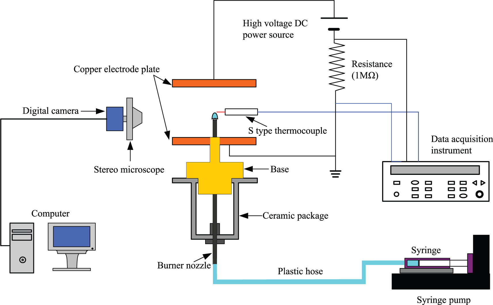
Schematic diagram of the experimental setup.
The external DC electric field system consisted of a DC power supply (71030P; Boher HV; China) and two copper plate electrodes with a diameter of 80 mm. One was put on the outlet of the ceramic package, and another one was located on the top of the flame. The electrode spacings were adjusted and kept at a certain value of 4, 5, and 6 cm in experiments. The electric field strength E was obtained by adjusting the DC voltage output U and the electrode spacing D. When the base electrode was connected to the anode of the DC power supply, the direction of electric field is the same as the direction of fuel jet, which was called as positive electric field as shown in Figure 3(a). While on the contrary, it was defined as the negative electric field as shown in Figure 3(b).

Schematic diagram of electric field directions: (a) positive electric field and (b) negative electric field.
The electric field distribution between the two electrodes was simulated by ANSYS Maxwell 2D software. Figure 4 shows the equipotential lines and electric field strength between the two electrodes with different spacings. When the electrode spacing became smaller, the electric field strength would become greater. The nonuniform electric field distribution mainly appeared near the edge of electrodes. The electric field distribution in the central section between the electrodes where the flame located was uniform and the electric field strength was nearly constant with the changing of the electrode spacing.

Electric field between the two electrodes with different spacings: (a) D = 4 cm, (b) D = 5 cm, and (c) D = 6 cm.
The flame shapes were visualized by the charge coupled device (CCD) camera (Jenoptik ProgRes C3 cool, 2080 × 1542 pixels; Jenoptik Group, Germany) combined with a stereo microscope (SEZ-300; Finial Company, Shenzhen, China). All flame images were transferred and stored in the computer by the data acquisition system. The dimensions of all flame images were determined from contours of peak blue luminosity as shown in Figure 5(a), which can be calibrated by Origin software with an allowable error of ±0.01 mm.

Flame height and temperature measurement methods: (a) flame height and (b) flame temperature.
The temperature of flame top was measured with an S-type platinum–rhodium thermocouple as shown in Figure 5(b). An S-type platinum–rhodium thermocouple with the node diameter of 0.3 mm was used to measure the flame temperature. A standard resistance of 1 MΩ was connected into the loop, as shown in Figure 6. And the electric current was calculated by the measured voltage across the resistance. In order to avoid the interference between the thermocouple and electric field, the flame temperatures were measured first. Then, the voltages were measured after taking away the thermocouple. The effect of electric field on the flame temperature measurement was ignored due to extremely small ion current in the present experiments.
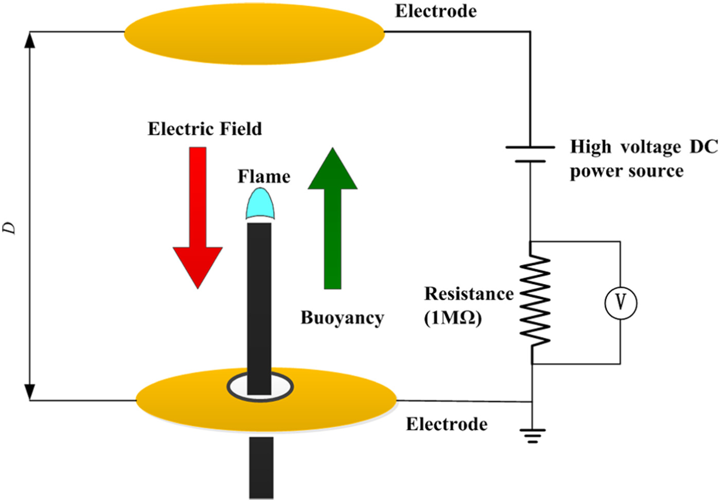
Simplified model of the vertical electric field and circuit.
When the flow rate changed from one value to another, the thermocouple should be moved to the new flame top position to obtain the flame front temperature. Through the thermocouple temperature correction for radiation heat loss, it obtained a more accurate value of flame temperature measurement, which has a standard error less than 10 K. During the present experiments, a noncontact method was also tried to use. An infrared (IR) flames pyrometer (IS 5/F; IMPAC; Germany) was applied to measure the flame temperature. But it was found that it did not work well on the blue ethanol flame maybe due to very few soot particles in it. So, it was thought that the flame temperature measurement by thermocouple with suitable correction was reliable and accurate. All flame front temperatures were measured at least five times and calculated the average values under stable combustion conditions. Future work needs to find more accurate method or apparatus to measure the flame temperature.
All these signals were transferred to a computer by the data acquisition instrument (Agilent 34790A). All experimental data were recorded after the flames reached steady states.
Data reduction
The sizes of the flame height

The flame height was calculated by

Since the current was too small to be measured accurately, a resistance (R = 1 MΩ) was connected into the loop in order to estimate the loop current, I, by measuring the potential difference across the resistance by the data acquisition instrument. According to Ohm’s law, the electric current can be calculated

Compared with the flame resistance, the resistance connected in the loop is so small that the effect on the loop current by the resistance can be ignored.
Error analysis
The liquid fuel used in this study was pure ethanol (C2H5OH, with purity of 99.5%), and its physical properties are shown in Table 1. The experiments were conducted in the following variation ranges of operating parameters: liquid ethanol flow rate Q of 0–2.5 mL/h; applied voltage of −5 to 5 kV; and the electrode spacing of 4, 5, or 6 cm. The measurement errors of a set of parameters are listed in Table 2. Performing the standard error analysis, the maximum uncertainty of electric current in the loop was ±0.5%. The maximum uncertainty of the flame temperature was within 5% after correcting the heat loss.
Physical properties of liquids.

Uncertainty analysis.

DC: direct current.
Results and discussion
Combustion stability
It was found that the flames of liquid ethanol only could maintain a stable combustion condition within a certain range of the flow rates during the present experiments. When the flow rate was too low, ethanol could not be ignited or easily quenched during the combustion process and could not maintain a stable combustion condition. The lower stability limit (Q min) was defined as the smallest flow rate that the ethanol can be ignited and combusted stably. When the flow rate was too high, the stable flame changed from light blue to yellow, and the flame length varied periodically accompanied by periodic sounds and finally came into oscillatory flame condition. The upper stability limit (Q max) was defined as the biggest flow rate that the ethanol can maintain the stable combustion condition.
Four modes of the small-scale diffusion ethanol flames under different flow rates without any electric field were observed during the present experimental process, namely, quenching flames, stable flames, quasi-oscillatory flames, and oscillatory flames, as shown in Figure 7. These four modes had also been observed under positive electric field and negative electric field.

Four modes of diffusion flames at different flow rates without electric field: (a) quenching flame, (b) stable flame, (c) quasi-oscillatory flame, and (d) oscillatory flame.
The stability limits under DC electric fields with different electrode spacings, 4, 5, or 6 cm, are shown in Figure 8. The upper stability limits (Q max) under positive electric field or negative electric field were all lower than that without any DC electric field. The upper stability limits (Q max) decreased with increasing applied voltage in the present experimental ranges.

Stability limits under DC electric fields with different electrode spacings: (a) under positive electric field and (b) under negative electric field.
Some studies showed that electric fields affected flames in three major ways: the thermal effect, the ionic wind effect, and the electrical–chemical effect. Several numerical simulations showed that the ionic wind effect dominated when there was DC electric field on flame behaviours.4,34,35
Ions can be found in most combustion systems using hydrocarbon fuels. 36 When external DC electric field was applied on flame, the large number of ions and electrons moved to the electrodes and ionic wind came into being. The ionic wind effect enhanced heat and mass transfer between the flame front and the unburned area, which increased the combustion velocity. In the present experimental system, liquid ethanol was used. For liquid fuel, it often needs to be vaporized before combusting. If the evaporation velocity can keep up with the combustion velocity, the flame will be stable when the dynamic equilibrium achieved. Under the present experimental conditions, the evaporation velocity could not be improved due to great heat loss effect and could not keep up with the increasing of combustion velocity by the ionic wind effect. So, the upper stability limits (Q max) decreased with increasing applied voltage.
When the fuel flow rate was very low, the quenching flames in the small scale were found mainly due to the thermal quenching caused by heat loss. The ionic wind effect increased the convection and heat loss. Thus, the lower stability limits (Q min) increased with increasing applied voltage. Thus, the electric field enhanced the combustion process which made the stable equilibrium more difficult to achieve and the stable working ranges became narrower.
Flame temperature
In order to investigate the effect of DC electric field on the flame temperature, a series of stable flames under the flow rate of 1.2 mL/h were selected to be analyzed. Figure 9 shows the measurements of flame temperatures under positive and negative electric fields with three different electrode spacings.

Flame temperatures at flow rate of 1.2 mL/h under different electric fields: (a) positive electric field and (b) negative electric field.
The flame temperatures increased first and then reached a certain value with the increasing voltages. It reached 1389.2 K under the positive electric field and 1376.7 K under the negative electric field. As we know, the flame of hydrocarbon fuel can be divided into three main regions: the transport preheating region, the first reaction region, and the second reaction region. In the transport preheating region, the fuel temperature rises sharply. In the first reaction region, the chemical reaction starts. And in the second reaction region, CO and free radical recombine. The highest density of ion and electron occurs in the first reaction region of flame. There are little charged components outside the reaction region, and the flame is neutral on the whole. So, the flame can be regarded as thin plasma, including a lot of positive charged ions and negative electrons.
Under DC electric field, the positive ions moved to the negative electrode, and the negative electrons moved to the positive electrode by the electric force, which made charged particles mix quickly with oxygen in the flame front. So, the movements of these charged particles could enhance the combustion process and resulted in higher flame temperatures.
The distributions of positive ions and negative electrons in the flame were different. So, there was a little difference between the behavior under positive electric field and that under negative electric field, and this showed a little difference in the flame temperatures. But the change trend of both was similar.
When the voltage increased to a certain value, the increasing acceleration of flow near the flame increased the flame heat loss at the same time, and it has more significant effect than that under lower voltage, which prevents flame temperature increasing further, so any increasing voltage did not produce a further rise in flame temperature.
But why was the trend of increasing very similar between the variations under positive electric field and that under negative electric field? It needed to be explained by the motion of charged particles, the field-induced electric body force, and ionic wind effect.
There were a large number of positive and negative ions being produced by chemi-ionization in the hydrocarbon flame reaction zone.37,38 The ions and electrons in the flame affected the combustion process. The variations in the flame temperature with the presence of the electric field were mainly due to the field-induced electric body force. The electric body force affects the flame through the interaction of electric fields and the flame ions which leads to the ionic wind effect.34,39
The electric body force F on the interface between the flame and the air can be expressed as equation (4). 40 It is consistent with the electric force reported by Drews et al. 41

where ε
1 is the permittivity of air,

Electric body force on the flame front.
The direction of electric field E was different, but the electric body force on the flame front was the same under the positive electric field and the negative electric field. So, the variation trend of flame temperatures was similar. The electric body force made the ions and electrons move, formed the ionic wind, improved the mixing of oxygen and ethanol, enhanced the combustion process, and increased the flame temperatures.
Flame shape
Flame shape or structure is an important characteristic of laminar diffusion flame. Figure 11 shows the images of flame shape obtained by a high-speed camera combined with a microscope. All these cases were carried out under the flow rate of 1.2 mL/h to keep a stable combustion condition and the electrode spacing of 4 cm.

Typical images of flame shape under different electric fields: (a) positive electric field and (b) negative electric field (Q = 1.2 mL/h, D = 4 cm).
In the present experimental process, a laminar diffusion ethanol flame formed first near the nozzle outlet without any electric field (U = 0). Then, a positive voltage was applied to the base electrode, and the flame started to be shortened slightly. The flame heights gradually decreased with the increasing applied voltage. The flame became smaller when the applied voltage was gradually increased. However, when a negative voltage was applied to the base electrode, changes of the flame shapes were not as obvious as that under positive electric field. But the variation trend was similar with that under the positive electric field. The flame lengths also decreased with increasing applied voltage. Figure 12 shows the changes of measured flame lengths under DC electric field with three different electrode spacings.

Flame lengths at flow rate of 1.2 mL/h under different electric fields: (a) positive electric field and (b) negative electric field.
The flame shape was sensitive to the surrounding flow field and the diffusion. As discussed by Gan et al., 42 the length of a steady, laminar diffusion flame is nearly proportional to Q/D, where D is the diffusivity. According to Fick’s diffusion law, D is nearly proportional to T 3/2. And according to the experimental measurements of flame temperatures and discussions in the section above of this article, the flame temperature T under electric field was higher than that without any electric field (U = 0), which was caused mainly by the electric body force and ionic wind effect. The electric field increased the flow rate by the electric force and promoted the burning rate and the diffusion of the components which made the flame length shorter no matter whether it was a positive or negative electric field.
Flame VCC
It was found that there was no electric current under the DC electric field before the ethanol was ignited. That is to say that there was an open loop without any flame. It was proved that the electric current was ion current due to interaction between the flame and external DC.
The electric field formed between the two parallel copper plate electrodes can be assumed as a one-dimensional vertical electric field. Because the nonlinear change of the electric field only appears at the location very close to the flame tip, the capillary tube brought very little effect on the one-dimensional assumption. The positive ions in the flame reached the negative electrode through the air gap by the electric body force and the negative ions and electrons reached the positive electrode. It formed an electric current in the whole loop. This relationship between ion current and electric potential is usually called as VCC. A resistance (R = 1 MΩ) is connected into the loop to indirectly measure the loop current accurately by measuring the voltage across the resistance. A simplified model of the electric field and the loop is shown in Figure 6.
The VCC curves can be used to show the flame response to actuation for varying applied voltages. Figure 13 shows the VCC curves under DC electric field with different electrode spacings of 4, 5, and 6 cm. All these VCC curves present three distinct regions using the same definitions in the previous studies:28,34
Subsaturation: the region is characterized by an increasing ion current from the flame with voltage applied;
Saturation: a plateau region, as the rate of ion generation is same as the ion removal under the DC electric field;
Supersaturation: a new current rise with the further voltage increase is observed in this region.
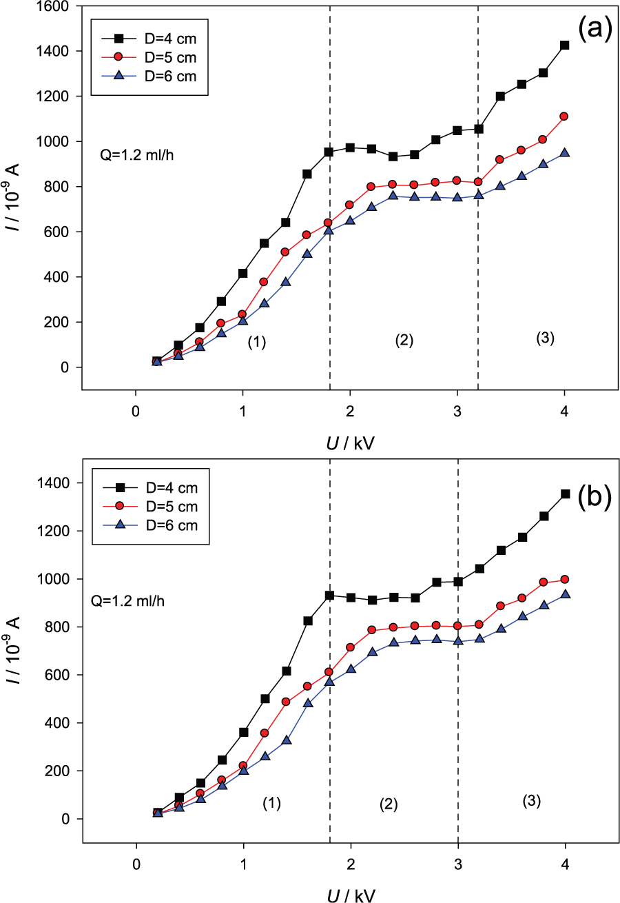
Flame VCC curves at the flow rate of 1.2 mL/h under different electric fields: (a) positive electric field and (b) negative electric field.
In region 1, there are a large number of ions, electrons, and molecules in the flame. Positive ions in the reaction zone are typically removed from the flame zone by ion–electron recombination. However, with the application of a DC electric field, a drift of positive ions occurs, reducing recombination and increasing the flow of charge across the applied potential gradient.
In region 2, by increasing the applied voltage, the rate of ion–electron recombination is reduced to a constant value resulting in a saturated ion current. 24 The flame reaches a dynamic equilibrium condition. The saturated ion current allows for a direct measurement of ion number density, which represents the maximum number of ions that can be produced by the flame as long as there is no appreciable change in flow conditions.
In region 3, when the voltage increases to a certain value, the electric field is sufficiently high to create a unipolar region, preventing ion–electron recombination in the region between the flame and the cathode. And the ions and electrons moved by the force of electric field entraining air, and it promoted mixture of reactants further which increases the burning rate and further increases the rate of flame ions generation by secondary ionization from high energy electron–neutral collisions. If the voltage is too high, as near 4500 V under positive electric field or −4800 V under negative electric field, the flame will be blown out finally, and there is no ion current in the loop and no flame could be observed.
From the discussion above, it can be concluded that the VCC and ion behavior in flame is not only of scientific interest but also represents a potential mechanism of active combustion control via external electric fields. It is suggested that the combustion and flame should be kept and controlled in region 2, the saturation region, to obtain a stable combustion condition and response to actuation. Based on the present experimental results, the suitable range of voltage is 1.8–3.4 kV under positive electric field and 1.8–3.0 kV under negative electric field. In terms of stable combustion situation, it could reach a higher temperature and keep a stable current in the loop (see region 2 in Figure 13) under the suitable range of voltage we suggested. The control purposes for response to disturbance or soot formation could be achieved by the electrical response of flames.
It was observed that the positive field has a greater effect on the flame than the negative field with the same voltage. There are many positive charged ions and negative electrons in the flame, which will be accelerated by the electric field and move toward the opposite charged electrodes. The mobility of the negative ions is greater than that of the positive ions which will be slowed down and attracted to the positive electrode. It makes the combustion process more active. Thus, the positive electric field has a greater effect on the flame behaviors than the negative electric field. In terms of stable combustion situation, the positive electric field is considered as having a more positive effect on the flame and combustion. There are higher temperature and wider voltage range with stable current (see region 2 in Figure 13) under positive electric field than under negative electric field.
Electric power calculation
The external DC electric field is a suitable control option for combustion in small scale. But how much the external electric power will be consumed? It is necessary to calculate it based on the present experimental results.
The theoretical burning thermal power of ethanol small-scale diffusion flame can be derived as

where
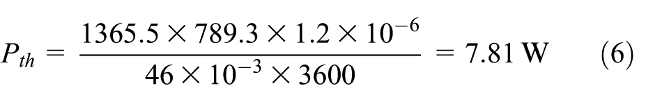
In the present experiment, the purity of ethanol is 99.7%. When the volume flow of liquid ethanol is 1.2 mL/h, the flame is stable, and its incomplete combustion rate is small, which is estimated as 5%. So, the actual burning thermal power of ethanol small-scale diffusion flame is

The external electric power can be calculated 43 as

According to VCC curve in the flame VCC, the calculated external electric powers are shown in Figure 14. The external electric powers all increased with the applied voltage under positive or negative electric field. The external electric power reached a maximum value of 5.704 × 10⁻³ W under positive electric field with the electrode spacing of 4 cm. The ratio of electric active power to actual burning thermal power of ethanol flame is defined as


Calculated electric power at the flow rate of 1.2 mL/h under different electric fields: (a) positive electric field and (b) negative electric field.
The ratios are all not greater than 0.077%, which means that the external electric power is very small compared with the actual burning thermal power of ethanol. Therefore, the impact of the Joule heat generated by electric field on the flame characteristics could be neglected. And it is proved that using the external DC electric field with very little power consumption to control combustion and flame in small scale is a feasible method.
Conclusion
The small-scale diffusion flames from a stainless steel tube using liquid ethanol as fuel under DC electric field were studied experimentally. The effects of a DC electric field on flame stability, flame temperature, flame shape, and flame VCC were investigated. The main conclusions are summarized as follows:
The stable working ranges of a small-scale combustor became narrower under the DC electric field. The main reason was that the evaporation velocity of liquid ethanol limited by great heat loss effect cannot keep up with the increasing of combustion velocity by the ionic wind effect;
The movements of those charged particles in flame enhanced the combustion process, resulting in higher flame temperatures under positive or negative DC electric field;
The flame heights decreased with increasing applied voltages, due to the ionic wind effect increasing the flame temperature and the diffusivity;
The VCC curves presented three distinct regions: the subsaturation region, the saturation region, and the supersaturation region;
The ratios of electric active power to actual burning thermal power of ethanol flame in this study were all less than 0.077%;
It can be inferred that using the external DC electric field with very little power consumption to control combustion and flame in small scale was a feasible method.
Future work by the authors shall include designing new combustor with low heat loss to achieve more broad stable combustion ranges. Numerical study on the effect of DC electric field on flame in small scale should be performed to analyze the mechanism quantitatively. A PID regulator and control system based on a simple flame model should be applied to actively control the combustion process.
Footnotes
Appendix 1
Academic Editor: Cheng-Xian Lin
Declaration of Conflicting Interests
The author(s) declared no potential conflicts of interest with respect to the research, authorship, and/or publication of this article.
Funding
The author(s) disclosed receipt of the following financial support for the research, authorship, and/or publication of this article: This work was supported by the National Natural Science Foundation of China (No. 51376066) and the Central Universities Fundamental Research Project in South China University of Technology (No. 201522083).