
Abstract
Improving the load-to-weight ratio of robots is an essential issue in the field of construction robots. In the present study, a method for analyzing the mobility of the typical multi-loop coupled mechanism is proposed, which combines the iterative replacement of generalized kinematic pairs with the screw theory. Then, the driving force/torque, driving power, and total power of actuators are considered as the evaluation indices, and the influence of different drive layouts on the mechanism is analyzed. Obtained results show that the driving force of the moving pair in the drive layout S1 or S3 changes smoothly compared with that in the drive layout S2, and the peak values of the driving force and the driving torque reduce by 49% and 12%, respectively. This demonstrates that the drive layout S1 effectively reduces the quality of the actuators. Finally, the coupled mechanism with the drive layout is applied in a high-altitude curtain wall installation robot, and the prototype of the robot is developed based on the coupled mechanism. Performed experiments show that the load-to-weight ratio in the proposed robot is about 13%.
Keywords
Introduction
Studies show that a multi-loop coupled mechanism has superior characteristics, including the compact structure and high stiffness. Moreover, from the perspective of mechanism mobility and drive layout selection, this mechanism has certain guiding significance to design construction robots with a high load-to-weight ratio.
Accordingly, performing the mobility analysis is one of the most essential issues in investigating the performance of multi-loop coupled mechanisms. Wang et al. 1 proposed a method to perform the mobility analysis based on the screw theory and the topology structure of mechanisms. Moreover. Liu et al. 2 proposed a procedure to determine the over-constraint for coupled mechanisms based on the screw theory. Then they proved the validity of the procedure by analyzing the constraint and mobility of the classical mechanism. Xie et al. 3 applied the line graph method and Grassmann line geometry and analyzed the mobility of a parallel robot. Ye et al. 4 analyzed the mobility of a 2PURR-PUR parallel manipulator through the screw theory and determined its motion characteristics. Furthermore, Guan et al. 5 analyzed the mobility of a 3-UPU manipulator with three translational degrees based on the screw theory. They considered three types of singularity and proposed a posture calculation method for each type. Sun et al. 6 applied the screw theory and accordingly, discussed the calculation method of the mobility for deployable structures of the scissor-like element (SLE). Guan et al. 7 proposed a new type of parallel manipulator and analyzed its mobility based on the screw theory. Li et al. 8 decomposed the magic ball by removing the kinematic sub-chains that do not affect the mobility of the mechanism. Then they applied the screw theory to calculate the mobility of the system. In order to investigate the mobility and kinematics of the Hoberman switch-pitch ball, Zhang et al. 9 applied the atlas method based on the constraint theory. Meanwhile, Wei et al. 10 applied the screw-loop equation to analyze the mobility and kinematic characteristics of the Hoberman switch-pitch ball. Bu et al. 11 proposed an innovative approach to deal with the mobility of the moving platform and the full-cycle mobility based on the intersection of screw spaces. Shen et al. 12 proposed a new parallel manipulator according to the topology design theory of the parallel mechanism (PM) based on the position and orientation characteristics (POC) equations. Then they calculated the main topological characteristics of the proposed mechanism such as POC, degree of freedom (DOF), and coupling degree. Li et al. 13 investigated the geometrical conditions and linear dependency of each branch screw system and then analyzed the parallel manipulators with low-mobility. However, further investigations show that for multi-loop coupled mechanisms, the constraint or motion provided by the coupling branch does not directly act on the moving platform. Therefore, when analyzing the mobility of a multi-loop coupled mechanism, it is necessary to make some special treatments or equivalent replacements for the coupling branch.
Studies showed that different drive layouts have a different impact on the kinematic and dynamic performance. In this regard, Gao et al. 14 evaluated the advantages and disadvantages of the drive layout from the perspective of dynamics. Based on Grassmann geometry, Geng et al. 15 analyzed the rationality of the mechanism drive selection. Zhao et al. 16 and Huang et al. 17 studied the rationality of the drive combination through a linear correlation of the screw system of the PM, thereby avoiding the complicated mathematical operations in the drive selection discrimination. Bu 18 analyzed the influence of different drive layouts on the actuated stiffness and structural stiffness of the mechanism and found the optimal selection of a drive layout of actuators. Li et al. 19 analyzed the characteristics of tricept mechanisms under different actuator positions based on the distribution characteristics of the motion flexibility, maximum, and minimum stiffness indices in the mid-section of the mechanism position space. Reviewing the literature indicates that only a few evaluations have been conducted so far on the driving force/torque, driving power, and total power of the mechanism.
Based on the conducted literature survey, it is intended to map the original coupled mechanism to a simple PM. In this regard, the generalized kinematic pair replacement method and the modified Grübler-Kutzbach equation are applied to solve the mobility of a typical multi-loop coupled mechanism. Then the drive layout is optimized through numerical methods from different aspects, including the driving force/torque, driving power, and total power. Finally, the coupled mechanism with the optimal drive layout will be applied to a high-altitude curtain wall installation robot to complete the prototype development.
Decoupling analysis of the multi-loop coupled mechanism
Figure 1 shows a schematic diagram of the multi-loop coupled mechanism composed of 11 connecting rods (L1∼L11), 10 rotating pairs (R1∼R7 and

Schematic diagram of the multi-loop coupled mechanism.
It is observed that the PM R1R2P1R3R4 and the parallelogram mechanism
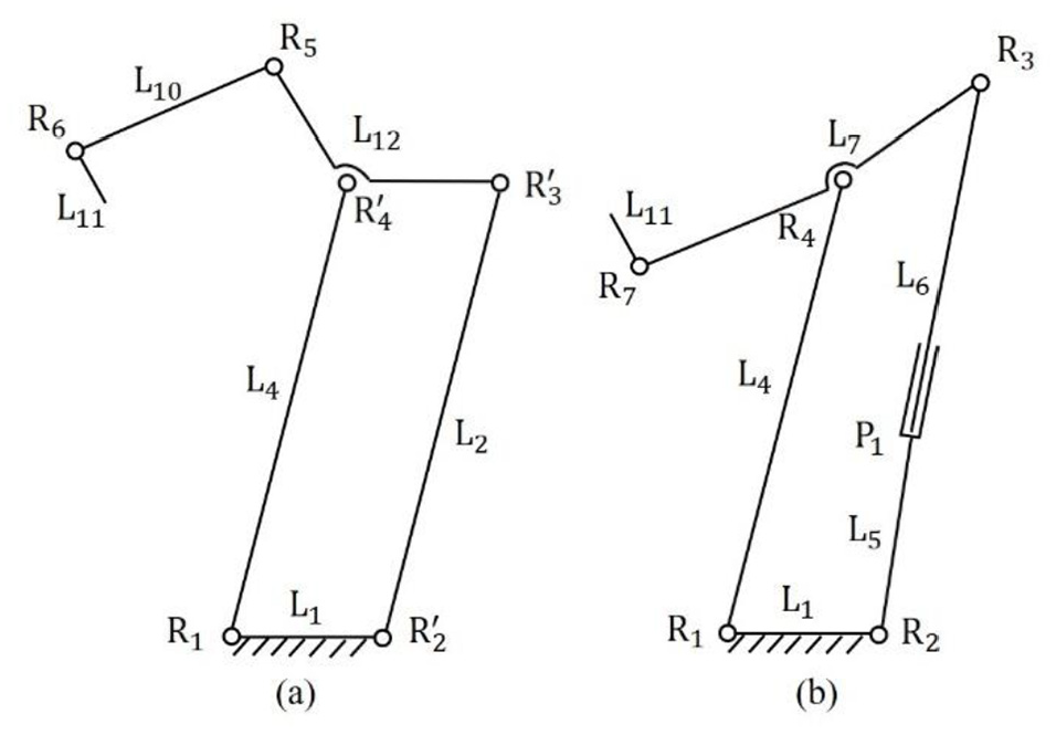
Equivalent branch of the multi-loop coupled mechanism: (a) branch Q1 and (b) branch Q2.
Mobility analysis
For the two equivalent branches, the component at the coupling node is considered as the first output component to analyze the motion characteristics of the output component relative to the frame. In each equivalent branch, the mechanism connecting the frame and the coupling node is equivalent to a generalized kinematic pair. The generalized kinematic pair and the kinematic pair after the coupling node forms an independent series chain. Therefore, the whole multi-loop coupled mechanism is equivalent to a PM with two independent series chains.
Figure 3 illustrates the parallelogram mechanism of Q1 branch composed of four rotating pairs.

Parallelogram mechanism in Q1 branch.
This parallelogram mechanism can be regarded as a PM with two sub-branches. A1 and X1 axes are the origin coordinate and the axis along the direction of rod A1B1, respectively. Moreover, Y1 and Z1 axes are located in the plane of the parallelogram and along the direction of the rotation pair axis, respectively. For the first sub-branch of the parallelogram, the kinematic screw system includes two screws:
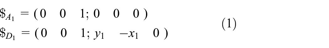
Where, (x1, y1, 0) is the coordinate of point D1, and the constraint screw system of the first sub-branch can be expressed in the form below:

Moreover, the kinematic system of the second sub-branch is as the following:

Where, l1 represents the length of the connecting rod A1B1. Moreover, the constraint screw system of the second sub-branch is:

Combining equations (2) and (4), the constraint screw system of the whole parallelogram mechanism is obtained as follows:

In order to calculate the inverse constraint screw of the abovementioned equation, the following equation is used:

Therefore, the connecting rod C1D1 is allowed to move in the plane A1B1C1D1, and this parallelogram mechanism is equivalent to a generalized moving pair.
According to the abovementioned analysis, the Q1 branch of this coupled mechanism is equivalent to an open chain with three kinematic pairs, including one generalized moving pair connected to the frame and two rotating pairs.
The detailed analysis process of the Q2 branch is as follows: the PM composed of four rotating pairs and one moving pair as shown in Figure 4 is analyzed.

Parallel mechanism in Q2 branch.
Q2 branch can be regarded as a PM with two sub-branches. A is selected as the origin coordinate. Moreover, X2, Y2, and Z2 axes are along the direction of connecting rod AB, in the plane of the PM and along the direction of the rotation pair axis, respectively. The kinematic screw system for the first sub-branch of the PM includes two screws as the following:
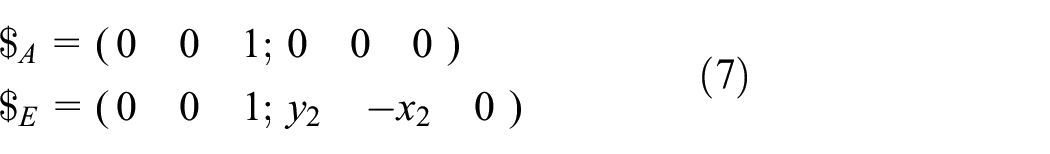
Where, (x2, y2, 0) is the coordinate of point E, and the constraint screw system of the first sub-branch is:

The kinematic screw system of the second sub-branch is:
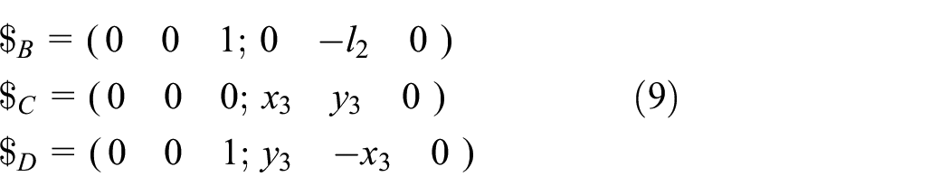
Where, l2 and (x3, y3, 0) represent the length of the connecting rod AB and the coordinate of point D, respectively. Moreover, the constraint screw system of the second sub-branch is:

Combining equations (8) and (10), the constraint screw system of the PM is mathematically expressed as follows:

In order to calculate the inverse constraint screw of the above formula, the following equations are required:

It means that the connecting rod DE is allowed to move and rotate around the Z2 axis in the plane of the PM, and the PM is equivalent to one generalized moving pair and one generalized rotating pair.
According to the abovementioned analysis, the Q2 branch of this coupled mechanism is equivalent to an open chain with three kinematic pairs: one generalized moving pair connected to the frame, one generalized rotating pair, and one rotating pair.
Therefore, Figure 5 illustrates that the multi-loop coupled mechanism is equivalent to one PM composed of two series chains. The parallelogram mechanism in the Q1 branch is replaced by the generalized moving pair P2. Moreover, the PM in the Q2 branch is replaced by the generalized moving pair P3 and the generalized rotating pair R8.
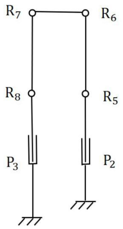
Equivalent parallel mechanism of the multi-loop coupled mechanism.
By applying the modified Grübler-Kutzbach equation, the degree of freedom (DOF) of the end member of the mechanism is obtained as follows:

The two branches provide a constraint force along the Z-axis and a constraint couple along the Y-axis. Therefore, there are two common constraints, named
No matter how the mechanism operates, a coordinate system as shown in Figures 3 and 4 is established. In this coordinate system, the geometric correlation between the kinematic pairs of each branch chain remains unchanged. In other words, their kinematic screw and constraint screw remain unchanged. Therefore, the obtained DOF of the mechanism is that of the full-circle.
Rationality analysis of the drive selection and optimization of the drive layout
Rationality analysis of the drive selection
According to the abovementioned analysis, the multi-loop coupled mechanism shown in Figure 1 has two DOFs. It is necessary to add two independent drives to the mechanism to make it have a definite movement. The selection of mechanism driving joints generally follows two principles: (1) In order to obtain a higher driving force/torque, the driving joint should be a moving pair if possible. (2) In order to stabilize the movement of the mechanism, the driving joint should select the moving pair connected to the frame if possible. Therefore, Table 1 lists that there are three kinds of drive layouts for the initial selection of the multi-loop coupled mechanism based on the above principles.
Drive layouts of the multi-loop coupled mechanism.
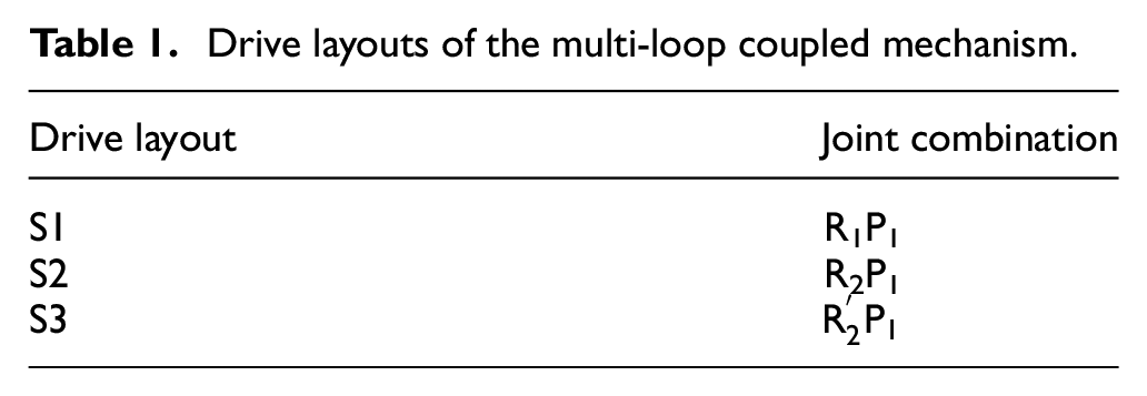
The joint R1P1 is selected as the driving pair. After rigidity, the PMs in branches Q1 and Q2 are all converted into stable triangular mechanisms. Therefore, the connecting rod L7 and L9 can be regarded as the frame and form a stable triangular mechanism with the connecting rods L10 and L11. As a result, the novel mechanism obtained after the rigidity of the driving joint does not have DOF. Meanwhile, it is proved that the other two drive layouts are reasonable. 20
Optimization of the drive layout
Different drive layouts will have a great impact on the dynamic performance of the above multi-loop coupled mechanism. Therefore, this section takes driving force/torque, driving power and total power of actuators as evaluation indices to optimize and analyze the drive layout.
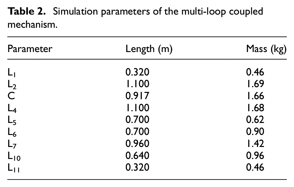
The three-dimensional model of the multi-loop coupled mechanism is established by SolidWorks and imported into Adams software for simulation. It is assumed that the material is steel. The density, Young’s modulus and Poisson’s ratio of the material are 7.801E+03 kg/m3, 2.07E+11 N/m2 and 0.29, respectively. Moreover, the cross-section of the connecting rod is 0.01 × 0.02 m, and the circumference of
Simulation parameters of the multi-loop coupled mechanism.
It is assumed that the lower endpoint of the rod L11 is the reference point of the moving platform. Moreover, the simulation time and the simulation steps are 10 s and 100, respectively. Figure 6 shows the motion trajectory of the reference point of the moving platform in the XY plane.
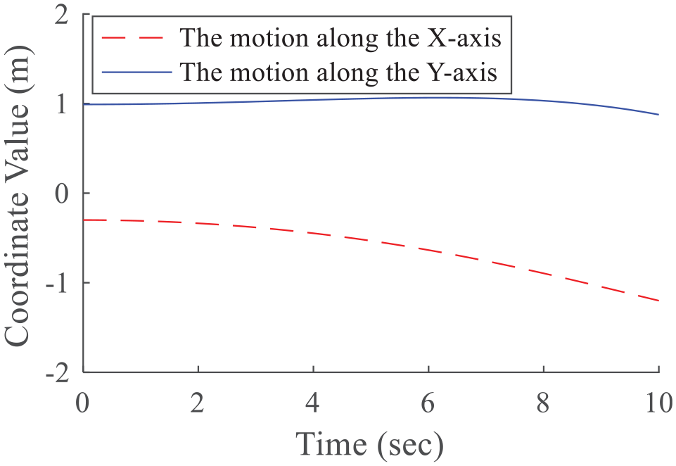
Motion trajectory of the reference point of the moving platform in XY plane.
The angular velocity of the rotating pair R1, R2,
Figure 7 shows the variation of instantaneous driving torque and instantaneous driving force of the multi-loop coupled mechanism with time in three drive layouts.

Changes of driving force/torque in three different drive layouts.
In Figure 7,
The driving power of the multi-loop coupled mechanism in different drive layouts is as follows:

Where,

Changes of the angular velocity of the rotating pair and moving speed of the moving pair in three different drive layouts.
Figure 9 illustrates the variation of the driving power of the actuators in different drive layouts for the mechanism obtained by equation (14).

Driving power changes in different drive layouts.
Figure 9 shows that when the mechanism completes the same movement process in the drive layout S1 or S3, the driving powers in S1 and S3 are the same, and are lower than that in S2 within 0∼6.3 s and slightly higher than that in S2 within 6.3∼10 s. However, the overall difference is not significant.
The total power of the multi-loop coupled mechanism in different drive layouts is mathematically expressed as follows:
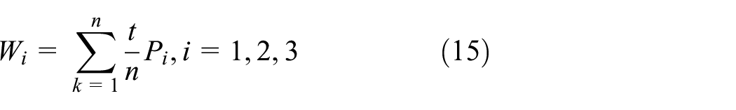
In equation (15), Wi (i = 1, 2, 3), t and n represent the total power in three drive layouts, the simulation time and simulation steps, respectively. It is assumed that t = 10, n = 100. Table 3 shows the total power of the multi-loop coupled mechanism in different drive layouts according to equation (15).
Total power.

Table 3 shows that the total power is equal for the mechanism to complete the same motion in the drive layout S1 or S3 and slightly smaller than that of the drive layout S2.
In summary, the driving power and total power in the drive layout S1 or S3 are the same and do not have a significant difference compared with that in the drive layout S2 when the mechanism completes the same motion process. Moreover, the driving force of the moving pair in S1 or S3 is stable and the peak value is reduced by 49% and the driving torque peak value of the rotating pair is reduced by 12%. Therefore, the drive layouts S1 and S3 are better than the drive layout S2. In other words, the joint R1P1 or
Application and prototype development
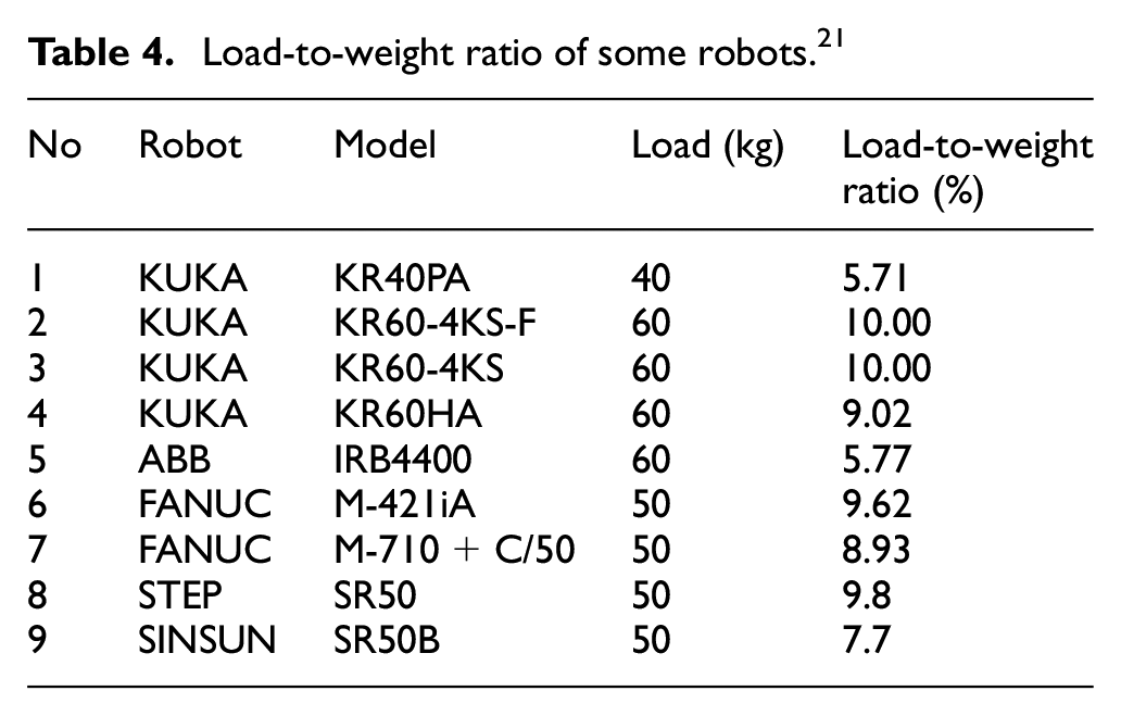
The load-to-weight ratio refers to the ratio of a robot’s load to its own weight. Table 4 lists the load-to-weight ratio of some robots with a load of about 50 kg. It is worth noting that the h the higher the ratio, the greater the robot’s load capacity under the same weight. Since the operation object of a high-altitude curtain wall installation robot is a glass curtain wall and other heavy building components, it should obtain higher load capacity compared with conventional industrial robots. Meanwhile, the robot body should have lighter weight because it needs to be installed on the high-altitude platform. The multi-loop coupled mechanism has the characteristics of compact structure and high rigidity. Therefore, the multi-loop coupled mechanism proposed in this study is used as the main structure of the high-altitude curtain wall installation robot for the prototype development.
Load-to-weight ratio of some robots. 21
Based on the abovementioned analysis, it is found that by selecting the joint R1P1 or

A prototype of the high-altitude curtain wall installation robot.
The load-to-weight ratio of the high-altitude curtain wall installation robot is:

In equation (16), mmax and M represent the maximum load of the robot and the weight of the robot body, respectively. The experimental results show that mmax = 59.6 kg and M = 452 kg. According to equation (16), the load-to-weight ratio of the high-altitude curtain wall installation robot developed in this study is about 13%.
Conclusion
In the present study, the mobility of a multi-loop coupled mechanism and its drive layout are investigated. The main conclusions are as follows:
A method for analyzing the mobility of a typical multi-loop coupled mechanism is proposed, which combines the iterative replacement of generalized kinematic pairs with screw theory, and provides a novel idea for analyzing the mobility of multi-loop coupled mechanisms.
The multi-loop coupled mechanism is divided into two branches Q1 and Q2 to complete the decoupling analysis of the mechanism. Then, based on the screw theory, the complex multi-loop coupled mechanism is equivalent to a simple PM. Using the modified Grübler-Kutzbach equation, the DOF of the original multi-loop coupled mechanism is obtained.
There are three reasonable drive layouts, including S1, S2, and S3. The effects of the three different drive layouts on the driving force/torque, driving power and total power during the same movement are analyzed through simulation. The simulation result shows that the driving force of the moving pair in the drive layout S1 or S3 is stable, and the peak value of the driving force and the driving torque are reduced by 49% and 12%, respectively. Therefore, either the joint R1P1 in S1 or
The multi-loop coupled mechanism is applied to a high-altitude curtain wall installation robot. The joint R1P1 in S1 is selected as the driving pair, and a prototype of the robot is manufactured. The load-to-weight ratio is about 13%.
The mobility analysis and the drive layout optimization method adopted in this study provides an idea for the analysis of other multi-loop coupled mechanisms and the improvement of the robot’s load-to-weight ratio, which has a positive role in promoting the application of the multi-loop coupled mechanisms and the development of the construction robot.
Footnotes
Handling Editor: James Baldwin
Declaration of conflicting interests
The author(s) declared no potential conflicts of interest with respect to the research, authorship, and/or publication of this article.
Funding
The author(s) disclosed receipt of the following financial support for the research, authorship, and/or publication of this article: This work was supported by the National Key R&D Program of China (2018YFB1306900), the National Natural Science Foundation of China (U1813222) and the Natural Science Foundation of Hebei Province (E2019202338).
Data Availability
The underlying research materials related to this paper are available from the corresponding author.