
Abstract
Abstract A novel asymmetrical spatial parallel manipulator with three degrees of freedom is proposed. The moving platform of the manipulator has two-translational and one-rotational (2T1R) DOFs with respect to the fixed base. Two other manipulators with platforms with high rotational ability are obtained by making simple changes to the original manipulator's architecture. The platform of the new mechanisms can rotate 360 degrees around their axis. The motion output characteristics and the mobility of the manipulator are analyzed based on the screw theory. Solutions for position and pose, velocity, acceleration are derived. The Jacobian matrix, mapping the input velocity vector space into the output velocity vector space, is an identical matrix, so the parallel mechanism is free-singularity and fully-isotropic. Therefore, these manipulators perform very well with regard to motion and force transmission and have potential applications in the field of industrial robots and medical devices.
1. Introduction
A parallel manipulator is a closed-loop mechanism, which generally consists of a moving platform connected to a fixed base by several serial kinematic chains (or limbs) in parallel. The number of limbs is usually equal to the number of degrees of freedom of the moving platform such that each limb is driven by no more than one actuator and all the actuators can be installed on or near the fixed base. Compared with the traditional serial mechanisms, parallel manipulators have many merits, such as high stiffness, large load carrying capacity, high accuracy, high velocity and low accumulation of positional errors. Therefore, parallel manipulators have widely potential applications in the fields of industrial robots, flight simulators, parallel machine tools, medical devices, radar antennas, telescopes and so on. In the past three decades, many novel parallel manipulators were designed and applied in industry, for example, Delta robot [1], Orthoglide manipulator [2], Agile Eye mechanism [3], H4 robot[4], and Quadrupteron mechanism [5]. More and more international scholars have devoted themselves to the study of parallel manipulators [6–10].
However, parallel manipulators also have some drawbacks, such as a limited workspace, more constraining singularity loci or a high coupling of kinematics and dynamics. Kinematic coupling is one of the inherent characteristics of parallel manipulators in general. On the one hand, it is helpful in enhancing the rigidity and loading capability of the manipulator, which contributes to the parallel manipulators' applications in the field, such as for numerical control parallel machine tools and flight simulators, where a high loading capability is needed. On the other hand, the strong coupling has actually increased the difficult problems in the kinematic analysis and the control design. Although decoupled parallel manipulators are possibly inferior to general parallel manipulators in rigidity and loading capability, they are very simple in their kinematic solutions and motion controllability design. Therefore, the decoupled parallel robotic manipulators have a broad application prospect in medical mechanisms and micro-operation robots.
Recently, partially coupled, decoupled, uncoupled and even fully-isotropic parallel manipulators have received more and more attention from scholars in the fields of mechanisms and robotics. Richard, et al. [5] performed a kinematics analysis of a partially decoupled 4-DOF 3T1R parallel manipulator. Briot, et al. [11] presented a family of partially decoupled parallel manipulators called PAMINSA. Kim and Tsai [12] put forward a 3-PRRR uncoupled purely translational parallel manipulator with three limbs in an orthogonal arrangement. Li, et al. [13] presented an uncoupled translational parallel manipulator, named R-CUBE, which was composed only of revolute joints. Zhang, et al. [14] presented a 3-CRC translational parallel manipulator. When the linear inputs were adopted, the Jacobian matrix was identical and the manipulator showed itself to be fully-isotropic throughout the entire workspace. Carricato [15] performed type synthesis of fully-isotropic 4-DOF parallel manipulators for Shoenflies motion by using the screw theory. Gogu [16–17] put forward the linear transformation theory to realize structural synthesis of free-singularity fully-isotropic parallel manipulators.
A novel 3-DOF asymmetrical fully-isotropic parallel manipulator with a high rotational ability is proposed in this paper. The moving platform has two-translational and one-rotational DOFs with respect to the base. Two other manipulators are obtained by making simple changes to the original mechanism's structure. An analysis of the motion output characteristics and kinematic problems of the manipulator are performed.
2. Structure Design
The architecture of the original parallel manipulator, IsoS2T1R-I, is illustrated in Figure 1. It consists of a moving platform connected to a fixed base by three different limbs. The first limb is composed of one cylindrical pair and three revolute joints. The axes of the cylindrical pair and the first two revolute joints are parallel to each other and perpendicular to the third revolute joint, so the structure of the first limb can be described as C1 //R2 //R3 ⊥ R4. The second is made up of two prismatic pairs, P5 and P6, and one revolute joint, R7. The axes of the two prismatic pairs are normal to each other and the axes of joints P1 and R3 are parallel, as P5(⊥ P6 ⊥) / /R7. The third consists of one revolute, one prismatic and two universal joints. The sequence of these joints from the base to the platform is R8 – U9 – P10 – U11, where P, R, C and U denote the prismatic, revolute, cylindrical and universal joints, respectively.
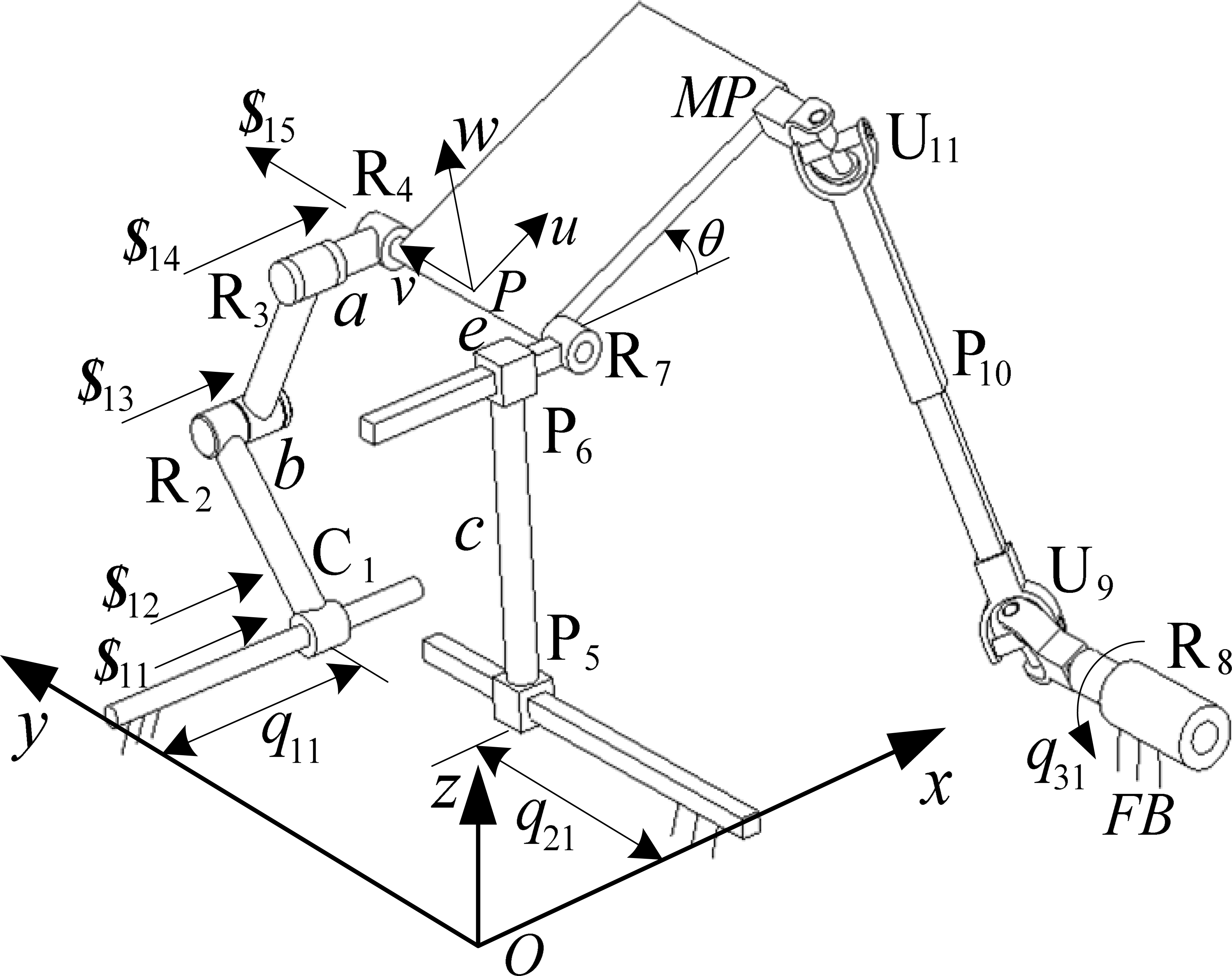
The novel IsoS2T1R-I parallel manipulator
In order to gain the expected output motion characteristics, the following assembly conditions should be kept to:
The axes of joints, C1 and P5, connected with the fixed base, are perpendicular to each other. The axis of joint R8 mounted in the base is parallel to joint P5 and it can be involved in the same plane determined by joints C1 and P5 or not. Joints, R4, R7 and U11, are attached to the moving platform. At the same time, the axes of R4 and R7 are collinear and not parallel to one of the axes of U11 joint connected directly to the platform. For the purpose of simplifying the structure of the manipulator, we assume the axis of U11 joint next to the platform is normal to the axis of R7 joint. The axes of U9 and U11 connected to P10 or connected to the platform and the axis of R7 are parallel to each other, respectively.
In addition, three joints, C1, P5 and R8, attached to the base, are chosen as the actuated joints. As far as the C1 pair is concerned, its linear translation degree of freedom is selected as the actuated input of the first limb.
A double-colour topological diagram of the IsoS2T1R-I manipulator is shown in Figure 2, where the white dots “ˆ” and the black dots “□” denote the joints and the links of the manipulator, respectively. If we want to present one joint connected with a link, it can be described by a curve which joins a corresponding white dot and a black dot. The structural form of the manipulator reveals that obviously there are three limbs connecting the base with the platform.
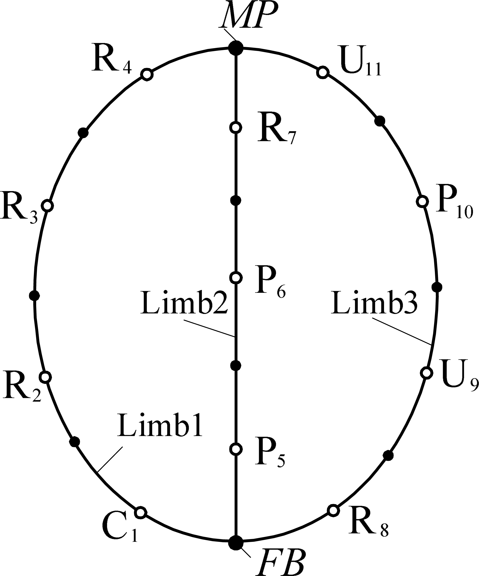
Topological diagram of IsoS2T1R-I manipulator
As mentioned above, parallel manipulators also have disadvantages, such as a complicated structure and a small workspace. The architecture of the IsoS2T1R-I manipulator will be evolved as follows so that some abilities will be promoted.
Firstly, the platform of the IsoS2T1R-I manipulator is degenerated into an end-effector (EE). Then the axes of R4 joint in the first limb and R7 joint in the second limb must remain collinear and connect with EE. Joint U11 is attached to another end of EE and its one rotational axis adjoining to the platform is still perpendicular to the axis of R7 joint. Finally, the assembly sequence of the three limbs of the new manipulator is adjusted so as to achieve a more reasonable architecture and the new manipulator is called IsoS2T1R-II, as shown in Figure 3. However, its topological structure remains unchanged and is consistent with Figure 2.

IsoS2T1R-II parallel manipulator
From Figure 3, we know that there is no relative motion between revolute joints R4 and R7, so these two joints can be combined into one revolute joint R12 without requiring any further change to the assembly conditions. Then the IsoS2T1R-II manipulator is evolved into a new one, called IsoS2T1R-III, see Figure 4. The double-colour topological diagram of the IsoS2T1R-III manipulator is shown in Figure 5. It is obvious that there are only two limbs connected to the EE of the IsoS2T1R-III manipulator. The first limb is a hybrid kinematic chain including a closed loop, which is composed of joints, C1, R2, R3, P6 and P5, and a revolute joint R12. Another limb is identical to the third limb of the IsoS2T1R-I manipulator. Therefore, the structure of the IsoS2T1R-III manipulator is different from the two others.

IsoS2T1R-III parallel manipulator

Topological diagram of IsoS2T1R-III
Compared with the IsoS2T1R-I manipulator, the architectures of the IsoS2T1R-II and IsoS2T1R-III manipulators are simpler and more compact. Moreover, the assembly configurations of the later two manipulators are more reasonable, which helps to effectively avoid interference between the different limbs. It is more important that the rotational ability of the platforms of the evolved mechanisms is greatly improved. They can perform a complete rotation around their axes if the structural sizes are available. However, for general parallel manipulators, the rotational ability of the platforms is less than 180 degrees. So the rotational ability of the parallel manipulators proposed here is greater than those in the literature [18–19]. Although there are differences in structures for these parallel manipulators, their kinematic characteristics are completely identical. We only need to take one of the manipulators as an example to analyze their kinematics.
3. Theoretical Base of the Screw Theory
The screw theory is an effective mathematic tool in the kinematics analysis [19–20] and structure synthesis [21–23] of parallel manipulators. Several basic concepts in screw theory will be briefly reviewed in the following.
3.1 Unit Screw
A unit screw is defined by a straight line with an associated pitch as follows

where

which is a line vector. It can be used to represent the kinematic screw of a revolute joint and
In addition, if the pitch of a screw is infinite, the unit screw in Eq.(1) will be defined as

which is a couple vector and can be used for a kinematic screw of a prismatic pair,
A unit screw can also be represented by a Plücker coordinate with six scalar components as follows
where the first three components are the direction cosine of the screw axis, the second three are the dual part of the first three.
A screw system is a vector space composed of a group of linearly independent screws,
3.2 Reciprocal Screws
Two screws,


where “○” denotes the reciprocal product of the screws,
Physically speaking, if the reciprocal product of two screws is equal to zero, one of them represents the motion of the rigid body, the other is constraint force exerted on the body. The reciprocal product of screws can be defined as the instantaneous virtual power developed by a force screw along the kinematic screw. Therefore, a reciprocal screw
3.3 Actuation Screw
An actuation screw is defined as a screw which is reciprocal to all the kinematic screws of the other joints with the exception of the actuated screw within the identical limb. The actuated screw is a kinematic screw associated with the actuated joint of the given limb. Physically speaking, the actuation screw is a force screw exerted on the platform of the manipulator by the actuated joint. In other words, the actuation screw is an actuated force exerted on the platform by the actuated joint.
For a given kinematic chain, the steps to solve its actuation screw could be described as follows
Work out the kinematic screw system Derive the constraint screw system Determine the constraint screw system The different part between system
Then we know that
4. Mobility Analysis
Without loss of generality, we take the IsoS2T1R-I parallel manipulator, see Figure 1, as an example to analyze its mobility and kinematics. A fixed reference frame O-xyz is attached to the base, the original point O is located in the plane determined by joints C1 and P5, the x-axis is parallel to the direction of C1 joint, the y-axis is parallel to the axis of P5 joint, the z-axis is defined by the right-hand rule.
Screw theory is a popular and convenient method used to analyze the mobility of parallel mechanisms [24]. Based on the screw theory, the Kinematic screw system, or so-called twist system, of the first limb in the fixed frame, O-xyz, can be described as follows

where
From Eq.(7) we know that the kinematic screw system of the first limb is a 5-system and its constraint screw system, or so-called wrench system, must be a 1-system. In terms of the reciprocal principle, we have

which shows that the constraint screw
Similarly, the constraint screw system of the second limb can be derived as

These three constraint screws represent an infinite pitch screw along the x-axis, an infinite pitch screw along the z-axis and a zero-pitch screw whose axis is parallel to the z-axis, respectively. Therefore, the constraint screws of the second limb restrict the rotational DOFs around the x- and z-axes and the translational DOF along the z-axis.
As for the third limb, R8 – U9 – P10 – U11, it cannot provide any constraints to the platform since its connectivity is equal to 6. Therefore, the first two limbs together restrict the rotational DOFs around the x- and z-axes and the translational DOF along the z-axis of the platform. In other words, the platform of the manipulator can only rotate around the y-axis and translate along the x- and z-axes. From Eqs. (8) and (9), we know that there is one common constraint screw between the constraint screw system of the first limb and the constraint screw system of the second limb. Thus the parallel manipulators proposed here are over-constrained mechanisms with three-DOFs and the over-constraint number is 1.
In order to calculate the amount of mobility of the over-constrained parallel manipulators, a modified form of Kutzbach-Grübler formula was proposed in [25]:

where F is the effective DOF of the manipulator, d denotes the order of the mechanism, for the planar and spherical mechanisms d = 3, the spatial mechanisms d = 6, n is the number of links (including the platform and the base), g is the number of joints and joint i (1≤i≤g) has connectivity fi, v is the over-constraint number of the mechanism, ζ is the number of the local DOF.
For the parallel manipulator shown in Fig.1, n = 10, g = 11, d = 6, Σ fi = 14, v = 1, ζ = 0, substituting all these parameters into Eq.(10), we get F = 3. This result is fully consistent with the motion output characteristics of the moving platform.
5. Kinematic Analysis
The kinematics problems of the manipulators include position and pose analysis, velocity analysis and acceleration analysis. Generally, the sequence of kinematics analysis is to firstly derive the position and pose equations based on the different methods, then to develop the velocity and acceleration equations by differentiating the position and pose equations with respect to time in one and two orders, respectively. However, in some special cases, it is hard to figure out the position or pose equations directly according to the structural conditions of the mechanisms. The reciprocal screw theory method is applied to resolve this problem.
Another reference frame P – uvw, also called the moving frame, is fixed to the platform. The original point P is located on the axis of R4 (or R7) joint. The v-axis is aligned with the axis of R4 joint, the u-axis is perpendicular to the v-axis and in the platform; similarly, the w-axis also satisfies the right-hand rule, referring to Fig.1. a is the displacement of R4 joint with respect to R3. b is the offset of link R2R3 with respect to link C1R2, c is the offset of P6 pair with respect to P5. e is the distance between point P and R7 joint along its axis. θ represents the pose angle of the platform around the y-axis. qi1 denotes the actuated joint's input displacement of the ith limb.
Supposedly, the position coordinate of point P in the fixed frame is (x,y,z), according to the assembly configurations of the first limb, one of the position equations can be directly calculated as follows

Similarly, another position equation is derived based on the assembly conditions of the second limb

Furthermore, the third position parameter of the point P can be obtained based on the structural conditions of the manipulator, referring to Fig. 1, and

From Eqs. (11) and (12), we can see that the position coordinates x and y of point P only relate to the actuated inputs q11 of the first limb and q21 of the second limb, respectively. However, both of them have nothing to do with the actuated q31 of the third limb.
Differentiating Eqs. (11) and (12) with respect to time, yields


For the pose angle θ of the platform, it is difficult to directly define its function expression for three actuated inputs qi1 based on the assembly conditions of the mechanism. However, if the expression of the angular velocity ωy of the platform is obtained first, then the pose angle can be calculated by use of the integration method.
We know that the instantaneous velocities of the mobile platform can be described through the twists of the kinematic chains of the parallel manipulator and

where
Taking the reciprocal product of both sides of Eq.(16) with respect to the actuation screw

where
The independent structure of the third limb is shown in Figure 6. In order to describe the kinematic screw of each joint conveniently, a sub-coordinate system O1 – x1y1z1 is set up, its original point O1 coincides with the universal joint U9 and the three axes are parallel to the axes of the fixed frame O – xyz, respectively. Here the universal joint can be seen to be two revolute joints with perpendicular and intersecting axes. q31, q32 and q33 are the rotary angles of the corresponding joints around their own axes. Then the twist system of the third limb in the O1 – x1y1z1 frame can be expressed

Diagram of the third limb

where c and s represent cos(·) and sin(·), respectively.
L34 = cq31cq33 + sq31sq32sq33, M34 = cq32sq33,
N34 = –sq31cq33 + cq31sq32sq33.
When the actuated screw,

It is obvious that
For the IsoS2T1R-I manipulator, the velocity vector of the original point P of the moving frame is

Substituting Eqs. (19), (20) and the actuated screw

When the manipulator is in the general position, cosq32 ≠ 0, thus Eq. (21) can be rearranged as follows

which is the third velocity formula. Based on Eq. (22), we know that the rotary output, ωy, of the moving platform is only related to the input velocity, q̇31, of the actuated joint R8.
Integrating Eq. (22) one time, we obtain

where θ is the pose angle of the platform, q31 is the input angle of the actuated joint R8, θ0 is an integral constant and its value is dependent on the original pose angle of the platform. If the initial assembly configuration of the platform is parallel to the plane O – xy, then we have θ0 = 0 and Eq. (23) can be rewritten as

Here, three forward position equations and three forward velocity equations of the manipulator have been derived. The inverse kinematic formulas can also be conveniently computed by Eqs. (11), (12), (24), (14), (15) and (23). Based on the kinematic analysis we know that there exists a one-to-one corresponding controlling relationship between one of the input velocities of the actuated joints and one of the output velocities of the platform. Therefore, this manipulator is an uncoupled mechanism.
Rearranging Eqs. (15), (15) and (23) into a matrix form, yields

Evidently, the kinematic Jacobian matrix of the manipulator is an identity 3×3 matrix, so the acceleration equations can be obtained by differentiating Eq. (25) with respect to time
Similar to velocity, there also exists a one-to-one corresponding control relationship between the output linear or angular acceleration of the platform and the input acceleration of the actuated joints. So this makes it very easy for the control design of the manipulator.
From Eq.(26), we know that the Jacobian is an identity matrix, thus the condition number is always equal to 1 throughout the entire workspace. So this manipulator is a free-singularity fully-isotropic parallel mechanism.
6. Conclusions
A new family of asymmetrical spatial parallel manipulators with two translational and one rotary degree of freedom are presented in this paper. The output characteristic of the moving platform is analyzed based on the screw theory. Mobility analysis and kinematic problems of the mechanism have been discussed. In terms of the velocity equation we know that the Jacobian of the parallel manipulator is a 3×3 identity matrix, there exists no singular configuration within the whole workspace. Moreover, the condition number of the Jacobian is always equal to one, so this manipulator is a free-singularity and is fully isotropic and performs well with regard to its force and motion transmission capabilities. It is more important that the platforms of these manipulators possess a higher rotational ability than general parallel manipulators which have been designed. The manipulators proposed here can rotate 360 degrees around the y-axis.
7. Acknowledgments
This work was supported by National Natural Science Foundation of China under grant 50905055, Natural Science Foundation of Education Department of Henan Province under grant 2010A460006, Young-Backbone Teacher Foundation Higher Schools of Henan Province under grant 2010GGJS-079 and Doctoral Research Foundation of Henan University of Science and Technology.