
Abstract
The paper deals with the influence of the thermal state of the machine on its function and product accuracy. The results of the experimental measurement on a particular machine are presented and consequently a virtual simulation of the thermal state of the working space depending on the time of its operation of the machine is performed. Model examples for changed boundary conditions are calculated with respect to the possibility of reducing energy consumption while maintaining a constant thermal state of the machine. Based on the simulation of the thermal state a structural analysis is performed to determine the effect of thermal conditions on the clearance of the ram guiding.
Introduction
Forming technology is currently one of the most productive production methods. It can be assumed that approximately 80% of the products are involved in forming technology in some way. They are both types of forging hot and cold forming. An even greater increase in the number of products produced by forming will occur as soon as this technology meets other high requirements for product quality and precision. Therefore, more and more emphasis is placed on producing such forming machinery that can eliminate technological inaccuracies in hot forming and thus guarantee high quality and accuracy of products (as is achieved in machining operations). Forming machine designers try to improve their accuracy, for example by eliminating clearance in their guidance, balancing moving masses, increasing machine rigidity, eliminating dynamic effects, and more.1,2
Until now, almost no attention has been paid to the thermal condition of the forming machine, since it was almost negligible compared to the other mentioned effects. With increasing demands on accuracy, the influence of thermal load on machine behavior is beginning to become of considerable importance, regardless of the type of technology produced on the machine.3–6
Thermal expansion of the functional parts of the machine is directly translated into product precision, decreasing or increasing clearance in the bearing and in the guide. 7 It can also affect machine life. It also contributes directly to the machine’s energy balance.8,9
There are researches dealing with thermal influence of cutting operation made by machine tools. It is known that heat influences machine precision. Known thermal load can be directly inserted into the machine tools operating system and compensate an error by this way.10,11
Therefore, it is very current to deal with the thermal balance of the forming machine’s operation and the influence of the thermal condition of the machine on its operation, in order to prevent the consequences of thermal changes in the machine for its operation.
Sources of thermal stressing of the machine
Sources of the thermal load of the machine are (Figure 1):
Thermal load of the machine from technologic process
Thermal load of the machine while working itself

Photo (left) and thermal cam photo picture of forging machine while working (right) (on upper picture is part of press drive, on lower picture is technologic process).
The issue of research of the influence of technology thermal balance and the influence of the thermal state of operating machine is very broad topic. This article deals with heat load from the technological process only.
Thermal load of the machine from technological process
General description of heat load from technological process
During the technological hot forming process of steel temperature reaches high values. The temperature of the formed piece is usually in the range of 1100–1200°C, see the following diagram (Figure 2).

Forming temperatures while hot in diagram iron – carbon.
It is therefore necessary to identify areas where the maximum influence (thermal expansion) of the basic parts of the forming machine occurs and to analyse their influence on the construction and thus on the required accuracy of the machine.
Thermally loaded machine parts are (Figure 3):
Ram with tool
Press columns
Press table with lower tool
Ram guiding

Image of thermally affected area of forging press (left) and view into working space of press while preheated forging with temperature of 1150°C is inside upsetting die (right).
Measurement of the thermal state of the machine during forging
The thermal influence of hot forging on a forging press with a nominal force of 65 MN was measured. This measurement serves as a standard for setting up boundary conditions in virtual modeling of thermal conditions of the machine. The measurement was carried out with the FLIR thermal cam (Figure 4). Because of emissivity issue (machine emissivity is unknown), comparison of thermo cam results was done with use of contact thermometer.

Timetable of the forgings inside working place of the press.
Before the forging operations, dies were preheated for 12 h with a gas burner to the target value 200°C. With regard to the characteristics of the burner, we assume that most of the thermal energy has transferred to the upper tool.
There was a 30-min break between preheating and the forging itself to stabilize the temperatures between the tools and their holders.
Forged forging dimensions are 130 mm diameter and 310 mm length and weight about 30 kg. Forgings are heated by induction furnace to forging temperature of 1150°C. Those forgings size and type corresponds to an appropriate range for this press.
Forging took place in three forging operations:
upsetting
preforming
sizing
Forging time of the press was about 24 s, including all three human operated operations. The feed rate of the semi products from the induction furnace was 100 s, see Figure 4.
Temperature measurement of press was carried out on a total of seven reference points on the frame and the ram, as shown in Figure 5 and Figure 6.
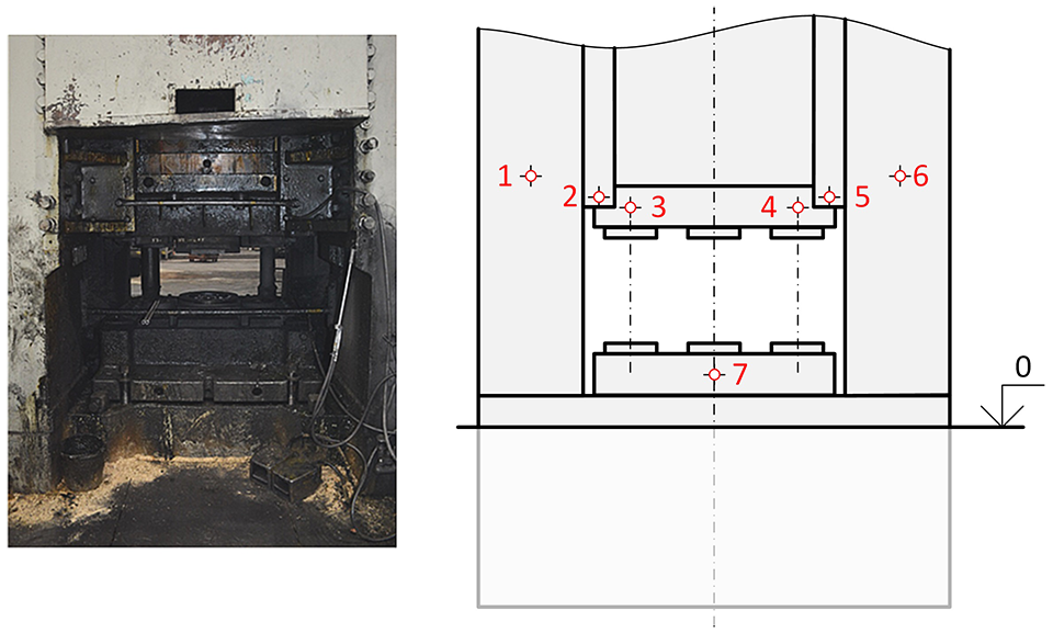
Reference points in thermal cam photo.

View on working place of the press (left) and sketch of reference points for thermal cam measuring (right).
Description of reference points:
center of the left column
bottom of the left ram guiding
upper tool holder left
upper tool holder right
bottom of the right guiding
center of the right column
bottom tool holder center
Temperature measurement at each reference point was performed at intervals of 15 min.
Results of experimental measuring are shown in the Table 1. The analysis of the results is presented in a separate chapter.
Experimental measuring results – temperature values in a reference points while forging [°C].

Virtual simulation of the thermal load of the press caused by the technological process and the subsequent structural analysis
Numerical model the press has been compiled for virtual simulation. The boundary conditions was set to be as close as possible to the real situation during measuring. The thermal load simulation was performed in two steps: the first was preheating of forging tool and second was forging.
Boundary conditions
Preheating
Preheating was computed as a time calculation (Figure 7). According to information from press operator, the heating was set to 60 kW (22 kW for the lower die and 38 kW for the upper die) for 12 h. The heat output was set to the inner surfaces of the die. The initial temperature of the entire press volume was set at 30°C (corresponding to the measurement conditions). After preheating, there is a 30 min delay inserted in the simulation – it leads to stabilization of temperature.

Boundary conditions of thermal load – preheating (left) and forging (right).
The heat transfer methods are:
Convection - for all solids
Radiation
Conduction
The input to the forging part of simulation is the thermal state of the machine after the simulation of preheating. The billet temperature in each die was set to 1150°C and the billet was sequentially switched in positions 1, 3 and 2 (see Figure 7) to maintain a realistic forging times. A single piece 24 sec (3× 8 s) with repeating every 100 s. The simulation was performed as a time calculation for 5 h, which corresponds to an experimental measurement. The heat propagation conditions were maintained from the previous step.
Forging – maximum machine utilization (according to the specified technical parameters)
The boundary conditions of the forging simulation at maximum machine utilization are taken from the simulation of the real forging. They differ in timing of the forging. Maximum utilization of the machine is simulated for continuously repeating of 24 s work cycle.
Structural analysis
Subsequently, the structural analysis was performed to determine the effect of thermal load on displacement. As the input the temperature field representing the status of the press load has been added:
After preheating and 30 min of temperature stabilization.
After 5 h forging according to the real condition.
After 5 h of forging at maximum utilization of the machine.
The boundary conditions were set to make reading of displacements in the X direction (left to right) and Y direction (front to back) simpler. Displacements were evaluated on both ram guides and the opposite contact surface on the ram. Areas penetration of guide surfaces was enabled.
Results of thermal load simulation
The first part of the simulation was preheating of the dies. The actual preheating was carried out with the gas burner. It was substituted by the heat source acting on the surface of the upper and lower dies in the simulation. The following Figure 8 shows the temperature distribution results on the press assembly after 12 h of continuous preheating (left) and after a further 30 min of dwell time (right). The results show that preheating effected only immediate surroundings of the press working area. Temperature values shown in the following figure are measured as a mean for the front surface of the tool.
Display of temperature distribution after 12 h preheating (left) and other 30 min of temperature stabilization (right).
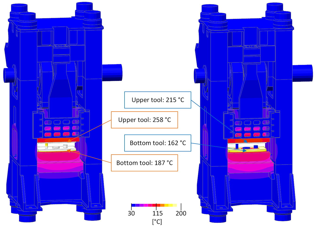
The following part was devoted to simulation of thermal influence during the forging itself. During forging, forgings are regularly inserted into working positions. The following Figure 9 shows the temperature distribution at 2 h (left) and at 5 h (right) from the start of forging. From the graphic presentation of the temperature distribution the confirmation of the results of experimental measurements is obvious – there is a decrease of the temperature during the forging.

Display of temperature distribution after 2 h of forging (left) and 5 h of forging (right).
Results of structural analysis
Structural analysis of the displacement due to thermal load was performed with results of thermal simulation. As the input load the temperature array representing the state of the press after a 30 min delay after the preheating has been added. Subsequently, the temperature array representing the state of the press after 5 h of forging in accordance with the measurement on the real machine has been used – results can be seen in Figure 10. The last simulation was done for continuous forging.

Displacement in X (left to right) direction after 30 min delay after preheating (left) and after 5 h of forging (right).
The main location of interest is the ram guiding. The boundary conditions were set to ease the reading of the ram guiding on the ram side and the press stand displacements. For these surfaces the penetration was enabled.
The displacement values were read as average over the entire area of the guiding. Results of displacement after preheating are collected in Table 2.
Results of displacement in guiding – after preheating (mm).

Results of displacement after 30 min delay after preheating are collected in Table 3.
Results of displacement in guiding – after 30 min delay after preheating (mm).

Results of displacement after 5 h of forging are collected in Table 4.
Results of displacement in guiding – after 5 h of forging (mm).

Analysis of results
Analysis of results of experimental measurement of machine temperatures during forging
Preheating of the tool has become a major influence of the thermal load from the technological process. This was carried out before the operation of the forging.
It is obvious from Figure 11 that the temperatures read at the reference points fall from the initial values from preheating through a whole measurement until they are stabilized. In the case of reference points 1 and 6, that is points on the frame, there is no significant influence from preheating. The technological process forging subsequently raises the temperatures of the reference points on the ram by several degrees.

Development of measurement temperatures in time by each reference points.
The uneven heat load of the ram is given by the unevenness of the preheating, where the difference between the temperature of left and right side of tool holder is 17°C and 5°C for the left and right ram guides at the beginning of the measurement (after the preheating). Those uneven temperatures are equalized after 5 h of technological operation forging. It confirms the fundamental influence of preheating.
Another factor leading to the uneven thermal load may be caused by the feeding of the forging through the left window, where is its temperature higher than when the forging is removed by the right window.
Analysis of results of heat distribution simulation during forging
An example of consensual results of experiment and simulation is a reference point 3 – left side of upper tool holder. Specific comparison is shown in Table 5.
Comparison of experiment and simulation results – values of temperature are in reference point three during forging [°C].
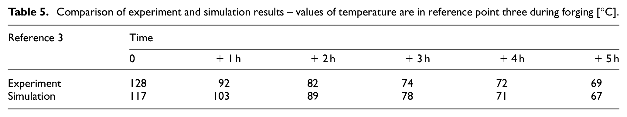
The calculation tends to confirm the cooling machine after initial preheating of the dies. Due to the low forging cycle, there is no additional significant temperature increase at any of the monitored locations.
Due to the low forging cycle, the further calculation for the continuous forging process in a 24 s cycle was carried out.
Analysis of structural analysis results
The results of the virtual simulation of the thermal load of the machine showed that there is the displacements in individually monitored, especially functional parts of the machine. These deform by 0.25 mm in horizontal direction. The stand is stretched by 2 mm.
In the case of real forging, the indicated deformations caused by temperature change would not have a significant effect on the required forging accuracy. In the case of precision forging, where the required forging accuracy is up to 0.1 mm, the thermal influence of the machine would no longer be negligible and could disqualify the usability of that machine.
The component that is the most exposed, both in terms of machine accuracy and temperature influencing, is the ram guiding. With precision forging, the guide clearances are defined in tenths of mm. Depending on the results of the thermal analysis, when the temperature rises, the guide may become seized and the machine may crash. Therefore, the adaptive temperature control of the functional parts is performed on these machines. But it is very energy demanding and expensive.
Conclusion
For the forgings to achieve high accuracy, the technical parameters of the machine must be observed. Such parameters are the clearance in the guided ram, the distance between the upper and the lower tool (affecting the height of the forging), the alignment of the moving parts, and more. Every change of the mentioned parameters results in a change of the dimensions of the forgings and hence its accuracy. Changes to these parameters have a significant effect on the machine’s own operation, and a major change can lead to machine failure. Even without operator influence, these parameters are influenced by the thermal condition of the machine. This implies that the stability of the thermal state of the machine is very important for its accurate and trouble-free operation. Therefore, we focused on the thermal state of the forging press during its operation.
Making measurements directly on the forging machine is relatively difficult and expensive, but the obtained results match the best to actual thermal condition of the machine. Therefore, they are so important. Results from such measurements helps to more accurately determine the boundary conditions for virtual simulation. The fact that virtual simulation correctly simulates the actual thermal state was demonstrated by comparing the results in the previous chapters.
Nowadays the issue of the thermal state of the press is solved by the installation of heating and cooling technology at critical parts in the machine to set the stability of the thermal state. This solution is very demanding on energy consumption and also on the design of the equipment itself.
From the previous measurement and virtual modeling, it is possible to solve this problem in order to reduce energy consumption. Virtual modeling showed that the thermal state of the working space after the initial preheating and during forging is dependent on the thermal capacity of the forgings and the frequency of the forging. Large forgings represent a large heat source and it can heats up the work space at the same forging frequency. At a low frequency of forging the tools must be reheated, while at a high frequency it is also necessary to cool intensively. This phenomenon is a significant energy expense required to maintain the thermal stability of the machine.
From a virtual simulation of the thermal process, it has been recognized that the energy requirement for maintaining the thermal stability of the machine could be greatly reduced by appropriately adjusting the forging frequency.
The following applies:
For each type of forging and its technological processing process there is one optimum forging frequency that guarantees the thermal stability of the machine.
The results of the simulation of the forging according to the real state show that spontaneous cooling occurs at a low forging frequency. (But forging at the maximum possible frequency still leads to loss of heat energy.)
A stable thermal state could be achieved when more massive forgings are forged (the analyzed press still has a reserve).
This means to find what limits of the regulation are economically advantageous to move. But it is clear that the energy consumption of production can be reduced within certain limits.
Footnotes
Handling Editor: James Baldwin
Declaration of conflicting interests
The author(s) declared no potential conflicts of interest with respect to the research, authorship, and/or publication of this article.
Funding
The author(s) disclosed receipt of the following financial support for the research, authorship, and/or publication of this article: This paper has been supported by the project “Manufacturing engineering and precision engineering” funded as project No. CZ.02.1.01/0.0/0.0/16_026/0008404 by OP RDE (ERDF).