
Abstract
The paper deals with the drive options of mechanical presses and their influence on energy efficiency. Although the main focus is on energy efficiency, we also emphasize design and operational issues. The press machine is divided into two separate sections – the machine side and the drive side. The machine side and its efficiency is described using an energy balance formula. We quantify the energy balance for an 80 MN forging press. We describe eight different types of drives from a typical drive with a flywheel to direct drive and their combinations. We describe individual losses and efficiencies for components of the drive side.
Introduction
Forming is one of the most productive and therefore also the most widespread production and processing technologies. However, implementing this technology is very energy intensive. To increase production efficiency, we must pay special attention to forming and look for ways to save energy.
An example of sprocket production can be used as an illustration both as a comparison with machining technology, Figure 1, and as a demonstration of the energy balance in its production by forming.

Sprocket wheel – an example. 1
The graphs in Figure 2 clearly demonstrate the benefits of forming technology over machining technology, not only in terms of energy efficiency.

Comparison of environmental effects of machining and hot forging. 1
Hot forging operations (described in Unver and Kara 2 ) are: Cutting; Heating; Forging; Flash trimming; Finishing; Crack control. An example of chromium alloy steel forging was analyzed in a forge shop with the following results – see Figure 3.
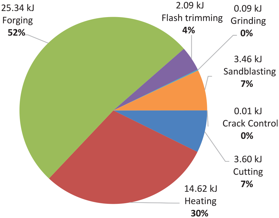
Energy consumption – steel forging facility (case study). 2
Figure 3 shows that the largest amount of energy needed to produce the part is used by the forming process (25.34 kJ, which is 52 % of the energy of the whole production process). This can also be generally applied to other forgings. This is why we decided to look for possible energy savings in this area.
The values correspond to the globally accepted energy values consumed by forging of 128 kJ/kg. 3
The basic energy needs for the production of a product by forming can be divided as follows:
Performing the technological operation – the deformation energy and the associated work needed to overcome the friction between the tools and the formed product.
Operating the machinery – the work required to operate the forming machine, manipulator, transport, etc.
If we want to think effectively about energy savings, we should focus primarily on the areas that are the most energy-intensive, but also where solutions can be expected that could bring significant energy savings.
In the first case, the amount of energy required is largely defined by the technical requirements of the final product and very often changes with the changing product range. In the second case, there is a choice of equipment and the most suitable and efficient one must be selected to produce the product. The machine energy saving solutions are long-term (for the entire life of the machine) and are not so dependent on the range of products produced.
Therefore, we focused on the second case – forming machinery, and the most common type – mechanical crank presses. Because a large number of these machines are in operation, even a small energy saving in their operation will benefit society many times over.
Description of a crank forging press
To help understand the problems of the machine function, here we describe the most frequently used drive systems of crank presses. A flywheel drive with or without a countershaft serves to accumulate the energy absorbed by the impact during forming. A typical arrangement is shown in Figure 4.

Diagram of a forging press with a crank mechanism and a flywheel drive (variant B).
The press (Figure 4) consists of:
Machine part – it is kinetically identical for all crank presses and the energy balance of most presses does not differ much. Energy savings in this part depend mainly on losses caused by friction, or on losses caused by elastic deformations of functional elements. 4
Drive part – there are various design variants. Therefore, it is necessary to pay attention to this part of the drive system to influence its energy consumption by a suitable design and a suitable choice for different types and sizes of crank presses.
Therefore, below we analyze various solutions and use the results to propose new variants of solutions that should have lower energy intensity.
Mechanical crank press drive – analysis of individual systems
The mechanical crank press drive transmits power between the electromotor at the input and the crankshaft at the output. Since the rotational speed of the input and output is different, the drive reduces it. The usual rotational speed of a large press crankshaft is 30 rpm considering a theoretical continuous work cycle, and the rotational speed is 100 rpm for small presses. The usual gear ratio for large presses is 1:30.
Typical drive systems used today
Flywheel on a crank shaft drive (variant A) and flywheel on a countershaft drive (variant B)
The most commonly used forging press drive is a flywheel drive with or without a countershaft. The flywheel serves as an energy accumulator to provide energy in peaks for the forging operation in the machine side of the press. For both variants the motor and the flywheel are coupled by a belt drive. An example of a typical machine layout is illustrated in Figure 5.

Diagram of drive with a flywheel drive (variant A – left) and drive with a countershaft (variant B – right).
For presses that have a smaller number of strokes, thus a smaller number of crankshaft revolutions (these are large presses), a larger reduction ratio is required (approximately 1:30), and then another gear must be used on the countershaft (Variant B). There is a gear in variant B between the countershaft and the crankshaft due to the transmission of high power.
A direct drive with a torque motor (variant C)
Direct drive is typical in that all the power consumption of the press mechanism is covered by a special high-power torque motor. Because the crankshaft speed is low, the torque motor must also be slow running. Torque motors are a special class of brushless permanent magnet synchronous motors.
The direct drive makes use of electric energy accumulation – usually by means of a supercapacitor or an externally located flywheel.
The brake in this kind of drive is only to meet safety requirements. The machine side is braked by the motor itself when it is in generator mode. Hence there is no brake energy loss – only energy loss in the accumulating device.
The direct drive layout (Figure 6) has no clutch and there is no clutch energy loss.

Diagram of drive with direct drive (variant C).
Comparison and results of the analysis of the most frequently used drives
Variant A
This is the most frequently used drive system for crank presses due to its simple design. Of all the flywheel drives its drive is the stiffest from the motor to the crankshaft, it has the lowest energy losses in coupling (there is only a belt coupling from the motor to the flywheel) and is the cheapest thanks to its low technological manufacturing requirements. Its drawback is the significant weight of the flywheel and the high dynamic loads linked to it. It is suitable for presses where a smaller reduction ratio from the engine to the crankshaft is sufficient (with a belt approximately 1:6; with a gear approximately 1:9). It is used mainly with smaller presses with nominal forces up to 20 MN.
Variant B
This is the second most commonly used drive system for crank presses. To increase the reduction ratio from the engine to the crankshaft, a countershaft is inserted into the drive system, on which the flywheel is located. Because the flywheel has a higher speed on the countershaft, it can weigh less than in variant A. However, inserting the countershaft reduces the rigidity of the transmission and increases the losses by another gear pair. This drive is also more expensive and technologically more complicated to manufacture. However, despite these disadvantages, it is the only solution for drives where a large transmission between the engine and the crankshaft is required (approximately 1:30), which is used in large crank presses (from 25 MN).
Variant C
This is a direct drive with a torque motor located on the crankshaft. This drive system eliminates the need for a clutch and gears. The brake is mainly used to fix the position. This drive has the best mechanical efficiency and therefore the greatest rigidity of the drives. However, torque motors have lower efficiency than commonly used electric motors. These motors are very heavy and very expensive. Their operation is problematic because they draw high currents at peak times, which most electrical networks cannot withstand. Therefore, energy accumulators must be used, which, however, reduce the efficiency of the entire drive and make it more expensive. So far, these drives are used in small, and occasionally medium presses, especially for technologies where it is necessary to regulate the speed during the stroke.
Proposal for new, more advanced variants of drive systems
The following list contains non-standard types of drives.
A torque motor drive with a gear pair (variant D)
As the speed of a motor decreases, its efficiency usually decreases and its weight and price increase considerably. Therefore, it is possible to insert a gear between the torque motor and the crankshaft, which allows the use of a motor with higher speed and lower weight, greater efficiency, and lower cost (Figure 7). This compensates for the reduction in efficiency by the gear. This drive system works on the same principle as variant C, but it is cheaper and lighter.

Diagram of drive side with a direct drive with an intermediate gear (variant D).
A drive with a flywheel on the motor shaft (variant E)
The main advantage of placing the flywheel on the motor shaft (Figure 8) is lowering its weight while keeping the accumulated energy the same. This modification is based on placing the flywheel on a shaft with higher rotational speed, which leads to significant lowering of its moment of inertia.

Diagram of drive with a flywheel drive with a flywheel on the motor shaft (variant E). 5
The disadvantage of moving the flywheel in front of the belt drive is its transient load with considerable power. The transmitted power can reach the limit of the possibilities of the belt transmission. After that, it is necessary to use a more expensive gear.
The benefit of this drive system is the greater dynamic stability due to smaller rotational masses, and greater efficiency can be expected when using a gear.
If a larger reduction ratio is needed, a countershaft can also be used with this drive. This drive system is recommended especially for presses up to 20 MN.
A flywheel drive combined with torque motor (variant F)
This is a drive that combines the advantages of both flywheel and direct drives (Figure 9). The direct drive with the torque motor is used to accelerate and brake the press mechanism. The flywheel drive is used to perform technological operations where peak power is needed. Because the clutch is a part of the flywheel side, it engages with the shaft on the drive side at a synchronous speed, and thus the slip and wear are minimized.

Diagram of drive with a combination of a flywheel and direct drive (variant F).
Unlike the current design, this type of drive might expand the use of torque motors for medium sized presses, that is around 25 MN. It could mean significant energy savings compared to conventional flywheels.
A flywheel drive with a planetary gearbox inside the flywheel (variant G)
A gearbox may be included to achieve a sufficient reduction ratio higher than with a countershaft (Figure 10). The gearbox means there does not have to be a countershaft, so the flywheel can reach higher speeds and thus be smaller.
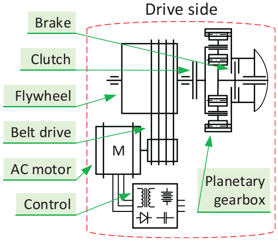
Diagram of drive with a flywheel drive with planetary gearbox (variant H). 6
This type of drive reduces the weight of the rotational masses, better energy efficiency, and high dynamic stability is predicted.
A flywheel drive with a torque motor (variant H)
A flywheel drive with a torque motor uses the flywheel to accumulate energy for the technological operation. A torque motor is used to charge the flywheel, which charges only in the part of the stroke between top dead center and bottom dead center (Figure 11).

Diagram of drive with a direct drive with flywheel (variant H).
This drive system broadens the possibility of using torque motors even for large presses and lowers the losses from electrical accumulation.
Comparison and results of the analysis
To achieve energy savings in mechanical crank press drives it is important to choose a suitable drive system in respect to the technological purpose, design, and size of the press. In this sense, there are still considerable reserves in the current production ranges of crank press producers.
Therefore, we carried out the analyses described above to enable us to make the right choice from the different drive systems. Currently, the energy efficiency is around 40%, which is not much. It can be assumed that with the correct choice of drive the efficiency could increase by up to 10%, which means huge savings for units with power of MWs.
Variant D
An improved variant C with all its advantages and disadvantages. Lower energy demands are expected. For use with small and medium presses.
Variant E
The benefit is lower weight of rotating masses, greater dynamic stability, and the assumption of better efficiency. For use with small and medium presses.
Variant F
The benefit of this system is the possibility of using a torque motor drive with a range of medium-large presses around 25 MN. Energy savings can be expected compared to existing drive systems.
Variant G
The advantage is that a relatively large countershaft is eliminated. It is also possible to use a gear ratio greater than 1:30. The total weight of the machine can also be reduced. At the same time, all the advantages of the classic flywheel drive are preserved. It is not limited by the size of the machine.
Variant H
It is not necessary to install electrical energy storage, as the energy consumption peaks will be covered by the energy stored in the flywheel. This extends the use of direct drive to presses with greater forces. It is also possible to assume energy savings by reducing losses in the accumulation of electricity to cover energy peaks.
An analysis of energy flow in a crank press
Energy balance of a work stroke on the machine side of a crank press
The energy balance equation (the amount of energy which a drive must deliver to a mechanism (machine) to carry out its technical operation) is solved for one work cycle during continuous operation of the machine.

The energy balance of a forming machine can also be evaluated for a discontinuous work cycle. A discontinuous work cycle occurs when, after each technological operation, the crank shaft and connected ram stop in the upper dead center of the mechanism. This means that energy is evaluated from the time when the front shaft and crank shaft of the mechanism connects with the clutch until the time when the front shaft and crank shaft of the mechanism disconnects from the clutch and the crank shaft is stopped by the brake. Energy which is needed to start the machine is not considered in the energy balance formula. 7
An example of energy balance is described for a mechanical forging press with a nominal force of 80 MN. The force-displacement curve for closed die forming processes is simplified according to Kamelander, see Figure 12.8,9

Force-displacement curve representing closed die curve for 80 MN crank press.
For such an operation and known press dimensions (and other operational data) it is possible to describe the work of elastic deformations, the work of friction and the work of the acceleration of masses. The work of gravity is not considered within this example (the start and end position are the same).
The result of such an energy balance of the machine side is the realization that only 43% of all the energy used in the machine side is consumed by the technology process itself (useful work (Au)) (Figure 13). Other partial works are energy losses. The start-up work (Aa) that describes the energy necessary to set the mechanism in motion is then dissipated in the brake at the end of the work cycle because a discontinuous work cycle is assumed. The highest energy loss is dissipated in friction (Friction work (Az)). The lowest energy loss is dissipated by machine stretching, mainly in its frame (work of elastic deformations (Ad)). 10
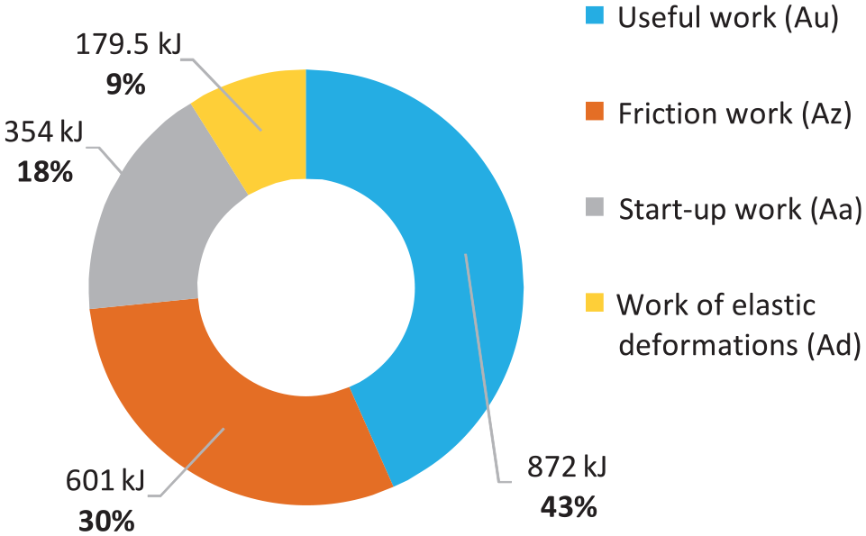
Distribution of energy usage.
Since we have almost exhausted all the possibilities for saving energy on the machine side, our objective now shifts to saving energy on the drive side of the mechanical press.
Locations of energy losses in the drive
We chose Variant B as an example. The flywheel drive with a countershaft is described in the following figure in terms of energy losses.
In a typical drive (Figure 14) the locations of energy losses are:

Locations of energy losses in a typical drive with flywheel and countershaft (variant B).

Work lost by brake
Work lost by the brake approximately equals the start-up work. This is the energy of the mechanism in motion that needs to be dissipated when the mechanism needs to be stopped (usually before reaching top dead center)
It should be noted that the efficiency of the press is examined as a whole, and this work needs to be taken into account only once.
It is possible to lower the work lost by the brake by lowering the kinetic energy of the machine side. This can be achieved by lowering the moment of inertia of the mechanism.
This lost energy might be decreased or completely eliminated if energy recuperation is implemented. In practice attempts are being made to recuperate energy by its transformation into hydraulic, pneumatic, or electrical energy that is afterwards available to start-up the mechanism.
The total calculated work lost by the brake for a press of 25 MN is 100 kJ, which is approximately 45 % of useful work (Au).
Work lost by clutch
The clutch in the drive of press typically serves to connect and disconnect the flywheel (A) to the press mechanism (B) (Figure 15). Usually a dry friction air-operated disk clutch is used.

Schematic representation of connection of rotating masses by a coupling.
Assume that:
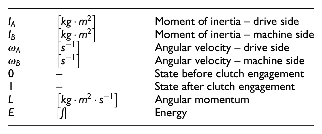
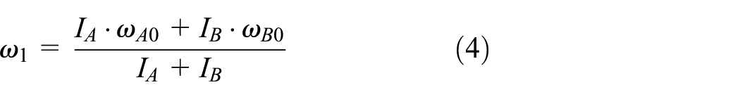
Determination of energy loss by taking the law of conservation of angular momentum and substituting it in the law of conservation of energy
Determination of the work lost by the clutch is based on the law of conservation of angular momentum and the law of conservation of energy.
The law of conservation of angular momentum states that the angular momentum of an isolated system of bodies is conserved. Then the following is valid:


The law of conservation of energy states that energy can neither be created nor destroyed; rather, it can only be transformed from one form to another. The energy of the clutch before engagement is equal to:

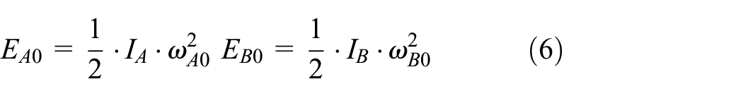

The decrease of kinetic energy after connecting both bodies is given by an irreversible increase of internal energy. In this case it is thermal energy. It is an inelastic impact. In an ideal inelastic impact the two bodies have the same velocity after collision (they do not move with respect to each other).
The energy of the system after clutch engagement and stabilizing rotational speed is equal to:


Loss of kinetic energy is equal to:


Energy loss solved by this method is ideal. In reality the energy loss will be higher due to clutch slippage caused by slow clutch engagement.
From Figure 16, it is clear that clutch energy loss is dependent on the flywheel size. Horizontal axis of the graph describes ratio between moments of inertia of drive side to inertia of machine side. The blue curve (left vertical axis) describes ratio between energy lost by clutch to energy transmitted by the clutch (kinetic energy of machine side after clutch engagement). This ratio is better for bigger flywheel but what cannot be seen from it is that with bigger flywheel the total energy lost (the green curve) is higher too. The red curve (right vertical axis) describes decrease of rotational speed from initial to final speed. With bigger flywheel the rotational speed is less affected by clutch and therefore the press productivity is higher.

Dependence of energy lost by clutch on the moment of inertia of the flywheel.
It is obvious that proper setting of flywheel size influence total energy lost. With bigger flywheel energy lost is growing but rotational speed drop is reduced too – flywheel size must be optimized to fit intended use.
The total calculated work lost by the clutch for a press of 25 MN is 95 kJ, which is approximately 43% of useful work (Au).
Work lost by shaft support bearings
Drive shafts are commonly seated in self-aligning bearings (double-row spherical roller bearings). Self-aligning bearings are used because of their ability to accept minor misalignments and withstand possible imprecisions in the manufacturing of the press stand. Because of its line contact, this type of bearing has a relatively high energy loss.
Bearing manufacturers are also occupied with energy demands. The following example (Figure 17) is from a Schaeffler 11 symposium where different car gearbox shaft bearings are shown. The article Innovative Bearing Concepts for the Powertrains of the Future by Georg von Petery and Reinhard Rumpel deals with new low friction bearing design. The article shows that consistent optimization of bearing designs might help further lower the friction.

Friction loss (top) and rating life (bottom) for the gearbox shaft with different bearings. 11
Bearing manufacturers themselves are occupied with energy demands. The example is on following figure from Schaeffler symposium where different car gearbox shaft bearings are shown. Article Innovative Bearing Concepts for the Powertrains of the Future by Georg von Petery and Reinhard Rumpel deals with new low friction bearing design. This article shows that consistent optimization of known bearing designs might help furthermore lower the friction.
The bearing energy loss of a forging press with a nominal force of 25 MN is analyzed with consideration of the particular types of bearings and lubrication. 12 This analysis was performed for both A and B bearings as shown in Figure 18.
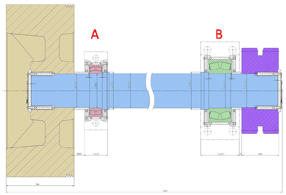
A specific bearing of a countershaft of a forging press 25 MN.
The analysis was performed for two load cases according to the loading of the countershaft.
From the results of the analysis (Table 1) it is clear that optimization of the original countershaft bearing design can achieve energy savings. While being relatively high, in the context of the whole machine the contribution of these savings are low. In a mechanical press with a nominal force of 25 MN, the energy saved by the new design is 1.1 kJ while useful work (Au) for one cycle reaches 220 kJ.
Comparison of energy losses for a specific countershaft bearing (highlighted in bold) and its alternatives and various lubricants.

The total calculated work lost by the countershaft bearings for a press of 25 MN is 6.5 kJ, which is approximately 3% of useful work (Au).
Efficiency of gearing
Gearing is used when a flywheel is put on a countershaft. Only gearing is able to transfer the required power from the flywheel to the crank mechanism. The efficiency of spur gearing itself is stated to be 98%–99%, which is quite high. 13
Ways to affect gearing efficiency are:
A higher load during running-in yields higher gear mesh efficiency compared to a lower running-in load. 14
The tested superfinished gears exhibit an overall higher efficiency when compared to ground gears. 15
The dependency of gear meshing efficiency on the manufacturing accuracy is shown in Table 2.
Meshing efficiency of cylindrical gear. 16

Efficiency of belt drive
Typically, the efficiency of a belt drive is considered to be 90%–98%. These numbers are given by manufacturers with the words “up to,” so rather lower values can be expected. Furthermore, there are no regulations on how the efficiency measurements are carried out, so it is not clear under what conditions the manufacturers reach their stated values. 17
Experimental verification of a belt transmission efficiency was performed for various belt types (Table 3). The following Table 3 lists the types of belts, their declared, and measured efficiency.
Nominal efficiency per type of belt (manufacturer’s data and measurement). 17
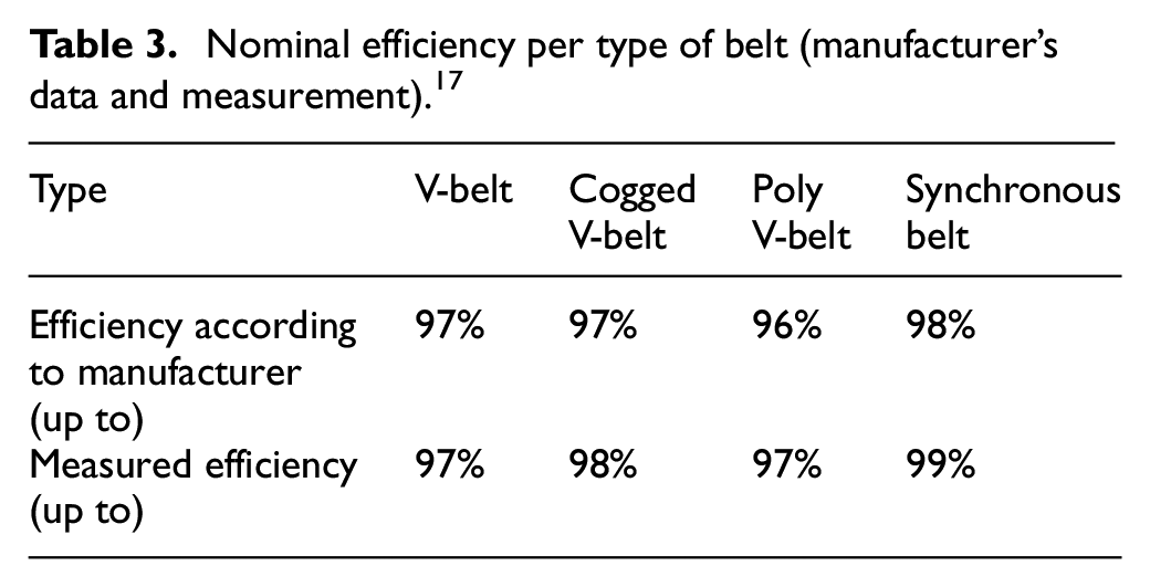
It is clear from the examples that the efficiency of belt transmissions is relatively high. However, if an unsuitable belt transmission is used, the efficiency can drop significantly. Therefore, it is necessary to pay due attention to the belt drive. For example, improper installation of pulleys, worn grooves, or improper preload can reduce efficiency by up to 10%. 18
Efficiency of the electric motor
According to EU Directive 2005/32/EC, only motors with a minimum specification of IE3 can be used in the EU from 2015 onwards.
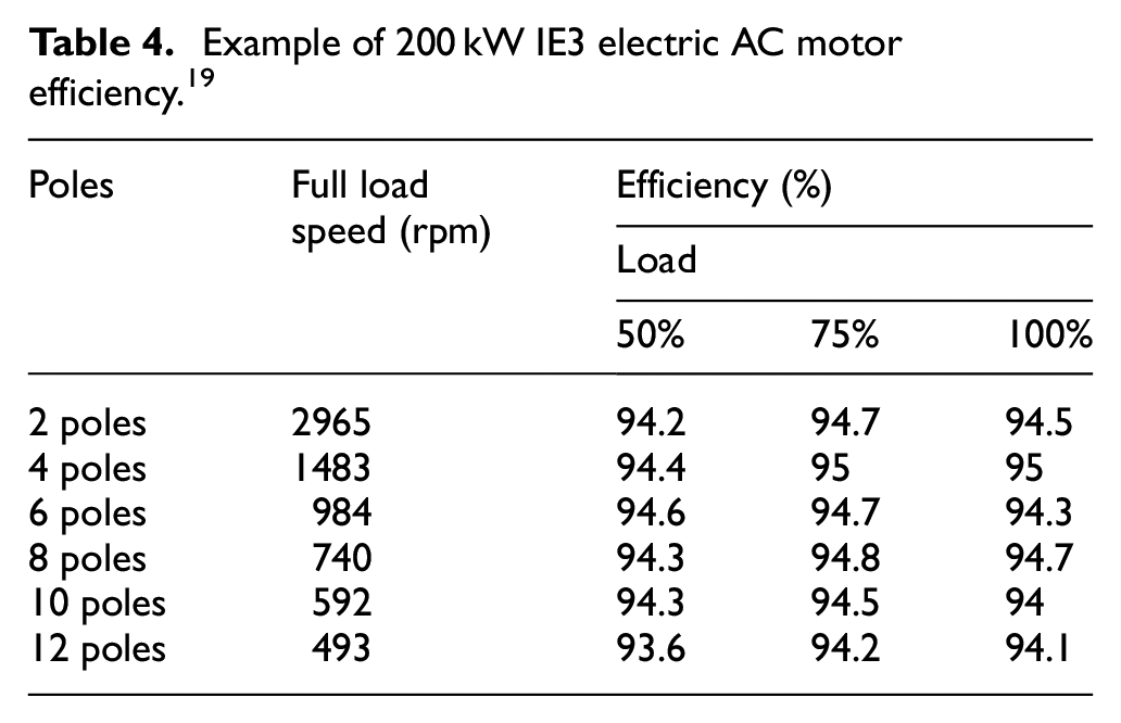
Asynchronous motors are used for conventional drives. Since the required rotational speeds of an eccentric shaft are low, it is advantageous to use slow-running motors. Slow-running motors are multi-pole (8- to 12-pole). The efficiencies stated by the electromotor manufacturers are listed in Table 4.
Example of 200 kW IE3 electric AC motor efficiency. 19
Electric motor losses come from five main domains (see Figure 19):

Percentage distribution of losses in a typical AC electric motor. 20

For direct drive, special synchronous motors, so-called torque motors, are used. These are characterized by being slow-running (up to 75 rpm) and high-power (up to 4.5 MW). 21
Efficiency of the electricity source
The control of the electric motor itself has its losses. An asynchronous motor is typically connected to a frequency converter, which has an efficiency up to 97%, see Figure 20.
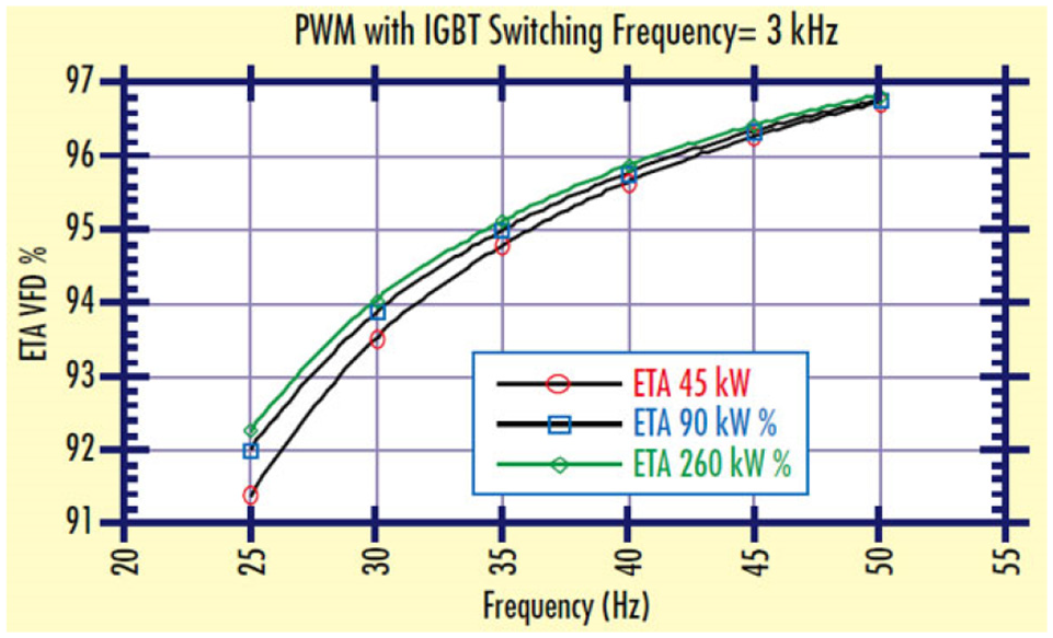
Frequency converter efficiency as a function of the frequency. 22
The situation is more complicated when torque motors are used. If a torque motor is used as the direct drive of a press with uneven energy consumption, it is necessary to ensure the accumulation of electrical energy. A comparison of the possibilities of electric energy accumulation is shown in the following graph (Figure 21). 23
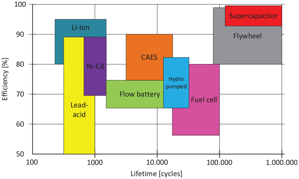
Comparison of electricity accumulators by efficiency and lifetime in cycles. 23
Results and discussion
A significant result of this research is description and understanding of estimated partial energy losses that appear in the presented drive variants, see Table 5. When all unknown values of energy losses or efficiencies are put in the Table 5 it is possible to calculate total efficiency of mechanical crank press drive.
Occurrence of energy losses and energy transfer efficiencies for each drive variant.

Conclusion
The Research Center for the Design of Forming Machines at the University of West Bohemia in Pilsen, in cooperation with manufacturing companies, has been dealing with the issue of the intensity of energy use in forming machines for a long time. We monitor the current situation, analyze the acquired knowledge, and use that as a basis for designing new solutions. The information provided in this article is a brief extract of some of the results obtained from our development and research activities.
At present, the typical energy efficiency of crank presses is around 40%. Although the above design suggestion can increase the efficiency, we cannot assume that the overall efficiency will significantly exceed 60%. From the above, it is clear that energy savings in the drives of mechanical presses can be found in using right choice of drive system for different pressing processes. This also takes into account the size of the press force and its design. By choosing the right drive system, energy consumption can be reduced by up to approximately 10%, especially if we take into account the possibility of braking energy recuperation. However, the increased costs of a more energy-efficient drive system often remain an issue, which often discourages investors when buying a new machine. Investors do not realize that these machines will often be in operation for several decades and that their increased investment will pay off several times over.
An attention must be paid to flywheel size when there is a slip on clutch. With smaller flywheel the slip loss descend but also rotational speed descend what influence electric side of drive and, what is more important, productivity of press.
Another way to reduce the energy demands of a machine is the optimal choice of its components from the energy point of view, as stated in the final part of this paper. However, these savings are only in the range of a few percent, often in strict compliance with the technical operating measures. But even a figure of several percent with such large energy consumption is significant.
It can be said that it is no longer possible to expect any significant increases in efficiency in the crank mechanism of crank presses – that is reducing their energy demands.
In order to further reduce the energy demands of forming equipment, it will be necessary to look for new principles of the forming method itself.
The paper presents completely original drive systems developed at CVTS (Research Center for the Design of Forming Machines), some of which are legally protected. 24 The contribution of this paper is mainly the analysis of existing crank press drives, which has not yet been published elsewhere to a similar extent.
Footnotes
Handling Editor: Chenhui Liang
Declaration of conflicting interests
The author(s) declared no potential conflicts of interest with respect to the research, authorship, and/or publication of this article.
Funding
The author(s) disclosed receipt of the following financial support for the research, authorship, and/or publication of this article: This paper has been supported by the project “Manufacturing engineering and precision engineering” funded as project No. CZ.02.1.01/0.0/0.0/16_026/0008404 by OP RDE (ERDF).