
Abstract
In industry, high-density packaging technology is an unavoidable requirement. Therefore, the drilling hole of printed circuit boards, PCB, requires being much smaller, even down to 0.1 mm or less. Drill fractures are frequently found in the micro drilling process due to the micro scale, hole-location errors, reaming. In all micro drilling failure cases, there existed a large vibration or instability is frequently found because of the insufficient rigidity of supports for a system with a super-high spinning speed. To improve the drilling quality and avoid drill breakage, the effects of support stiffness and high rotational speed of the vibration in the micro drilling process must be studied. Most investigations on the vibration of micro drilling are focused on only drill self-structure. However, in an actual engineering application, the micro drill must be attached in a bearing spindle system. This study considers the vibration of a micro drill with a gas bearing spindle. Hence, it includes the effects of the rotation speed, air pressure, and clearance of gas bearing on the vibration in a micro drilling process. After constructing the governing equations of the system, the numerical analysis by the Fortran programming is performed to solve for the frequency and amplitude response of the spindle system over time. The results indicated that the spindle with the gas bearings effect increased the vibration in the micro-drilling process.
Introduction
In the cutting process of an actual machining application, the machining tool must be attached to a spindle with bearings. However, most investigations on the vibration of micro drilling are focused on only drill self-structure. In this study, the vibration of a micro drill with a gas bearing spindle is investigated. Hence, the effects of the spindle and bearings on the vibration of a micro drill must be considered in the machining process. Because this study focuses on micro drilling, a high-speed spindle is an unavoidable structure in the machining system. Gas bearings are frequently used to support high-speed spindles to reduce friction. Therefore, the gas bearing effect of a high-speed spindle on the vibration in a micro drilling process is considered in this research.
The spindle is the key component of the machining system and it affects the dynamic performance and capabilities of the system in the machining process. Only considering the spindle system effect is inadequate because the bearings can also significantly affect the dynamics of the machining system. Therefore, both the spindle and bearing effects in a micromachining system must be considered. In high-speed micromachining, the generation of high temperatures must be avoided. Therefore, non-contact gas bearings are considered in this study. Some researchers1,2 have focused on the dynamic response of a spindle supported by bearings. This dynamic response affects the dynamic characteristics of a machining system. Studies as Agrawal 3 and Holster et al. 4 have investigated the performance and properties of gas bearings. The application and design of gas bearings are discussed by Lie. 5
Machining processes, such as drilling and milling, are frequently used in manufacturing to produce many goods. A precisely drilled hole, which requires an accurate drilling process, leads to a high-quality product. However, hole-location errors, reaming fractures, and drill fractures can occur during the machining process, which leads to a poor-quality product. Understanding the dynamic performance of a drill in the drilling process is essential, especially in high-speed micro drilling. In this study, the effects of the spindle and bearings in a high-speed micro drilling process were considered. To investigate the drilling problems in micro drilling, normal drilling was first examined. Breakage is the most common cause of drill failure. An investigation as Shaw 6 found that drill breakage usually occurs because of excessive drilling force in the drilling process. Only a few studies have investigated the dynamic properties in a drilling process that lead to undesirable effects such as chatter and drill breakage. Few investigators have examined this problem, presumably because such effects are always believed to be caused by the drill structure. For traditional drilling analysis, the researchers7–9 have focused on the drill structure and reported on the vibrations of a drill simulated as a pre-twisted beam. Some studies10,11 have investigated the buckling load and natural frequency of a drill bit. Mathematical models on complex drill bits have been used to estimate the cutting and dynamic properties in the drilling process. 12 A complex geometry or the cutting chip affects the cutting and dynamic drill bit properties. Even a small variation in the complex geometry or symmetry could significantly affect the cutting and dynamic properties of a drill. The present investigation can provide useful information for drill bit design. A study 13 examined the instability in a drill and reported that the effects of the rotational speed, the pre-twisted angle, and a constant axial force may change the dynamic instability.
Micro drills are frequently employed in the electronic packaging industry to cut micro holes. Some studies14–16 have focused on investigating micro drills. Moreover, the micro drill structure problem has attracted the attention of certain researchers, such as Hinds and Tyreanor, 17 who studied the micro drill stress with a constant drilling force. However, the cutting force acting on a drill is time-dependent in an actual drilling process. Therefore, micro drills with time-dependent cutting force were also considered in this study. Studies as Nam et al. 14 and Durão et al. 18 have examined the cutting quality in a micro drilling process. A few researchers as Huang 19 and Huang and Kuang 20 have studied the dynamic properties of a micro drill in a drilling process. Currently, the development of a Micro Drill Bit and studying the performance in micro drilling into hard-brittle materials were attracted respectively to study by Fu et al. 21 and Cheng et al. 22
In rotating machinery, ball bearings are frequently used to support the rotating spindle. Therefore, many investigations on bearing spindle systems have focused on spindles with ball bearings. In these investigations,22–24 the influences on dynamic response of a spindle supported by bearings were studied. The bearing changes the stiffness of the entire spindle system and also considerably affects the system properties at high speed.1,2,25,26 However, in a system with a high rotating speed, the use of a metal ball bearing is unsuitable because of the friction heat generated. Therefore, to generate the high spindle speeds required in micro-machining, gas bearings are frequently used. Some researchers27,28 have studied the performance and properties of gas bearings. Lie 5 investigated the application and design of gas bearings. Recently, the investigations as An et al. 29 and Jedrzejewski and Kwasny 30 focused on dynamic characteristics or modelling of a high-speed spindle with gas and especial ball bearings, respectively. However, only focusing the drill structure and neglecting the effect of the spindle with bearings on the vibration of a micro drill, studied by the previous investigations, would occur inaccuracy. So, both the spindle and bearing effect on the vibration of a micro drill is considered in this investigation. In an actual micro drilling process, the high-speed rotation, gas bearings, and time-dependent drilling force may significantly alter the drilling quality and drill fracture. In this study, the vibration of a drill in a micro drilling process using gas bearings was considered.
Equations of motion
A micro drill with a spindle and gas bearings was considered in this study. The spindle supported by bearings is displayed in Figure 1. Figure 2 illustrates a simple model for this spindle with bearings. In this model, the stiffness of the bearings can be simulated as a massless spring. Both ends of the spindle were supported by the bearings (springs). The rotational speed (Ω) of the spindle was examined.
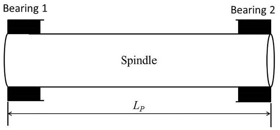
Sketch of a spindle supported with bearings.
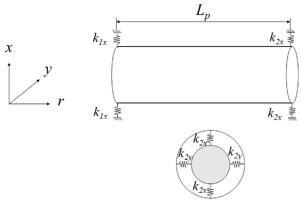
Simple model of a spindle supported with bearings.
Model for a spindle with a bearing system
In this study, up(r,t) and vp(r,t) denote the two transverse flexible deflections of the spindle system; Ip and Ep represent the area inertia and Young’s modulus, respectively; r and t represent the axis and time displayed in Figure 2, respectively; and Lp denotes the length of the spindle. According to Huang, 31 the kinetic energy of the spindle system can be represented as follows:

The strain energy is given as follows:

The strain energy caused by the bearings (springs) is given as follows:

where kx1: the stiffness of the bearings for u deflection at position r1
ky 1: the stiffness of bearings for v deflection at position r1
kx 2: the stiffness of bearings for u deflection at position r2
ky 2: the stiffness of bearings for v deflection at position r2
According to the Hamilton principle, the equation of motion of a spindle with a bearing system can be derived as follows:
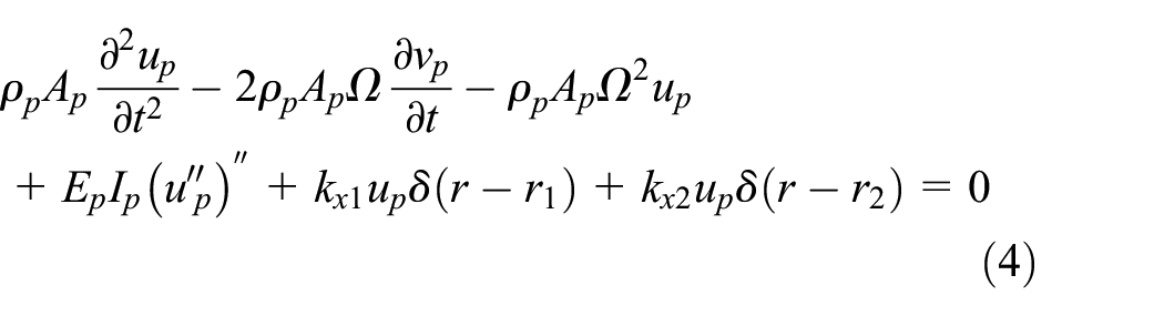
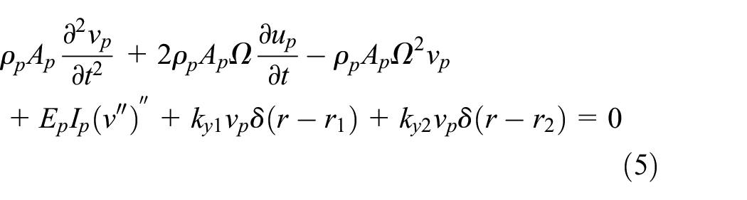
where ρp is the density of the spindle, Ap is the cross-section area of the spindle,
The boundary conditions are as follows:


By using the Galerkin method, the equation of motion in the matrix form of the system can be derived, and the solutions are assumed as follows:


and

The equation representing the motion of the spindle system with bearings can be rewritten as follows:

where
Gas bearing model
In actual application, a high-speed spindle is essential for micro drilling. Gas bearings are frequently employed to support high-speed and light cutting systems because these bearings can maintain a low temperature in the system. Gas bearings have been frequently used to support high-speed spindles in the micro drilling of printed circuit boards. Therefore, micro drilling spindles with gas bearings are of interest. The stiffness of the gas bearing can be represented as follows 5 :

In the aforementioned equation, W and h represent the work caused by the lubricant pressure and the clearance of the gas bearing, respectively. Therefore, the stiffness of the gas bearing can be rewritten as follows:

In the aforementioned equation, Cg is the radial clearance of the bearing, Lg is the length of the bearing, Dg is the diameter of the bearing, Ps is the provided pressure, Pa is the atmospheric pressure, and ε is the eccentric ratio of the bearing.

In the aforementioned equation, the non-dimensional gas bearing stiffness (

where the viscosity is represented as
Micro drill model
A sketch of the stepped micro drill is displayed in Figure 3. This micro drill comprised a shank, tapered shank, and drill body. Therefore, a stepped pre-twisted beam was employed to simulate the drill. The micro drill (a cantilever stepped pre-twisted beam) had a constant rotation speed of Ω. The total length of the micro drill was Ld. The diameter and length of the shank of the drill are D and L1, respectively. A microscopic view of the micro drill cross-section is illustrated in Figure 4. A rectangular drill cross-section was considered in this study because this cross-section shape of the drill is similar to a rectangle as shown in Figure 4. According to Huang, 19 the micro drill body can be simulated using a pre-twisted beam. The notations t0 and b denote the thickness and breadth of the drill body, respectively. The terms ui(r,t) and vi(r,t) denote the two transverse flexible deflections of the ith step-section of a micro drill (i = 1,2,3). Three equations of motion can be derived for the micro drill because it has three stepped components. The equations of motion for the micro drill shank, which is the first step-section of the drill, can be derived as follows:


where


Sketch of the stepped micro drill.

Cross-section photo of the micro drill. 19
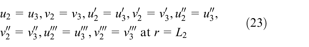
The equations of motion for the tapered shank of the drill can be represented as follows:

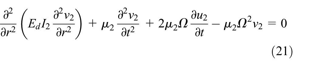
In the aforementioned equations, the tapered shank boundaries are as follows:

The mass per unit length (
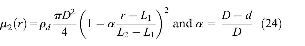
where d is the smallest diameter of the tapered shank. The moment of area (I2) can be expressed as follows:

Finally, the equations of motion for the drill body are derived as follows:


where
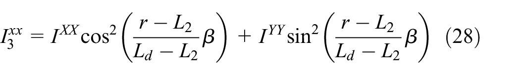

where


and


Drilling process model
A time-dependent boundary and thrust force were employed to simulate the micro drilling process.
20
The time-dependent drilling boundary can be simulated as a moving Winkler-type elastic foundation
2
(Figure 5). Uniform distribution stiffness (
Sketch of the micro drilling process. 20
As


As


As


The equations of motion for the displacement of the micro drill are given as follows:


The non-drilling displacement into a workpiece can be represented as follows:

For the sake of convenience, this non-dimensional drilling displacement can be expressed as follows:

where f is the drill feed velocity. By using the Galerkin method, the matrix form of the equations of motion in the drilling process is given as follows:

where
Micro drill with a gas bearing spindle system
The total length of the micro drill with the spindle system was L = Lp+ Ld. The two lateral displacements u and v for the micro drill with the spindle system are as follows:


The Galerkin method was used to derive the matrix form of the equations of motion for the micro-drilling system. Therefore, the solutions can be assumed to be as follows:


where


By using the Galerkin method, the matrix form of the equations of motion of the micro drill with a gas bearing spindle system can be represented as follows:

where
Result and discussion
The vibration in a micro drilling process using a gas bearing spindle was investigated in this study. The diameter of the spindle (Dp) was considered to be 0.02 m, and the length of the spindle was considered to be 0.1 m. For the gas bearings,
5
the eccentric ratio (
Micro drill breakage is the most common cause of drill failure in the drilling process. In the cutting process, when contact and drilling forces act suddenly on the drill, the drill undergoes large vibrations, which cause buckling and breakage. The effects of a spindle and bearings on the vibration in a micro drilling process were considered in this study. Previous studies10,11 have only considered the effect of the drill structure on the vibration in a drilling process, which is inadequate because the spindle and bearings affect the drilling process in actual applications. Table 1 presents the variation in the natural frequencies of a micro drill with and without the effect of spindle bearings. It shows the lowest eight natural frequencies of the micro drill. When considering only the drill structure, the lowest natural frequency of the micro drill is 36,928 Hz. However, when the effects of the spindle and bearing system are considered, the lowest natural frequency of the micro drill decreases to 2701 Hz. Thus, the natural frequency of a micro drill considerably increases if the effects of the spindle and bearings are not considered. The vibration of a micro drill in a drilling process was examined in this investigation. Since a time-dependent boundary is found in the micro drilling process, the natural frequency of the drill does not remain constant during the process. For convenience, this study shows only the first natural frequency of the micro drill system. The variation in the natural frequency of the micro drill in the drilling process is displayed in Figure 6. Figure 6(a) illustrates the natural frequency in a drilling process when not considering the effects of the spindle and bearings. Figure 6(b) depicts the natural frequency when considering the consequences of the spindle and bearings. The drill just entered the workpiece at the time t = t*. The natural frequency of the micro drill remained constant when it had not yet entered the workpiece. When the drill just entered the workpiece at the time t = t*, the natural frequency of the micro drill suddenly decreased. This phenomenon was because the drill was suddenly acted upon by a cutting force at the drilling time t = t*. However, when t > t*, the natural frequency of the micro drill increased with time. The stiffness of the time-dependent boundary of the micro drill changed from weak to strong when t > t*. As displayed in Figure 6(a) and (b), the natural frequency in micro drilling exhibited similar variations when the effect of the spindle bearings was considered and not considered. However, the natural frequency was overestimated without spindle bearings effects. Figure 7 displays the difference of the natural frequency of the micro drill between considering and not considering the effects of the spindle bearings during the drilling process. In both situations, the natural frequency of the micro drill was constant when the drill did not enter the workpiece. The variation in the natural frequency was considerably larger when considering the effects of the spindle bearings than when not considering the effects. Hence, when only considers the structure of the micro drilling system and neglects the spindle bearings effects, the variation in the natural frequency would exhibit a noticeable decrease.
The variation in the natural frequencies of a micro drill with and without the effect of spindle bearings.


The variation in the natural frequency of the micro drill in the drilling process: (a) without spindle bearing system and (b) with spindle bearing system.

The variation in the natural frequency of the micro drill during the drilling process when considering and not considering the effects of the spindle bearings.
This study also examined the time response in micro drilling. Figure 8(a) displays the time response when considering the effects of the spindle bearings. In the drilling process, the vibration amplitude of the micro drill was almost constant when it did not touch the workpiece. The vibration amplitude suddenly increased markedly when the drill just into the workpiece at the time t = t*. This phenomenon agreed with the results displayed in Figure 6 and was due to the sudden drilling force acting on the drill at the time t = t*. When t > t*, the vibration amplitude decreased as the drill entered further into the workpiece. Figure 8(b) illustrated the time response when not considering the effects of the spindle bearings. The vibration phenomenon was similar when considering and not considering the spindle bearings effects. However, the vibration amplitude decreased markedly when not considering the spindle bearings effects. Thus, the spindle bearings considerably affected the dynamic properties of the micro drill in the drilling process. The effect of the applied air pressure of the gas bearings on the dynamic properties of the micro drill in the drilling process was considered. Figure 9 displays the variation in the natural frequency of the micro drill in a drilling process with different applied air pressures. The results indicated that the natural frequency in the drilling process increased as the applied air pressure increased. Figure 10 illustrates the variation in the natural frequency of the micro drill in a drilling process with different rotational speeds. The first natural frequency in micro drilling increased as the rotational speed increased. Figure 11 showed the effect of the eccentric ratio of the gas bearing on the dynamic properties in micro drilling. Numerical analysis indicated that the natural frequency in micro drilling decreased as the eccentric ratio of the gas bearing increased. The stiffness of the gas bearing changed from strong into weak as the eccentric ratio increased. Finally, the effect of the drill body on the natural frequency of the micro drill in a drilling process was studied. Figure 12 illustrates the variation in the natural frequency of the micro drill in a drilling process with different drill body length. In this figure, the natural frequency in the drilling process decreased as the drill body length increased. Besides, the natural frequency of the micro drill decreased suddenly and significantly as the drill body length increased, at the time t = t*.

The time response when considering and not considering the effects of the spindle bearings: (a) with a spindle bearing system and (b) without a spindle bearing system.

The variation in the natural frequency of the micro drill in a drilling process with the different applied air pressures.

The variation in the natural frequency of the micro drill in a drilling process with the different rotational speeds.

The variation in the natural frequency of the micro drill in a drilling process with the different eccentric ratios.
The variation in the natural frequency of the micro drill in a drilling process with the different drill body length.
Conclusions
The vibration in a micro drilling process using a gas bearing spindle was investigated. The major conclusions drawn from the aforementioned numerical analysis are summarised as follows.
To confirm the effect of spindle bearings on the dynamic characteristics in a micro drilling process, the vibration in a micro drilling process using a gas bearing spindle must be studied. Results indicate that the magnitude of natural frequency in drilling was markedly overestimated when not considering the effect of the spindle bearings.
The variety of natural frequencies exhibits a similar phenomenon as the micro drill just entered into the workpiece, with or without spindle bearings effect are considered.
In actual engineering applications, a micro drill must be supported with a spindle with gas bearings. Numerical results indicated that the vibration amplitude increased markedly in drilling when this micro drill with the spindle bearings and the natural frequencies are depressed significantly in a drilling process, as the rotational speed and the eccentric ratio increase.
Footnotes
Handling Editor: James Baldwin
Declaration of conflicting interests
The author(s) declared no potential conflicts of interest with respect to the research, authorship, and/or publication of this article.
Funding
The author(s) disclosed receipt of the following financial support for the research, authorship, and/or publication of this article: The author would like to thank the Ministry of Science and Technology, TAIWAN, for financially supporting this research through Grant MOST 108-2221-E-230-007.