
Abstract
A damage phenomenon called fretting fatigue frequently takes place when two contact bodies are clamped together under a normal contact load along with a small-scale oscillatory motion due to cyclic loading. In contrast to the constant contact loading, less attention has been paid to variable contact loading which was technically reviewed in this study. Emphasis was placed on the efforts made over the past decade and the future challenges including nonlinear effects of contact loads, friction, frequency, slip amplitude, wear, and contact mechanic are discussed extensively. It was revealed a need for new fatigue and contact mechanics models by identifying the aforementioned missing parameters.
Introduction
Fatigue, fracture, wear, corrosion, creep, and fretting are among the foremost common mechanisms of failure. These failure modes are usually taken under consideration within the design process of any engineering component. Fretting fatigue is a combined action of fretting and fatigue failures, which occurs when two contacting surfaces are subjected to a normal stress and an axial cyclic loadings at the same time. Fretting fatigue occurs due to the small amplitude sliding motion between the two mutually clamped surfaces. Fretting fatigue is a destructive failure which can reduce the life of a component by a factor of typically between 2 and 3 although, factors as high as 10 have also been reported. 1 Fretting fatigue occurs widely in various mechanical components, such as in dovetail of turbine blades, bolted and riveted joints, bearings, cables, etc. 2
Fretting fatigue has been the subject of numerous investigations over the past few decades, various techniques have been proposed to enhance fretting fatigue life, different methods have been suggested to estimate fretting fatigue life and most of aspects of fretting fatigue mechanism such as crack initiation location, crack propagation direction and fretting fatigue life have been explored.3–19 However, majority of the previous works have been performed under a constant normal load and fewer investigation have been accomplished on fretting fatigue under variable contact loading. This is while most of engineering applications such as dovetails of turbine blades experience cyclic contact loading. The blade/disk interfaces of gas turbine engine was identified as the critical location for fretting fatigue damage by Gowda. 20 During rotation of engine, this interface is subjected to fretting induced by the aero-dynamical high frequency vibrations performing on the blade and the centrifugal load as shown in Figure 1. Engine vibrations along with a high unsteady aerodynamic loads can result in a high loading frequency (>500 Hz) at the contact interface. 21
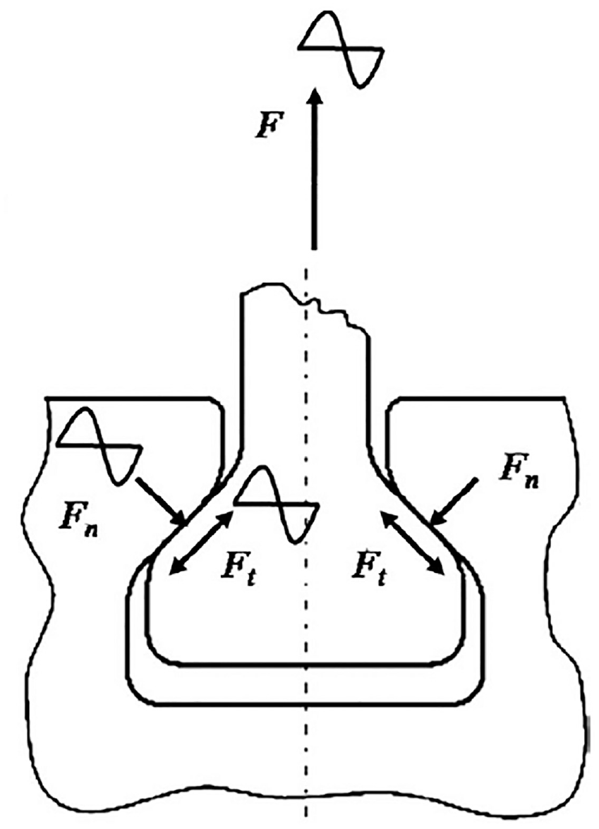
The blade/disk contact and loading condition of a turbine engine.
The frictional force creating the relative oscillatory motion can be less than that required to create gross sliding over the contact area as a whole. This results in a small central zone of no relative motion within the two contacting surfaces known as the stick zone. This type of contact is known as partial slip contact. The relative motion within the slip zone of the contact gives rise to wear that in turn brings about crack initiation at the border of slip and stick zones within the contact region. Vingsbo and Soderberg 22 produced a series of fretting fatigue maps to identify the three contact regimes (Stick, stick-slip, and gross slip) in terms of the two variables, normal load and displacement amplitude, or normal force and shear load as shown in Figure 2(a). From the experimental results reported in the literature, Vingsbo and Soderberg 22 estimated the transition displacement amplitudes between the three regimes. For instance, the transition between the partial slip regime and gross slip could occur at the displacement amplitudes between 3 and 25 µm. However, this range of amplitudes is not a rigid range for maximum fretting fatigue damage, that is, it generally depends on contact type, specimen geometry and material, loads. Using the maps of fretting fatigue makes it possible to identify the value of slip amplitude at which the minimum fretting life occurs.

As Figure 2(a) shows, that minimum fretting fatigue lives occur in the partial slip regime. In this regime, sharp peaks in shear stress occur at the stick-slip boundary as shown in Figure 2(b). In the regime a central stick region is surrounded by an outer slip region. Wear occurs in the slip region but little surface damage occurs in the center of the contact. Cracks initiate from the worn damage region due in part to micro changes in surface geometry and the stress concentration resulting from such changes. The most damaging contact regime in fretting fatigue is well known to be the partial slip regime where the fretting fatigue life decreases with increasing slip amplitude. 24 The reduction in life with increasing slip amplitude in partial slip regime can be explained by the shear traction distribution on the contact interface. The total shear force Q applied to the contact interface is given by the following equation 24 :
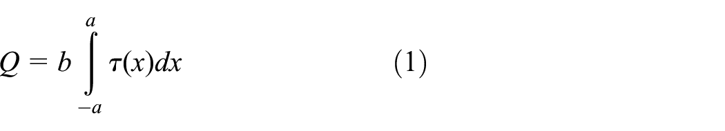
Where τ(x) is the shear traction at point x, b is the specimen width, and a is the contact semi-width. Until gross slip is prevailed, increasing in slip amplitude results in increasing frictional force, so the trailing edge of the contact stresses scales up, thus reducing the predicted fatigue life. If slip amplitude is increased so that the gross slip condition is exceeded (Q>μP), the frictional force cannot increase any more so that the trailing-edge stresses and predicted fatigue life are largely unaffected by further increases in slip amplitude. At this point, the predicted fatigue life has reached a minimum. 24
The increase in fretting fatigue life in the gross sliding regime can be explained by “crack wipe-out mechanism”. 25 According to this mechanism, in the gross slip regime the micro-cracks are eroded before they get the chance to propagate. Fretting map developed by Vingsbo and Soderberg 22 provides a clear picture of the relative damage of the three contact regimes. Nevertheless, this map is comparatively old and its accuracy is under question. 26 As an example, transition to reciprocating sliding wear for the low wear rate regime at low displacement amplitudes has been largely debunked by recent studies.26,27 At low amplitudes of displacement, a “stick regime” is found with no crack initiation which is somewhat disagrees with the Cattaneo-Mindlin-Ciavarella-Jaeger 28 classical map for which at the edges of the contact the slip should immediately initiate for arbitrary small tangential forces.
The eventual objective of fretting fatigue investigations is to predict unexpected in-service failures and safeguard the systems against them. To this end, significant efforts in the literature has been placed on fretting fatigue life estimation using experimental and numerical methods. Both fracture and damage mechanics have been utilized in the literature and the results usually are validated by experiment. The wear parameters the most well-known of which is the Ruiz parameter 29 have specifically been developed for fretting fatigue. On occasions, cumulative damage laws such as Miner 30 have also been used to predict the behavior of fretting fatigue under constant contact loading. There is still, however, no widely accepted technique for predicting fretting fatigue and current researches are still at the assessing stage of these tools. Nevertheless, the effect of variable contact loading has largely been ignored in the investigations. Most of the research works in this field has up to now been performed by Mall et al. 31 and Abbasi and Majzoobi.32–39 Contributions have also been made by Hojjati-Talemi et al. 23 , Xin et al., 40 Ciavarella et al. 41 and some others.42,43
The major objective of the present article is to review the most recent efforts in the literature handling fretting fatigue under variable contact loading. The effects of the main fretting variables, which are directly associated with the features of the testing apparatus, are described. The state of the art knowledge in contact mechanics regarding the variable contact loading is also briefly presented. Finally, the recent progresses in the field of fretting fatigue is outlined, and recommendations for future are suggested.
Testing apparatus
The early fretting fatigue researches were conducted using various test apparatuses. However, fretting fatigue testing has become increasingly standardized. Two types of loads are present within a fretting fatigue setup, global and local loads. Global loads include the normal and shear loads, which are applied to the pad, and the bulk axial load, which is applied to the sample as shown in Figure 3. The shear load is usually dependent on the amplitude of bulk axial load. The local loads such as shear stresses distributed over the contact interface are the main source to crack initiation.

Schematic of a typical fretting fatigue configuration.
The geometry of fretting contact has significant influence on the state of local stresses. It is highly desirable to know the stress distribution at the contact interface as this will facilitate the estimation of fretting fatigue life. This ends up in the utilization of idealized contact geometries during testing where, Hertzian, for example, spherical point or cylindrical line contacts are the most frequently used contact geometries. Analytical solution for the stress state within the contact zone is available for the commonly observed fretting loads. The rounded punch contact is also being increasingly employed in applications such as dovetail joints for which significant research efforts have been devoted in recent years. In 1960’s cylindrical fretting pads were increasingly used the stress distribution within the fretting contact zone were obtained by analytical solutions. The fretting global loads could be measured and controlled and hence fretting fatigue testing has moved increasingly toward standardisation. 44
In modern fretting fatigue testing, it is necessary to obtain as much control over the conditions in the contact region as possible. Finite element analysis (FEA) has been used to design a series of experiments having a specific stress distribution generated via the application of global loads. 45 The bulk axial load is usually supplied and controlled by a single actuator which is typically the main actuator of the hydraulic testing machine. The normal load is supplied by some sort of spring arrangements such as bevel washers, spring, bolt-nut connections or proving ring. The load is measured via strain gauges bonded to the proving ring or a load cell. We do not intend to present a detailed review of fretting fatigue apparatus and testing practices in this paper. However, the testing apparatus which have been designed and developed for fretting fatigue testing under variable loading condition are briefly addressed in this section.
A coupon scale test setup developed at U.S. Air Force Institute of Technology (AFIT) is illustrated in Figure 4. The test machine consisted of a rigid steel box frame, two 5 kN side horizontally opposed actuators and a 50 kN lower vertical servo-hydraulic actuator. All actuators were controlled using Instron 8800 function generator software. 46 The maximum contact load frequency created by this setup was about 40 Hz, due to the limitation of the hydraulic actuators, Nonetheless, in most of practical applications such as aero engines, which are subjected to fretting fatigue, the vibration frequency is much greater and may exceed even 200 Hz. 32

AFIT Multi-axis servo-hydraulic test machine setup for cyclic contact loading. 47
A full-scale biaxial rig illustrated in Figure 5 48 was developed at Oxford University. The test-rig can simulate the effects of blade vibration, disk expansion force, and centrifugal loading. Figure 5 shows a pair of blade specimens which have been tested using this apparatus. In actual dovetail attachment, the contact zone is rather flat with rounded corners; the variation of the forces induces bending moments and the contact area changes in a very complex manner. The initiation of fretting fatigue induced cracks at the edge of the contact may clearly be seen in Figure 5. The main limiting issue with this setup is that it is a full-scale test rig and therefore, the tests are expensive and time consuming and the results are complex to be interpreted.
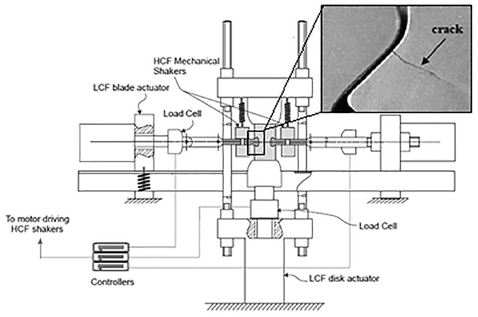
Schematic view of a biaxial fretting fatigue testing machine. 44
De Pauw et al. 49 designed and equipped a servo-hydraulic load frame with a fixture as depicted in Figure 6. A 100 kN hydraulic actuator is used to apply the axial fatigue load in the dog-bone specimen and the normal contact load is applied by a single servo-hydraulic actuator as shown in the figure. The tangential force, between the pads and specimen is generated by means of leaf springs. The tangential load, which is proportional to the fatigue load comes from the elastic deformation of the dog-bone specimen and compliance of the leaf springs. A lateral load cell is attached to the C-beam in order to measures the contact load directly. The induced tangential load is measured by a strain gauge attached to the compliance springs. The main limitation of this test rig is that it uses only one actuator to apply contact load. This may causes asymmetry of contact stresses at the two contact interfaces. Furthermore, the maximum contact load frequency obtainable by the device is 10 Hz, which varies in-phase with the bulk axial fatigue load.
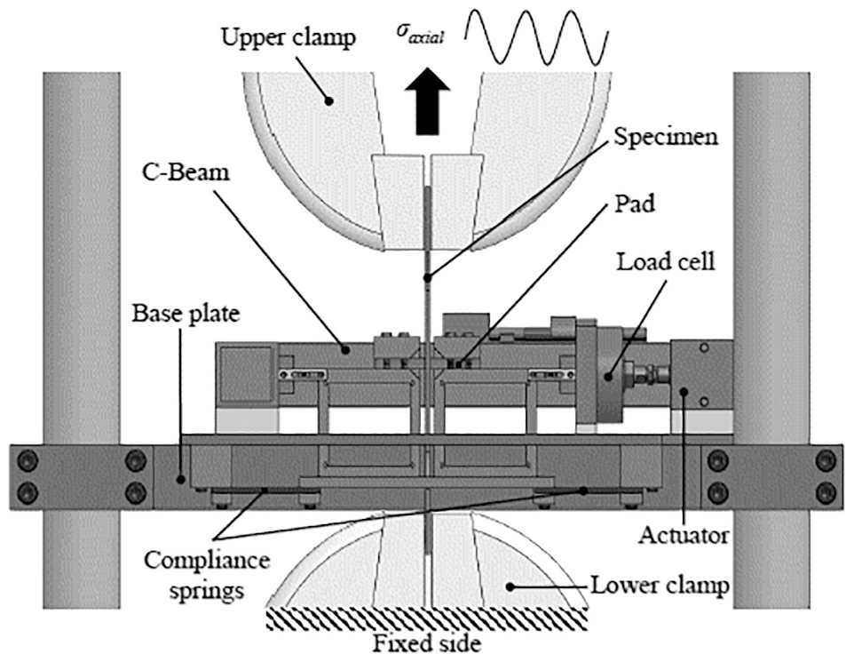
Schematic view of the fretting fatigue with adjustable compliant springs mounted on universal servo-hydraulic machine. 49
An electro-hydraulic servo tension-torsion fatigue test system was modified by Xin et al.
40
to simulate the oscillatory contact loading as shown in Figure 7. As the figure indicates, in addition to the bulk stress

A schematic view of the biaxial fretting fatigue testing machine. 40
More recently, a simple coupon scale testing apparatus shown in Figure 8(a) has been designed and developed by Abbasi et al. 32 to simulate the fretting behaviour of materials under cyclic contact loads. The main feature of the test rig is that a simple synchronized electro-mechanical system (a motor driven mechanism) is employed for generating the cyclic contact loads, rather than using hydraulic actuators which are complex, expensive and low frequency as shown in Figure 8(b). The capabilities to adjust the normal load independent of the axial loading and to change the phase between normal and far field axial loads are other useful features of the device. The device is additionally capable of generating cyclic loading with frequency of 0 to 200 Hz and amplitude of 0 to 10 kN. This range of frequency is the case for many engineering applications exposed to fretting fatigue such as dovetail joints in aero engines. A detailed description of the test-rig can be found in. 32
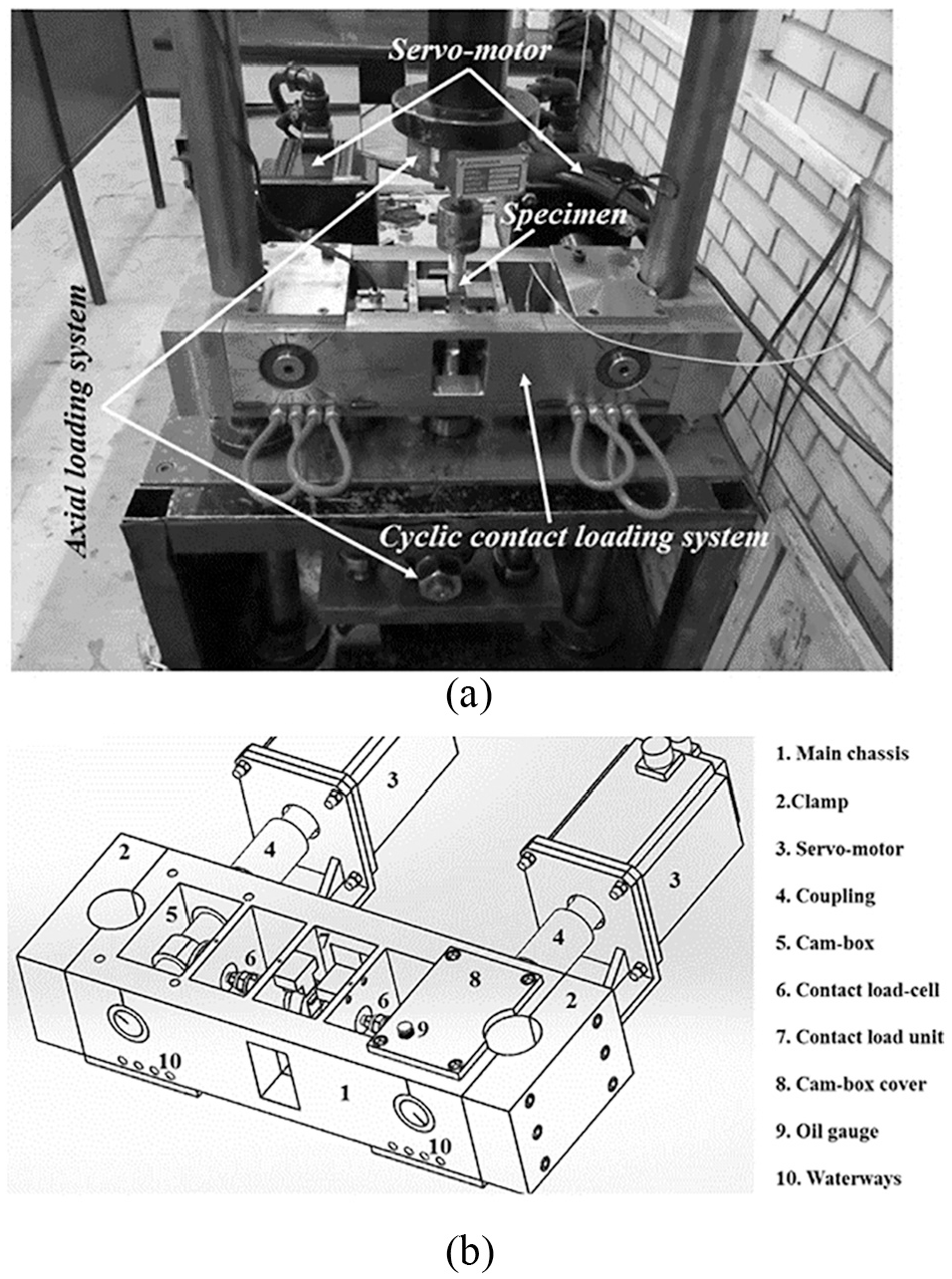
The test rig developed by Abbasi et al., 32 (a) general view and (b) schematic view of the device.
Summary of previous works
The analysis of fretting fatigue requires a thorough knowledge of multiaxial loading, contact mechanics, tribology, metallurgy, fatigue, and fracture, etc. These subjects involve a number of parameters such as bulk loads, local contact loads, contact geometry, frequency of applied loads, material behavior, slip amplitude, friction, and surface treatments that can affect fretting fatigue behavior of materials. These variables are not independent of each other. For example, the formation of fretting debris will affect the localized friction behavior of the contact. Despite this dependency, the variables can be divided into two groups, global and local variables. Other factors that may play a role in fretting fatigue crack initiation are persistent slip bands, fretting damage, localized heating effects at asperities and also the presence of debris.9,50
The application of contact loads both in a global and local context is what distincts fretting fatigue from plain fatigue. The application of the contact loads gives rise to localized stress concentrations at the edge of the contact surfaces between the pad and the specimen known as trailing edges. Although, the type, magnitude and distribution of the local stresses are influenced by the shape of the contacting components they are still severely dependent on the applied contact loads, that is, normal and shear force. Therefore, it is often difficult to characterize the effect of each variable individually on fretting fatigue life, as most of the fretting fatigue variables are interrelated. For such multi-variables investigations sophisticated test apparatus is required. In spite of this, attempts have been made to explore the relative importance of individual fretting fatigue variables on fretting fatigue life of component’s. 45 In the next sections, the major investigations on cyclic loading on the fretting fatigue behaviour of material reported in the literature are reviewed.
Katholieke Universiteit Leuven
The displacement field of an arbitrary vibration can be divided into three basic fretting modes characterized by a tangential, radial and rotational fretting as shown in Figure 9 for a ball-on-flat contact condition. Laboratory fretting experiments reported in literature up to now have focused on this mode I.22,51 Under fretting Mode II, the contact area oscillates between a banded limit under an oscillating normal load. This type of fretting takes place in practical applications such as surgical implants (e.g. dental restorations), aircraft components and automobile engine components.44,52,53 Finally, fretting mode III occurs under a twisting relative displacement so that slip occurs in a contact zone at the contact periphery whereas the inner zone remains locked. Huq et al.42,43 examined the effect of cyclic contact load on degradation mechanism in an alumina versus a WC-Co ball-on-flat contact under fretting mode II. Before the beginning of the test, a static normal load of 150 N was applied to the contact. During the tests, that normal load was subjected to a superimposed sinusoidal oscillation with a frequency of 35 Hz at a peak-to-peak amplitude of 200 N.

Schematic diagram of fretting modes.
The results indicated the existence of spalling and cracking in the slip area on the alumina sample. Analysis of the wear scar using EDS revealed the presence of oxygen in the slip area, whereas the presence of oxygen was not found in the central region. They concluded that oxidation in the slip region takes place as a result of the periodic exposure of the corresponding contact region to air. It was found that, the central locked region of the contact interface does not oxidize during fretting mode II since the central part of the wear track remains permanently in contact with the counter body.
Huq et al.42,43 conducted several tests for different numbers of fretting cycles at different normal loads and load amplitudes in order to determine the number of fretting cycles required to form a threshold crack or spalling dimension of 20 µm, which is of the order of several grain diameters. Their results led to a fretting map shown in Figure 10, where variation of maximum normal force versus the number of fretting cycles is plotted. The solid markers in Figure 10 indicate the tests carried out at a specific normal force where, for the corresponding number of fretting cycles, a threshold cracking of 20 µm was found on the surface of the alumina ball. This fretting map can be a useful tool for design purposes. For making a comparison between the constant and cyclic loadings, two fretting tests were conducted under the static normal loading of 160 N. The normal load was supplied by an alumina ball loaded on a WC-Co flat contact. The fretting tests were performed under Mode II for durations of 0.75e6 and 1.5e6 cycles. Cracking was not detected under static conditions either on the surface of the alumina balls or on the WC-Co plate. These results suggest that some precautions should be taken into account in designing components for contact conditions exposed to oscillating contact loads.

Fretting map for alumina balls under fretting Mode II. 43
Air Force Institute of Technology
In recent years, much attention has been paid to fretting fatigue of aerospace components in order to prevent catastrophic air disasters particularly heavy casualties in air crashes. The estimates by the U.S. Air Force indicate that one in six of all in-service high cycle fatigue related engine failures were due to fretting fatigue and galling. An estimated $ 20 Million spends annually on preventive measures by the US Air Fore. 44
At Air Force Institute of Technology (AFIT) many studies have been conducted on fretting fatigue behavior of material under cyclic contact loading condition. Iyer and Mall 54 studied the relation between contact load and frequency of the bulk axial load for Ti-6Al-4V. They reported that contact pressure reduces the fretting fatigue life for the axial load frequency of 1 Hz. However, no apparent effect contact load on fretting fatigue life was found for the cyclic axial load frequency of 200 Hz. In all tests, the trailing edge of the contact interface was found as that crack nucleation location. In another study by Lykins et al. 55 they observed that fretting fatigue life was independent of axial load frequencies of 1 Hz and 200 Hz. They concluded that, the major effect of axial load frequency on fretting fatigue is its effect on the level of oxidation that is allowed to occur in the contact region, as the oxidation process is time dependent. Heating effects at high frequencies may also be seen due to friction.
Jutte 47 examined the effect of cyclic contact loading on fretting fatigue behaviour of titanium alloy. It was reported that the cyclic normal contact loading has more damaging effect on fretting fatigue life than the constant normal contact loading. As Figure 11 shows, fretting fatigue life is lower for the tests with fluctuating contact loading than that for the tests with corresponding higher and lower constant contact loads. Figure 11 shows that fretting fatigue lifetime of specimens under variable contact loading is on average 70% lower than that for the corresponding lower constant contact loading and 33% lower than that for corresponding higher constant contact loading.

Fretting fatigue life for various contact loading conditions. 47
Lee 56 explored the effect of shot-peening on fretting fatigue response under both constant and cyclic contact loads for Ti-6Al-4V alloy. The experiments were done under four contact load frequencies of 0, 2.5, 10, and 30 Hz. The frequency of applied axial loads was 10 Hz. In all tests, fretting fatigue cracks were found to initiate near the trailing edge of the contact. Cracks initiated from the surface of un-peened specimens and from the interior points of shot-peened specimens. A modified shear stress range (MSSR) was examined to seek out their possible role in predicting fretting fatigue life. No correlation found between fretting fatigue mechanisms and contact load conditions, and shot-peening improved fretting fatigue life despite the contact load conditions. Lee 56 also showed that for both the constant and cyclic contact loadings, the MSSR parameter was effective in predicting the fretting fatigue life and crack nucleation location and its orientation.
The effect of phase difference between tangential and bulk axial loads on fretting fatigue response of Ti-6Al-4V was studied by Lee and Mall. 57 It was found that although both the tangential load and the relative slip varied with phase difference, however the effect of phase difference on the fretting fatigue life was negligible.
The effect of phase difference between contact and axial loads on fretting fatigue behavior of Ti-6Al-4V alloy was studied by Almajali. 58 The frequency was fixed at 10 Hz for both the contact and axial loads. The result reported by Almajali 58 showed that the fretting fatigue life for in-phase cyclic contact loading was the same as that for the constant contact loading. However, for the out-of-phase loading fretting fatigue life was increased, with respect to in-phase condition, from 20% to 30% in the low cycle regime and up to 150% in the high cycle regime. Al-Noaimi 59 studied the effect of phase angle between axial and normal contact loads on fretting fatigue behavior of Ti-6Al-4V alloy. He found that for the same applied axial load, fretting fatigue lifetime increased with phase angle. It was also reported that under variable contact loading conditions, the induced tangential load had the same frequency and remained in-phase with the applied axial load.
Ghent University
In fretting fatigue contact zones, the state of stress at and near the contact interface is extremely influenced by combination of axial, tangential and contact loads. The multiaxial nature of stress at contact interface can be severely influenced by phase difference between axial, tangential, and contact load. Using an uncoupled damage evolution model, Hojjati-Talemi et al. 23 studied the effect of various phase difference between axial and tangential loads on fretting fatigue behavior of aluminum 2024-T3 alloy. They also investigated the effect of variable contact loading on fretting fatigue response and crack initiation lifetime of aluminum 2024-T3 alloy. Figure 12 depicts a comparison between the predicted fretting fatigue crack initiation lifetimes for various phase differences and the experimental results. It is seen that by increasing the phase difference from 0 to 90 degrees the crack initiation lifetime improves. For PD = 180°, however, the crack initiation lifetime was predicted to be less than that for the 0 degree phase difference. Furthermore, as depicted in Figure 12, for variable contact loading, it was found that the initiation lifetime decreased almost at the same rate as it did for PD = 180°.

Fretting fatigue crack initiation lifetime for variable contact loading and different phase differences between axial and tangential loads (PD: Phase Difference). 23
Beijing Institute of Technology
A methodology was proposed to examine the fretting fatigue mechanism of AA6061-T6 aluminum alloy under cyclic loading condition by Xin et al. 40 From their study, it was found that the variable normal contact load will enlarge the slip area of the contact interfaces, making the crack initiation location contracts toward the center of the contact area. Variation of load amplitude, Pa, versus fatigue life, Nf, for different mean load, Pm, as reported by Xin et al. 40 is shown in Figure 13. As it is seen from the figure, for the same mean contact load level, fretting fatigue life declines as the contact load amplitude increases. Similar trend is observed for the mean contact load, that is, for the same contact load amplitude, fretting fatigue life diminishes as the mean contact load increases. From their study, Xin et al. 40 showed that the variable contact load will intensify the effect of the fretting on fatigue life, making the fretting fatigue life less than those in constant contact loading conditions.

Variation of load amplitude, Pa, versus fatigue life, Nf, for different mean load, Pm,. 40
Bu-Ali Sina University
Recently, Majzoobi and Abbasi32–39 attempted to identify the relative importance of several variables on fretting fatigue life of Aluminum alloy 7075-T6 under cyclic contact loading. The variables were contact load frequency, 33 phase difference between axial and contact loads, 34 peak pressure, 35 contact geometry, 36 shot-peening 37 and temperature. 38 The major findings by Majzoobi and Abbasi in their investigation on fretting fatigue response under cyclic contact loading are briefly addressed in the following sections.
Effect of contact load frequency
Fretting fatigue response of Al7075-T6 at different contact load frequencies was studied using an innovative test-rig shown in Figure 8. The results showed that fretting fatigue lifetime for the case of cyclic contact loading was less than the corresponding life under constant contact loading at the same axial and contact load levels as shown in Figure 14. As it is seen from the figure, fretting fatigue life sharply improves particularly for low stress levels, with increasing the contact load frequency. From Figure 8 it is also clearly seen that the fretting fatigue life at f = 80 Hz converges to its corresponding life at constant contact load condition. 33
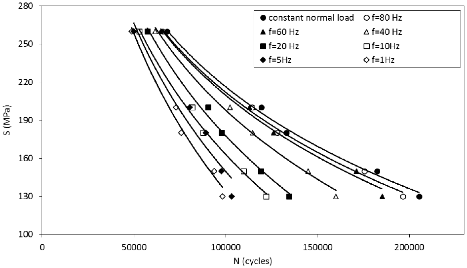
S-N curves for different contact load frequencies.
The contact load frequency is a determining parameter in fretting fatigue loading. The parameter significantly affects the size of the stick and slip regions, as does the magnitude of shear load. Optical microscopy observation of the fretting scar clearly showed that partial slip regime takes place at the contact interface as shown in Figure 15. As it is seen from the figure, under cyclic contact loading condition, the slip region size is larger and its extent is decreased with the increase in contact load frequency. In particular, the size of slip zone at the frequency of 1 Hz is about 1.67 mm (Figure 15(a)) which is substantially greater than the slip zone size at the frequency of 80Hz which is only 1.12 mm (Figure 15(c)). Larger slip region indicates that larger relative displacement occurs under cyclic contact loading condition especially for lower contact load frequencies. This is particularly the case for lower contact load frequencies as oxidation is a time dependent process. It is understood that the size of contact region undergoes oscillation due to the fluctuation of the normal contact load during the process of loading, making the extent of the contact zone to be unstable.

Optical microscopy images of slip area for different contact load frequencies: (a) f = 1 Hz, (b) f = 20 Hz, (c) f = 80 Hz, (d) constant contact load.
The major drawback of loading condition in Majzoobi and Abbasi 32 test apparatus is that the shear force are dependent on the stiffness of the bridge type fretting pad and also axial strain produced in the dog bone specimen. Thus, the level of shear force varies accordingly with oscillating the contact load in-phase with the axial load. Regardless of the stress time-history, under high contact load frequencies, the maximum friction force amplitude produced at the contact interface will be nearly the same as that for constant contact loading condition. On the contrary, if the contact load frequency is low, there will be no net friction force at the contact interface since the tangential friction force is released alternatively when the contact load decreases to its lowest level. This was confirmed by the results of numerical simulation shown in Figures 16 and 17 in which the slip region size declines and the shear stress generated at the contact interface increases with the increase in the contact load frequency. 33 This may also be a possible explanation for the smaller slip area at higher contact load frequencies in Figure 15.

Distribution of shear stress along the contact interface for different contact load frequencies.
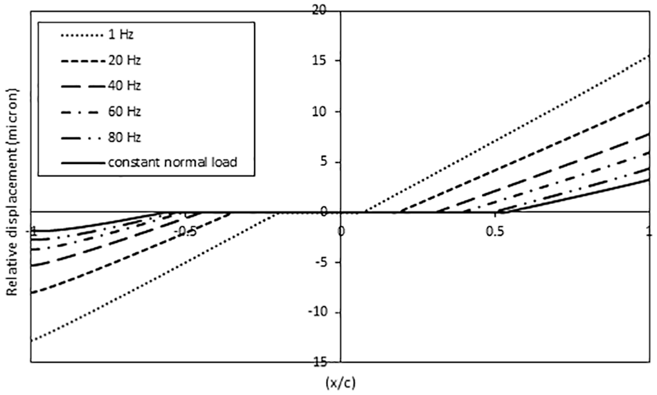
Distribution of relative displacement along the contact interface for different contact load frequencies.
Majzoobi and Abbasi 32 used the fretting map of Vingsbo and Soderberg, 22 shown in Figure 2, to explain the results of their fretting fatigue tests under cyclic contact loading. Vingsbo and Soderberg 22 demonstrated that small change in slip amplitude and subsequently wear can lead to a large change in life. The increase in slip amplitude experienced during the application of cyclic contact loading will lead to increase in wear and thus possibly to life reduction.
Effect of out of phase loading
Abbasi and Majzoobi 34 compared the results of the constant contact loading tests, with those of in phase, 90° and 180° degrees out-of-phase loads for the same frequency. The results are shown in Figure 18. It is seen from the figure that fretting fatigue lifetime has improved, with respect to the in phase loading, by 8% to 30% and 12% to 56%, depending on working stress, for phase differences of 90° and 180°, respectively. They concluded that the domination of gross slip regime at the contact interface along with the lower contact stresses are the main reasons for improvement of fretting fatigue life under out-of-phase loading condition.

Percentage of fretting fatigue life improvement versus working stress for various phase differences, with respect to in-phase loading.
The angle of crack growth is can provide useful information about one fretting fatigue mechanism. Fretting fatigue cracks initiate by shear stresses usually at an angle to the contact surface. Crack initiation is usually dominant by Mode II of fracture. The crack will then gradually changes direction until it grows sufficiently that the contact stresses no longer influence its growth. At this point, the crack will grow perpendicular to the direction of bulk axial load. Abbasi and Majzoobi 34 found that the initial crack angle relative to contact surface was 38-50 degrees for the constant contact load, 49 to 57 degrees for in-phase cyclic contact load and 65 to 70 degrees for out-of-phase conditions. A typical crack growth path can be seen in a specimen fractured by fretting fatigue and shown in Figure 19. As it is seen, the dog bone specimen is broken from the two opposite locations where the fretting pads touch the specimen surface.

Typical fretting fatigue crack trajectory in Abbasi and Majzoobi experiments.
Abbasi and Majzoobi 34 conducted a series of experiments to assess the effects of phase change between axial and contact loads on crack initiation and propagation lives. They employed a FE model based on Linear Fracture Mechanics (LEFM) to estimate the crack propagation lifetime. A symmetric quarter FE model of the fretting fatigue configuration including load and boundary conditions is shown in Figure 20. A detailed description of the FE simulation can be found in. 34
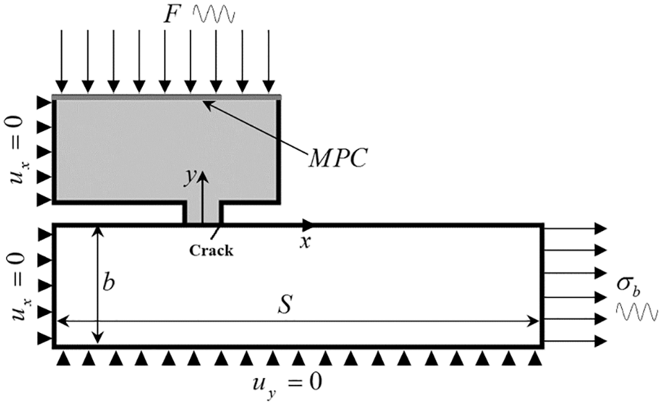
A symmetric quarter FE model of fretting fatigue configuration.
The results showed that while the phase difference had detrimental effect on crack propagation life, it was beneficial to crack initiation life. They found that depending on stress level, crack propagation lifetime was reduced by around 12% to 16% and 26% to 39%, for phase differences of
Effect of peak pressure
The effects of contact pressure on fretting fatigue behavior of Al7075-T6 under cyclic contact loading for contact load frequency of f = 10 Hz was studied by Abbasi and Majzoobi. 35 The results showed that, fretting fatigue life declined monotonically with the increase in contact load. 35 Figure 21 indicates the variation of predicted crack initiation and crack propagation lifetimes (Ni, Np) versus the applied axial stresses for different contact loads. In order to estimate the fretting fatigue crack initiation life, they subtracted the fretting fatigue crack propagation life predicted by the FE model, from the total fretting fatigue life obtained in the experiments. Figure 21 Show that with increase the contact and axial loads, the crack initiation portion decreases and as expected the crack propagation portion increases. They concluded that the reduction in crack initiation lifetime which is strongly controlled by the contact stresses is the main factor for decreasing the fretting fatigue life with increasing the contact load.

Variation of crack initiation and crack propagation lives versus contact load at different working stresses.
Effect of contact geometry
Fretting fatigue behavior of Al7075-T6 under cyclic contact loading for different contact geometries was studied by experiment and numerical simulation. 36 Two contact geometries including flat-on-flat (FP) and cylinder-on-flat (CP) were considered in the investigation. The frequency of contact load was set to be f = 10 Hz. Figure 22 illustrates variations of predicted crack initiation and crack propagation lives (Ni, Np) versus the working stresses, S, for both the flat-on-flat and cylinder-on-flat contact types with different pad widths. FPx and CPx demonstrates a pad width of xmm for flat and cylindrical contact type respectively.

Variation of S-Ni and S-Np curves for both the flat-on-flat (FP) and cylinder-on-flat (CP) contacts.
From Figure 22 it is seen that, for both of the flat and cylindrical contacts fretting fatigue life improves by increasing the pad width. 36 For cylinder-on-flat geometry, both of the crack initiation and crack propagation lives (Ni, Np) are significantly shorter than those for flat-on-flat geometries. However, the fretting fatigue life is dominated by the crack initiation phase for the cylindrical contact configuration. Majzoobi and Abbasi 36 concluded that the main reasons for reduction of fretting fatigue life in cylinder-on-flat configuration, can be attributed to (i) decrease in crack initiation lifetime due to increase in contact stresses that in turn is due to smaller contact width compared to flat-on-flat configuration and (ii) decrease in crack propagation life due to increase in SIFs.
Effect of shot peening
Shot-peening, is a common used cold-working treatment to enhance fatigue resistance of material in aerospace industries. The influence of shot-peening treatment on fretting fatigue behavior of material have broadly been studied under constant normal contact load over the past decades. However, less attention has been paid to its effects on fretting fatigue when the contact load is cyclic. A recent study by Majzoobi and Abbasi 37 showed that while variable normal contact loading declines the fretting fatigue life remarkably, shot-peening can improve it significantly in both high-cycle and low-cycle fatigue regimes. Depending on the axial stress level, the enhancement was about 89% to 207% and 26% to 143%, for the constant and cyclic contact loading, respectively. It was found that the residual stress induced by shot-peening led to an improvement factor of about 1.44 to 2.62 and 1.16 to 2.10 (depending on the axial stress level) in crack initiation and crack propagation lives, respectively. From their study two effects were found to be responsible to control fretting fatigue life of the shot-peened specimens under cyclic contact loading: compressive residual stress and surface roughening. It was demonstrated that, the beneficial effects of compressive residual stresses dominate over the detrimental effect of surface roughening, and hence resulting in fretting fatigue life enhancement.
Effect of temperature
Temperature is one of the most key factors affecting fretting fatigue behavior of material. The disk slot and blade attachment in the gas turbine engines are sensitive to fretting fatigue where the operating temperature can be as high as 260°C. 60 In order to improve the performance of aero-engines under this harmful condition, intensive efforts have been devoted during the past two decades.
Most of the investigations have shown that fretting fatigue lifetime under constant contact loading of the components subjected to high temperatures is much shorter.60,61 However, unless the results given by Abbasi and Majzoobi 38 no report on the effects of temperature on fretting fatigue behavior of material under cyclic contact loading can be found in the literature. Abbasi and Majzoobi 38 showed that the effect of elevated temperature on fretting fatigue behaviour in cyclic contact loading condition was more damaging than that in constant contact loading. The result showed that at higher axail loads where the fretting fatigue life is dominated by the crack propagation portion the detrimental influence of elevated temperature was more profound for crack initiation lifetime. In contrast, at lower axial loads where the life is dominated by the crack initiation portion the adverse influence of elevated temperature was more profound for crack propagation lifetime.
Contact mechanic in cyclic loading
The Hertzian contact geometry is the most popular fretting fatigue contact geometry. Hertzian contact refers to either a cylindrical line contact or a spherical point contact. Formulations of the Hertzian contacts have been accomplished by Hertz, 62 Mindlin 63 and Nowell and Hills. 24 Although Hertzian contact mechanics is useful, fretting fatigue occurs due to the combined normal and axial loadings. The application of axial loads does not greatly affect the distribution of normal stress within the contact region. The effect on shear stress is rather more significant. A point within the contact region will experience slip if the product of normal stress at the point and coefficient of friction is equal to the shear stress at that point, σ = µτ according to the Columb rule. It is therefore, possible for partial slip conditions to occur within a contact area as shown in Figure 23(a). The figure indicates that under the application of normal contact load and shear load alone the partial slip regime, the shear stress distribution consists of a central stick zone and one slip zone on each side of the stick area. The presence of a bulk axial load, S, has the effect of shifting the central stick region, e, towards the rear of the contact depending on the eccentricity level as shown in Figure 23(b). This implies that the center of the contact area can vary between x = e–c and x = e + c.

Schematic view of fretting fatigue contact: (a) The stress distribution on the contact area and (b) effect of bulk axial load, S. 24
Most of the partial slip approaches which have been reported in the literature use a method in which the shear stress distribution is assumed as the sum of shear stress due to sliding and a corrected term. Cattaneo
64
presented the first approach in which at the beginning a classical Hertzian contact is loaded by a contact load P along with application of a tangential load Q. The resulting tangential forces can be considered as the sum of the traction over a smaller central stick zone and a full slip tractions distributed over the entire contact area. Mindlin and Deresiewicz65–67 considered a range of cases where load is applied incrementally and showed that full stick regime would takes place if the increments ΔQ, ΔP in tangential and normal forces, respectively, satisfy the condition
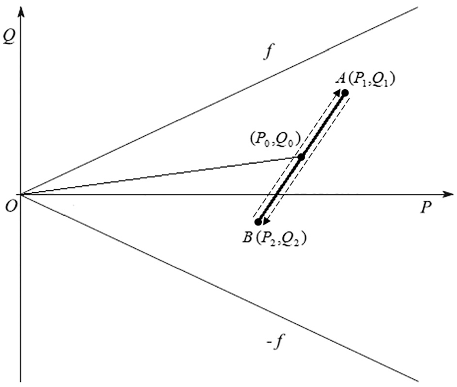
Barber et al. 68 have fully described the approach for computation of tangential load distribution during the steady state loading. This approach is briefly discussed in this section. Suppose that the normal contact and tangential tractions are defined by:


Where t is time and

PQ-space for cyclic loading. 68
The cycle consists of four segments BC, CH, HE, EB, where the points B, C, H, E are defined in Figure 25. As it is seen from the figure, the ellipse is traversed in the anticlockwise direction and dashed lines defining the points all have slope of


Periodic loading cycle including four segments of the ellipse in PQ-space. 69
If
Two dimensional load space for phase angle
Over the past recent years, several investigations71–74 have been focused on the “fatigue aspect” particularly to study the relation between fracture mechanics and the size of contact area. This relation was recognized by a model of fretting known as the “Crack Analogue” (CA) 71 which simplifies the shear traction distribution in contact problems. Recently Ciavarella et al. 41 proposed a modification of the CA model for cyclic contact fretting fatigue problems. This approach was first suggested by Giannakopoulos et al. 71 They suggested that the stress field created near the contact zone is similar to that created ahead of a sharp crack. Thus, using CA model it might be possible to predict the behavior of the contact problem by finding an equivalent crack. In the so-called CA model the fretting fatigue contact is approximated by an external crack under oscillating mode II. Since in Hertzian contacts the contact pressure goes to zero at the edges (non-singular shear traction distribution), the CA model is suitable if: (i) there is adhesive friction meaning that the coefficient of friction is high enough to create full-stick regime and (ii) the contact is sharp enough. Although the tribological features of the contact and localized surface damages are not considered in their model, the model is just a first effort which can be employed along with the multiaxial fatigue criteria’s for the fatigue design and final assessment in the presence of stress gradients. Furthermore, the theoretical formulation of the V-notched specimen should be extended to the fretting contact problems for making a comparison with the results provided by Ciavarella et al. 41
Conclusion and future directions
The literature review of the studies related to fretting fatigue under cyclic contact loading reveals that there has been substantial breakthrough in this area over the past decade. However, still many aspects of the subjects have remained to be solved. It is well known that complex cyclic contact loading have a detrimental effect of fretting fatigue behavior, reducing the fatigue life with respect to that for the constant contact loading conditions. The broad experimental investigations carried out by Abbasi and Majzoobi32–38 can assist to understand the fretting fatigue response of material under complex cyclic contact loading. However as stated by Ciavarella 75 it is very surprising that slip has occurred under proportional loading. He then concludes that contact mechanics looks unable to explain this basic point that its basics may not be applicable to the case where the frequencies of the contact and the other loads are different.
Recently studies of the contact mechanics under cyclic contact loading has made progress. Contact mechanic can predict the stress distribution within the contact region for idealized geometries and simplified loading. The situations where the loading is cyclic are more complex and often require the consideration of complex multiaxial loading, variable coefficient of friction, frequency effects and complex slip amplitude history. Generally, surfaces will assumed to be perfect and local asperity effects will be taken into account via the application of the coefficient of friction. This simplification leads to ignore the effects of debris build up due to the wear and oxidation especially in cyclic contact loading where the contact load is released periodically exposing the contact region to more oxidation. What the researches have done until now are only a building block and requires supplementary studies to be performed in future in order to eliminate the shortcomings of the existing tools and approaches, thus further investigation in both analytical and experimental are needed for fretting fatigue phenomenon with cyclic contact loading to be understood adequately.
As a suggestion for future works, by developing a test-rig equipped with suitable sophisticated measuring instruments, more documentary and realistic discussions can be provided by measuring the extent of oxide debris, exposure time to the oxygen, contact interface temperature rise, wear rate, slip amplitude and possible change in the coefficient of friction. In this study, the authors pointed out a need for new fatigue and contact mechanics models by revealing the aforementioned missing parameters. Damage parameters are still being assessed within the research community and it will be useful for a general consensus to be reached on what parameters most effectively model fretting fatigue and the conditions of their use. It is clear that any new parameter attempting to predict fretting fatigue under cyclic loading must use the ideology of damage accumulation over the contact region incorporating load interactions, wear and debris effects, frequency and changing the friction coefficient during cycling. Furthermore, Coulomb friction assumes that the value of friction coefficient remains constant where in reality it is likely to depend on local conditions such as asperities, sliding velocity, slip displacement, temperature, frequency and pressure. However, more complicated friction laws can led to complex non-linear dynamic effects. 76 The role of a different static and dynamic coefficient of friction also compels an energetic interpretation of friction. 77
Finally, in the context of fretting fatigue with cyclic contact loading there are still many latent aspects which must be clarified in future. Some of the way has been travelled but there is still a long way ahead to go.
Footnotes
Handling Editor: James Baldwin
Declaration of conflicting interests
The author(s) declared no potential conflicts of interest with respect to the research, authorship, and/or publication of this article.
Funding
The author(s) received no financial support for the research, authorship, and/or publication of this article.