
Abstract
Moment coupling in fretting fatigue experiments refers to the generation of moments when a shear force is applied, caused by the difficulty in designing fretting fatigue experiments where the shear is reacted out on the same plane as the contact. Digital Image Correlation is used to measure the effect of moment coupling, and a model is created to calculate the effect of the applied moment at any point during a loading cycle on near-edge contact properties. The effects of the changing contact pressure on the slip zone sizes are considered. Finally, the model derived is used to find a load cycle including the effect of normal contact force that creates a truly constant near-edge contact pressure distribution at one edge of the flat and rounded pad. Although the calibrations found in this paper are valid only for the specific rig and specimen geometry used in this paper, the method could be readily applied to other experiments.
Introduction
Fretting fatigue occurs in contact problems in the presence of partial slip, meaning that some region of the contact is permanently stuck and some region of the contact is undergoing cyclical reversing slip. The contacts conditions resulting from fretting fatigue processes result in a region where cracks can initiate, which can eventually result in component failure. Understanding the effect of fretting fatigue on component lifetime is therefore essential for assemblies in which crack propagation from contacts could result in dangerous failures of components, such as the contacts present at the root of fan blades in aero engines. 1
Experimental investigations in fretting fatigue are primarily based on matching the contact stress fields in a real problem with those in a much simpler geometry which is easier to analyse, such as a dog bone specimen in contact with a pair of profiled pads. 2 To match the stress field in the dog bone to that in the real geometry there are four loads that must be controlled; the differential bulk tension σ and shear load Q which affect the shear stress distribution along the contact interface, while the normal load P and moment M which affect the contact pressure distribution. 3
When contact problems are analyzed in half plane theory it is assumed that P and Q are applied through a point located at the centre of the pad and on the plane of the contact, so that their effects are uncoupled. In test machines it is difficult to react out the shear in the plane of the contact, so instead it is often supported at a fixed distance from the contact plane. In addition there is always a finite projection of the pad which behaves like a short cantilever in the presence of a tip shear force. This results in ‘moment coupling’, where the application of a shear load results in the simultaneous application of a moment. This presents a particular problem when ‘flat and rounded’ or ‘square’ pad geometries are used, as the application of a moment can result in significant changes in the normal contact pressure adjacent to the edge of contact, or, in extreme cases, the lifting off of one edge of the punch. 4
Experimental setup and measurements
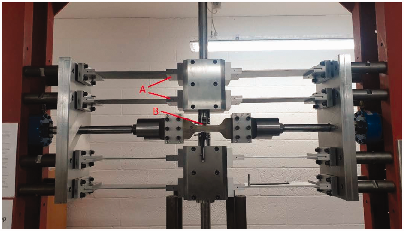
Experiments were conducted using the rig, Figure 1, located in the Servo-Hydraulic Laboratory at the University of Oxford. This test apparatus was originally designed to perform high temperature experiments to simulate the conditions present in gas turbine engines, which resulted in the support frame being extremely large to ensure there was sufficient thermal isolation between the specimen and the hydraulic components. This has resulted in significant problems with rigidity, and, in order to allow for the installation of a furnace, the shear force is reacted out through the plate springs (A) at a significant distance from the contact interface (B).
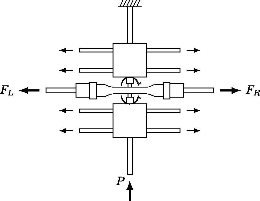
An overview of the rig showing the load paths present is given in Figure 2. The left and right actuators apply loads to each end of the dogbone specimen, while a third actuator at the bottom of the rig applies the pad normal load, P. The shear load applied to each pad is therefore given by
In tests a pair of flat and rounded pads with 15 mm central flat and 1.5 mm corner radius were used. These were pressed into a steel dogbone 30 mm high with a thickness of 6 mm. 5 The ends of the dogbone were serrated to provide a fatigue resistant connection to the actuators, and pin joints were subsequently fitted between the dogbone and the horizontal actuators to prevent twisting of the dogbone due to any slight misalignments (not present in Figure 1). This pad and dogbone geometry was used throughout all subsequent measurements.
It is not possible to measure the coupled moments or contact pressure directly, so instead the surface displacements of the pad and dogbone are measured, and the moment calculated from the resulting deflections. Digital image correlation (DIC) was used to measure these displacements; in this method a speckle pattern is applied to the surface of the components, a series of pictures of the component is taken during the load cycle and software is used to derive the motion and deflection of the components. Digital image correlation has previously been applied to fretting fatigue experiments, for the measurement of coefficient of friction, 6 slip 7 and strains, 8 for example.
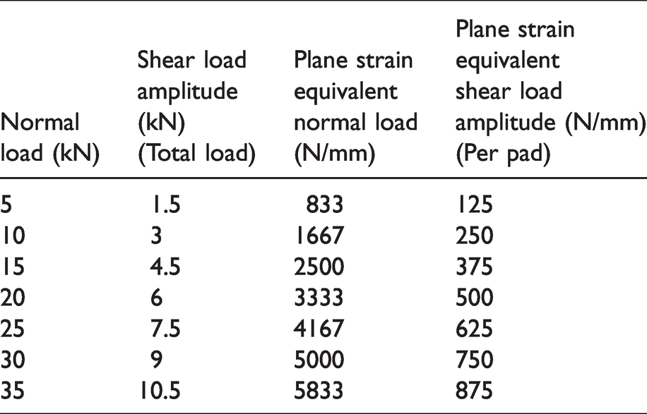
It was suspected that there would be a small amount of coupling between the application of the normal load and the moment, due to distortion of the frame. A series of digital image correlation measurements was therefore taken. The pads and dogbone were prepared with a speckle pattern using black and white matt spray paint. A Point Grey camera was used to capture greyscale images of the dogbone and pads at 2 frames per second at a resolution of 4240 × 2824 pixels. The digital image correlation software MatchID was used to check the quality of the speckle pattern and to process the collected images. The loads given in Table 1 were used, to cover fully those arising in typical fretting fatigue tests. To ensure that only partial slip was present a maximum shear force of 15% of the normal load was applied to each pad. The actuator at the left hand of the rig was set to maintain a fixed load of 15 kN, while the actuator at the right hand side of the rig was cycled to apply the shear load.
Loads used for measurement of moment coupling.
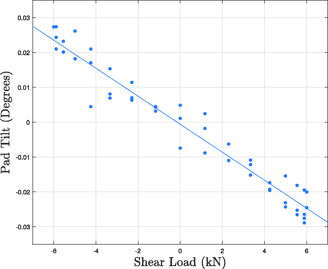
After the images were processed the DIC software was used to track the vertical displacements of two regions of points located adjacent to each edge of the pad. For each of these regions the vertical displacement of the edge of the pad was measured and the difference between the two measurements was used, in conjunction with the known width of the pad, to calculate the angle of pad tilt. By matching the image with the maximum amount of pad tilt to the peak of the load cycle it is possible to generate a plot of pad tilt vs applied shear load, an example of which is shown below in Figure 3, for the case of 20 kN applied normal load. It was found that for all 7 cases investigated the angle of pad tilt varied linearly with applied shear force.
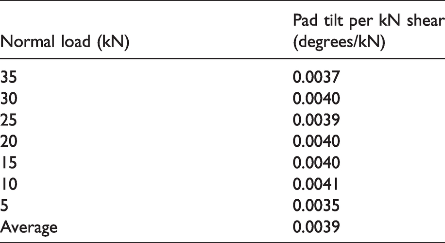
In order to ascertain how the angle of pad tilt per unit shear varied with applied normal load a linear model was fitted to the measurements for several values of normal load, and the gradient of the line found, given in Table 2. It was revealed that there was no systematic variation in the amount of pad tilt per unit shear load with changing normal load, the value being fixed at a mean value of 0.0039 degrees/kN.
The measured coupling between pad tilt and shear load at each of the applied normal loads.
Calculation of equivalent moment and creating a calibration
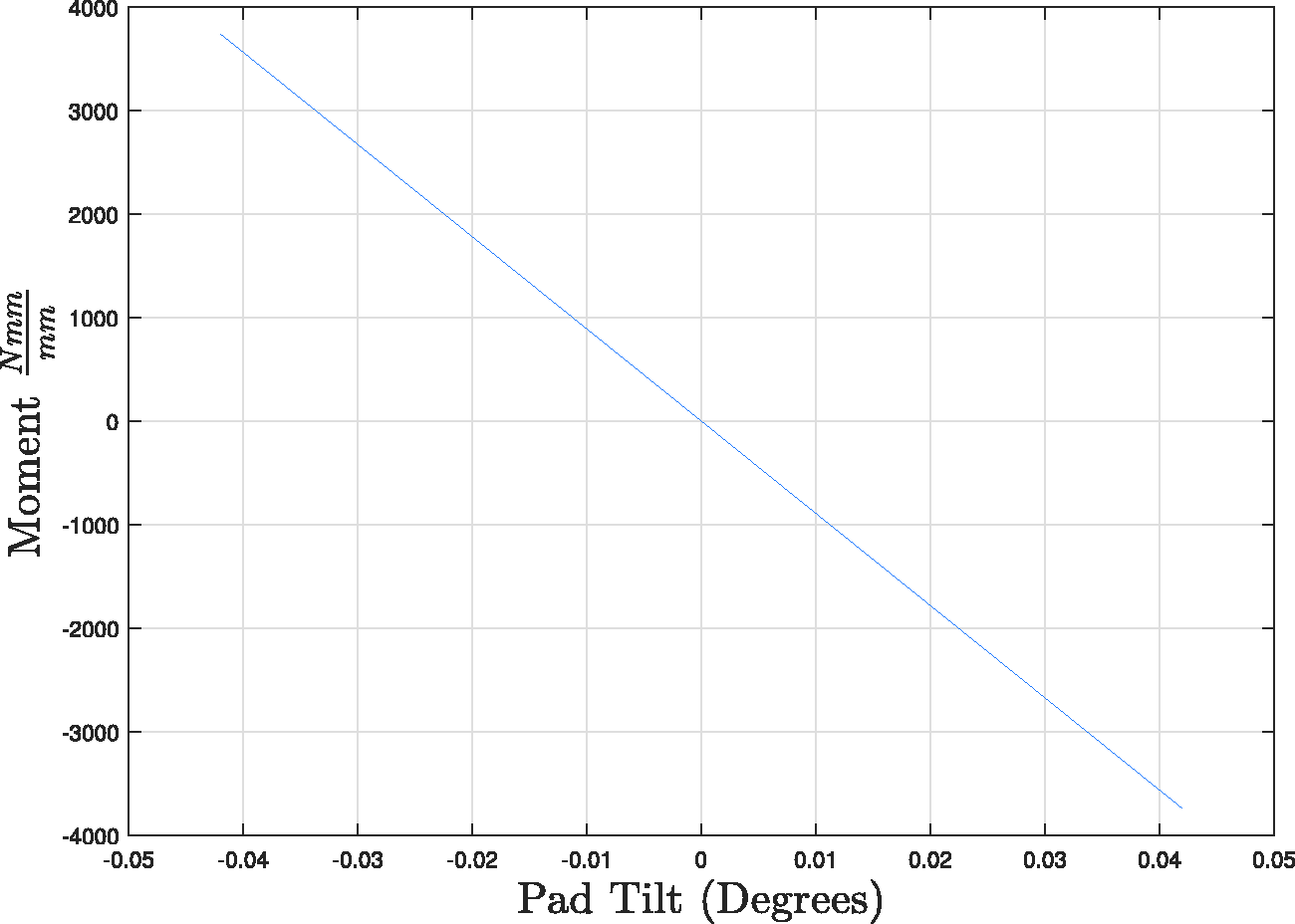
In order to convert the measured angle of pad tilt into an equivalent applied moment a closed form solution for a tilted flat and round contact subject to normal load and moment is used, derived in Andresen et al. 9 This was implemented in a MATLAB script, kindly provided by Dr H. Andresen. 10 The magnitude of the moment developed will depend on the normal load and the angle of pad tilt, so for each value of the applied normal load the equivalent moment was calculated at steps of 0.001 degrees over the full range of pad tilt experienced at each value of normal load. It was found that, over the range considered, the magnitude of the moment varied linearly with pad tilt for all 7 loading cases considered. An example plot for the case of a normal load of 35 kN is shown in Figure 4.
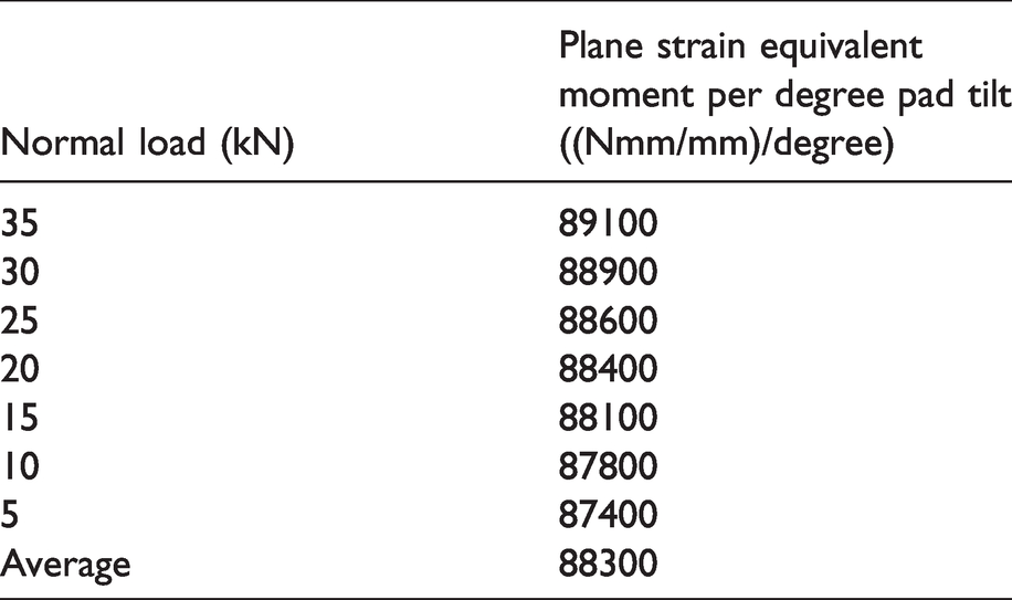
The final thing considered is the effect of the normal load on the magnitude of the moment coupling. For each value of normal load the moment per degree of pad tilt was noted, and the results are shown in Table 3. Although there is some variation of the moment with applied normal load, with higher normal loads implying a greater degree of coupling, this effect was extremely small, with the difference between the 5 kN case and the 35 kN case less than 2%. It was therefore decided to ignore this effect and assume that the relationship between moment and pad tilt was constant, with the value simply given by the mean of the calculated values.
The effect of varying the normal load on the magnitude of the moment coupling.
It is now possible to create a calibration that allows us to express the magnitude of the coupled moment developed as a function of the applied shear load. Starting with the data in Table 2 we can express the relationship between the angle of pad tilt and the plane strain equivalent shear as


In order to validate this expression the equivalent moment was calculated at the point of maximum shear force for each of the 7 load cases that were measured. This moment, in conjunction with the normal load are used as inputs to the tilted pad solution, 9 and it was found that the implied angle of pad tilt was the same as the maximum angle of pad tilt measured with DIC.
Effect of the coupled moment
Having found an expression that allows us to calculate the magnitude of moment developed in a fretting fatigue experiment we now wish to consider briefly what effect it will have on the contact, first by finding its effect on the contact pressure distribution, and finally on the size of the slip zones. In the following calculations we will consider only the behaviour of the pad for the 35 kN normal load case as a representative example.
The load on the dogbone will vary between two points as the shear is cycled. At the first point the left actuator (when viewed from the front, as in Figure 1) will be applying 15 kN of tension while the right is applying 4.5 kN, resulting in an overall shear force of 10.5 kN acting to the left and a bulk tension of 25 MPa. At the second load point the left actuator will be applying 15 kN tension while the right actuator applies 25.5 kN, resulting in an overall shear force of 10.5 kN acting to the right and a bulk tension of 83.3 MPa.
Effect on contact pressure
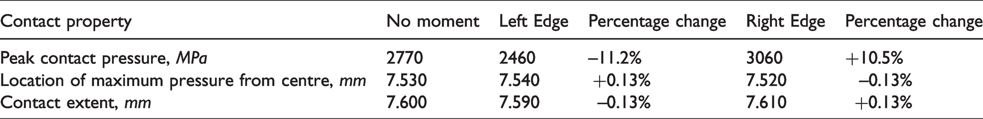
Figure 5 shows a direct comparison between the contact pressure for the flat and rounded pad both including and excluding the effect of the moment, at the point in the load cycle where the right actuator is applying a tension of 4.5 kN. The plots here show only the outermost regions of the contact,
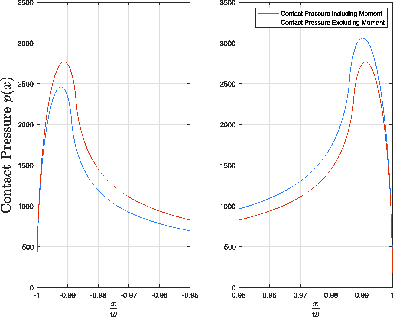
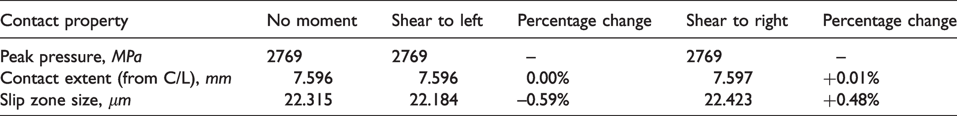
Some measures of the effect of the moment on the normal load distribution.
Effect on slip zone size
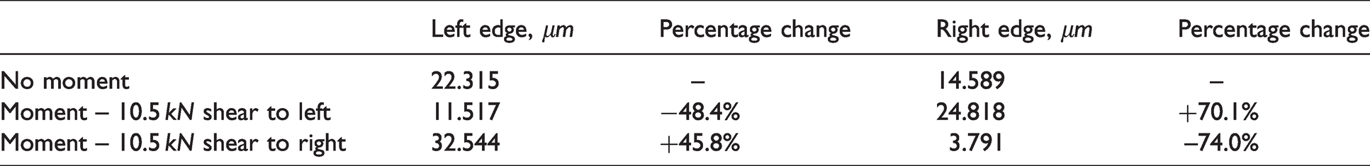
We will now briefly discuss what effect the application of the moment has on the size of the slip zones at each end of the contact, again for the 35 kN normal load case. The steady state slip zone size for a contact subject to varying moment, normal load, shear load and bulk tension can be found analytically, as analyzed in Andresen et al. 11 The slip zone sizes found in this way are shown in Table 5, given in microns, and assuming a coefficient of friction of 0.55. It can be seen that the change in slip zone size is rather significant in this setup, as the change in the half width of the contact is of the same order of magnitude of the slip zone size.
The effect of the coupled moment on the size of the slip zone at each edge of the contact.
Removing the effect of the moment
Calculating a load cycle
We now wish to create a loading cycle such that the effect of the moment is cancelled out at one edge of the contact. In the previous section we saw that when the shear load was acting to the left the left hand edge of the pad lifted off, and the contact pressure reduced. To counteract this we could therefore simultaneously increase the pad normal load when we apply the shear, such that the local contact pressure remains constant. We can treat the case when a shear load is applied to the right in a similar manner. The left hand edge of the pad ‘digs in’, and the contact pressure increases; we must therefore reduce the pad load to maintain a constant contact pressure.
It should be noted that it is only possible to cancel the effect of the moment coupling at one edge of the contact, and varying the normal load in this manner will increase the pressure variation at the other edge of the contact. In the majority of fretting fatigue experiments this is unlikely to be important because we are concerned with matching the near edge contact pressure only in the neighbourhood of crack nucleation. Most specimens are loaded with a combination of shear and bulk tension, the effects of which are additive at one edge of the specimen and subtractive at the other. For most tests we know at which edge of the contact failure will occur before starting the experiment.
In the following example we will match the contact pressure at the left hand edge of the contact by adjusting the peak contact pressure to that found in the no moment case. A MATLAB script is used with an iterative solver to find the appropriate change in normal load. Using this solver we arrive at the load cycle given in Table 6.
The load required to remove the effect of the moment at the left hand edge for the 35 kN normal load cycle, with shear loads as given in Table 1.
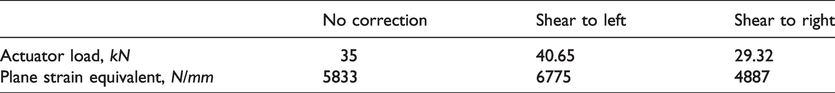
Figure 6 shows a three way comparison between the contact pressure for the idealised case where no moment is present, the contact pressure including the effect of the unwanted moment, and the contact pressure from the load cycle with the normal load correction. The top plots are for the case where the shear force is acting to the left, the bottom plots are for the shear acting to the right. As predicted it can be seen that by varying the normal load appropriately an extremely close match in the contact pressure at the left edge of the contact may be achieved, but at the expense of a larger deviation at the right hand edge.
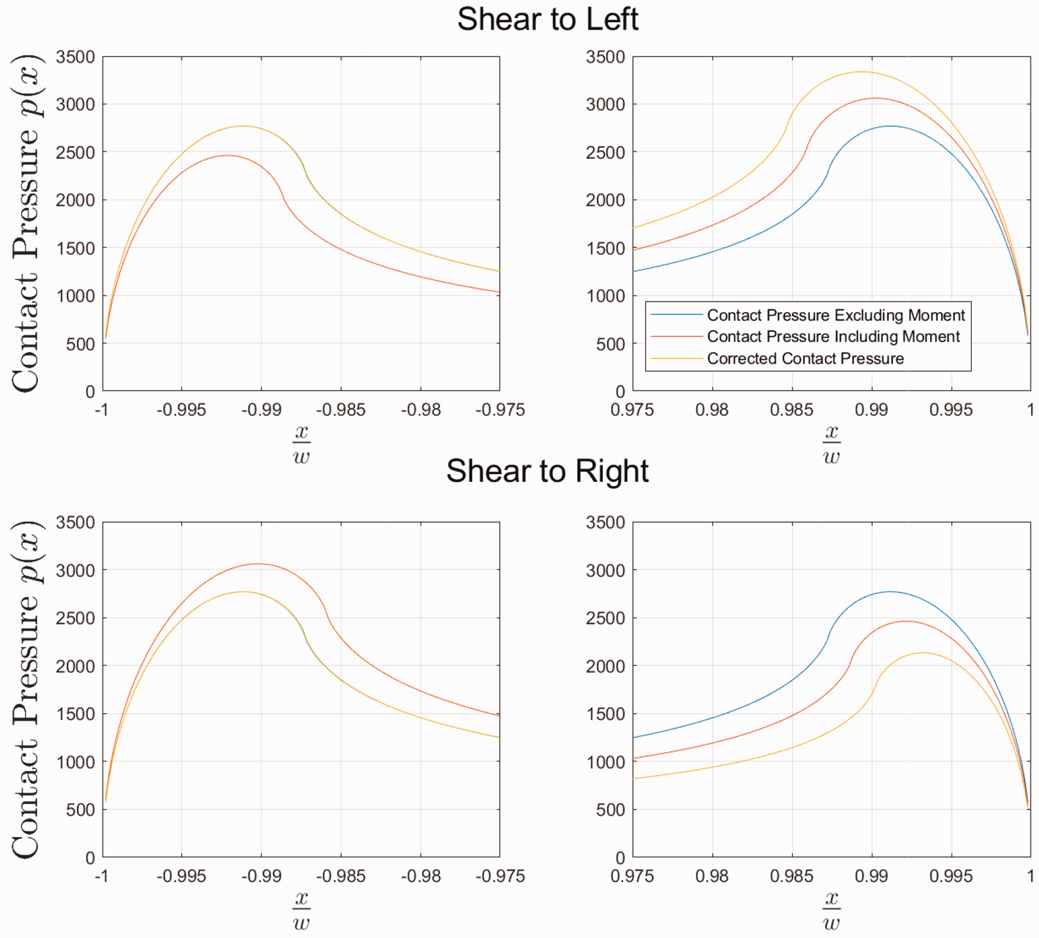
Table 7 contains a variety of contact properties, calculated for both the idealised no moment case and the moment corrected load cycle. It can be seen that in comparison to Tables 4 and 5 that the error is much smaller, in all cases being less than 1%, indicating a good match between the theoretical constant load cycle and the moment corrected cycle.
A table comparing a number of properties of the left hand edge of the contact for the idealised case with no moment coupling (only shear and normal loads), and the corrected load cycle with the shear acting both to the left and the right.
Experimental validation using DIC
The same DIC setup that was used to measure the magnitude of the moment coupling was used to check that varying the normal load created a constant contact pressure at one edge of the contact. The Test rig was set up with the same specimen and pad combination as used in the measurements, and were loaded with the derived varying normal load cycle. The vertical displacement of each corner of the pad was recorded over 2 load cycles.
Figure 7 shows a plot of the vertical displacement of each end of the pad for the 20 kN nominal normal load cycle. It can be seen that the varying normal load cycle has successfully removed the effect of the moment coupling at one end of the pad, with the vertical deflection being reduced to approximately zero.
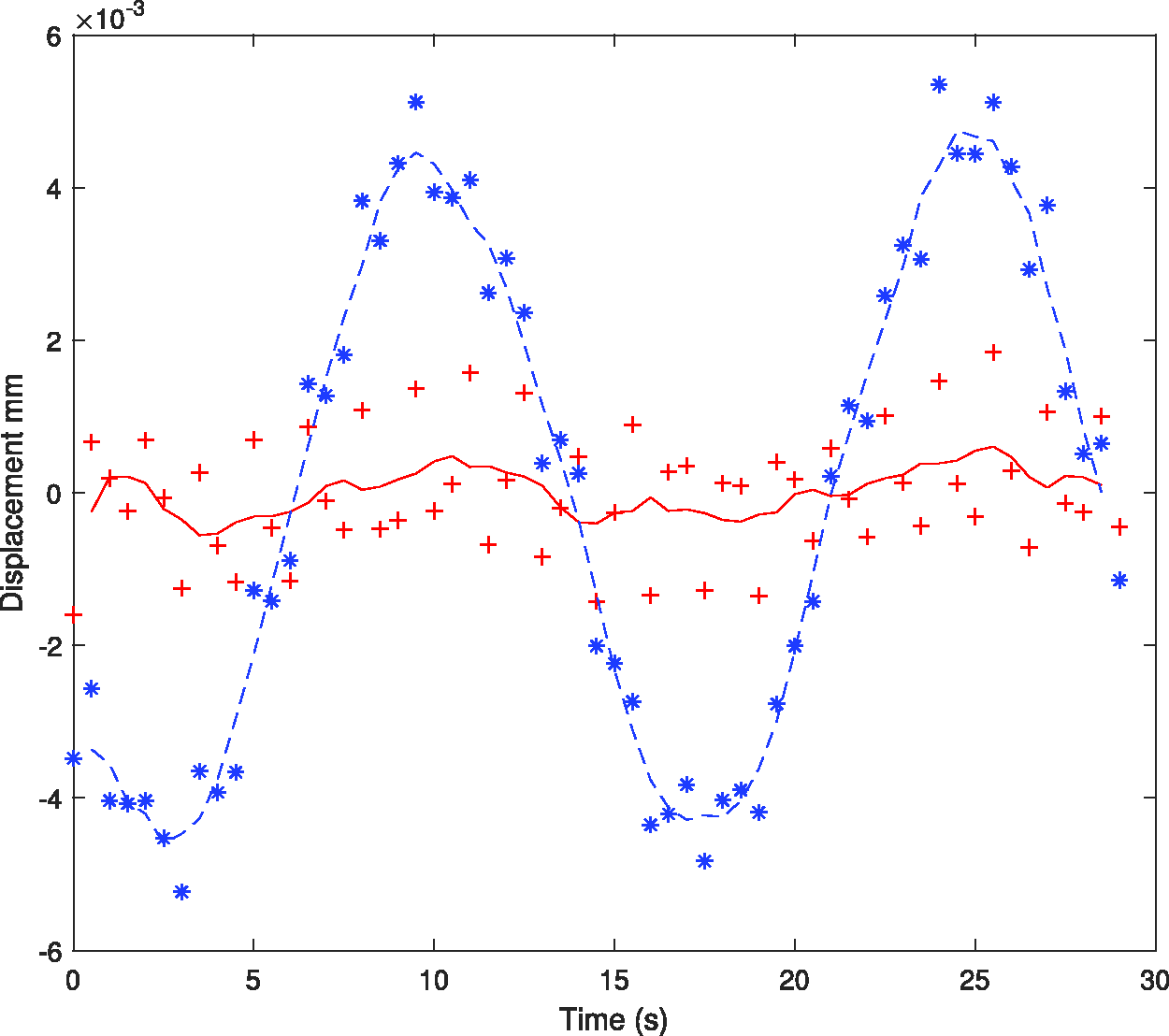
The vertical deflection of each end of the pad during two load cycles for the 20 kN nominal normal load case.
Conclusion
Moment coupling – the development of a rocking moment as a shear force on the contact is applied - is an unavoidable feature of fretting fatigue tests. It can be reduced by careful design but cannot be fully eliminated. When modelling the behaviour at the edge of contacts in fretting fatigue it is important that the action of moment coupling effects are accounted for. A method of measuring the magnitude of the moment coupling is derived through the use of DIC and a closed form solution for flat and rounded contacts, and a way of accounting for the coupled moment is found. The effect of the coupled moment is found to be non-trivial, particularly its effect on the predicted slip zone sizes. A load cycle with varying normal load is used to offset the effect of the moment, then DIC is used to validate that the resulting load cycle results in a truly constant normal pressure at one edge of the contact. Through this procedure it is therefore possible to match the behaviour of an experiment to an analytically derived load cycle in rigs with variable normal load actuation.
Supplemental Material
sj-pdf-1-pic-10.1177_09544062211043143 - Supplemental material for Measurement of moment coupling in fretting fatigue experiments
Supplemental material, sj-pdf-1-pic-10.1177_09544062211043143 for Measurement of moment coupling in fretting fatigue experiments by JPJ Truelove, DA Hills and L Blades in Proceedings of the Institution of Mechanical Engineers, Part C: Journal of Mechanical Engineering Science
Supplemental Material
sj-pdf-2-pic-10.1177_09544062211043143 - Supplemental material for Measurement of moment coupling in fretting fatigue experiments
Supplemental material, sj-pdf-2-pic-10.1177_09544062211043143 for Measurement of moment coupling in fretting fatigue experiments by JPJ Truelove, DA Hills and L Blades in Proceedings of the Institution of Mechanical Engineers, Part C: Journal of Mechanical Engineering Science
Supplemental Material
sj-pdf-3-pic-10.1177_09544062211043143 - Supplemental material for Measurement of moment coupling in fretting fatigue experiments
Supplemental material, sj-pdf-3-pic-10.1177_09544062211043143 for Measurement of moment coupling in fretting fatigue experiments by JPJ Truelove, DA Hills and L Blades in Proceedings of the Institution of Mechanical Engineers, Part C: Journal of Mechanical Engineering Science
Supplemental Material
sj-pdf-4-pic-10.1177_09544062211043143 - Supplemental material for Measurement of moment coupling in fretting fatigue experiments
Supplemental material, sj-pdf-4-pic-10.1177_09544062211043143 for Measurement of moment coupling in fretting fatigue experiments by JPJ Truelove, DA Hills and L Blades in Proceedings of the Institution of Mechanical Engineers, Part C: Journal of Mechanical Engineering Science
Supplemental Material
sj-zip-5-pic-10.1177_09544062211043143 - Supplemental material for Measurement of moment coupling in fretting fatigue experiments
Supplemental material, sj-zip-5-pic-10.1177_09544062211043143 for Measurement of moment coupling in fretting fatigue experiments by JPJ Truelove, DA Hills and L Blades in Proceedings of the Institution of Mechanical Engineers, Part C: Journal of Mechanical Engineering Science
Supplemental Material
sj-pdf-6-pic-10.1177_09544062211043143 - Supplemental material for Measurement of moment coupling in fretting fatigue experiments
Supplemental material, sj-pdf-6-pic-10.1177_09544062211043143 for Measurement of moment coupling in fretting fatigue experiments by JPJ Truelove, DA Hills and L Blades in Proceedings of the Institution of Mechanical Engineers, Part C: Journal of Mechanical Engineering Science
Supplemental Material
sj-pdf-7-pic-10.1177_09544062211043143 - Supplemental material for Measurement of moment coupling in fretting fatigue experiments
Supplemental material, sj-pdf-7-pic-10.1177_09544062211043143 for Measurement of moment coupling in fretting fatigue experiments by JPJ Truelove, DA Hills and L Blades in Proceedings of the Institution of Mechanical Engineers, Part C: Journal of Mechanical Engineering Science
Footnotes
Declaration of Conflicting Interests
The author(s) declared no potential conflicts of interest with respect to the research, authorship, and/or publication of this article.
Funding
The author(s) disclosed receipt of the following financial support for the research, authorship, and/or publication of this article: James Truelove expresses with thanks the award of an iCASE award ref 17000027 from Rolls-Royce plc which has enabled him to carry out this work.
References
Supplementary Material
Please find the following supplemental material available below.
For Open Access articles published under a Creative Commons License, all supplemental material carries the same license as the article it is associated with.
For non-Open Access articles published, all supplemental material carries a non-exclusive license, and permission requests for re-use of supplemental material or any part of supplemental material shall be sent directly to the copyright owner as specified in the copyright notice associated with the article.